-
Progress - Sortof
11/02/2014 at 21:31 • 0 commentsSo I've been approaching this project from a bit of a tangent, with the engineering sector strikes in South Africa I couldn't get any laser cutting done and it brought my prototyping to a standstill. As a result I decided to pursue a smaller project that I've been wanting to do for a while now which is a small CNC plasma cutter. It has a small 1,2m x 1,2m bed and is powered by an Arduino sporting a modified version of Grbl. It's all just about done and if I get time I'll start another project and do a write-up on it. I'm hoping it will significantly improve my ability to prototype parts for all of my projects.
All in all I hope to get back to my arm and have some interesting progress to show soon.
-
Distractions
09/09/2014 at 16:38 • 2 commentsSo I've made loads of progress with the design. I have changed the joints substantially and redesigned the base completely, this is after 3d printing most of the version 1 parts and seeing how everything looked together. After that I got very distracted working to improve my 3d printer and then with wedding plans. Everything has now settled down and I hope to be printing the V2 prototype parts over the next few weeks.
-
Photos
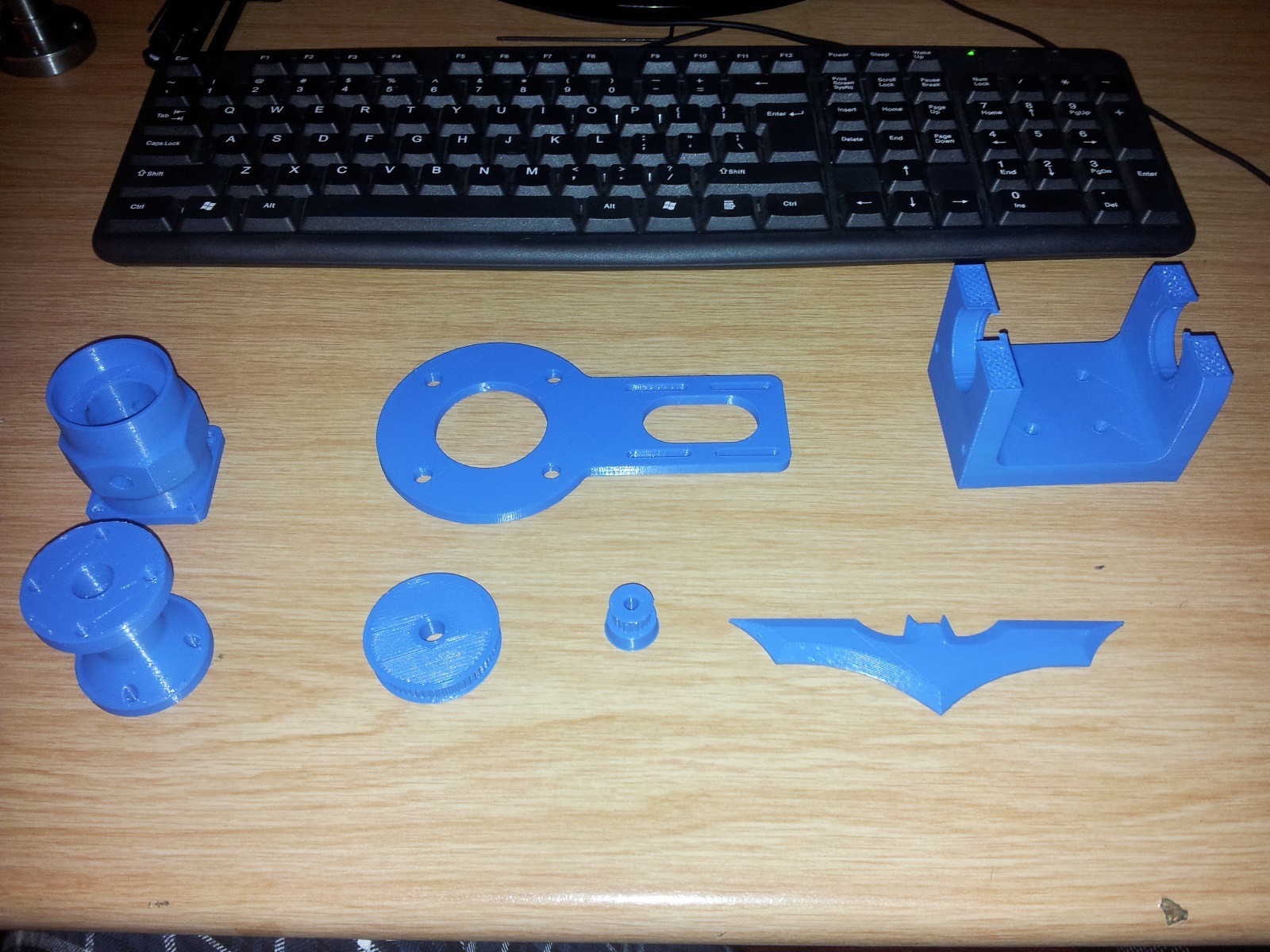
08/21/2014 at 21:31 • 0 commentsSo here is the photo of the 3d printed parts I promised. Been messing around with different concepts and trying to make all of the parts fit on my printer. The batarang was just a test print, plus I wanted one.
![]()
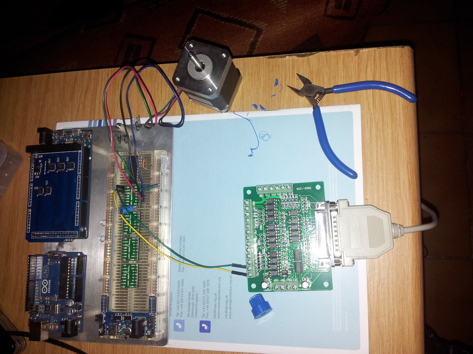
I've also been setting up to test the stepper motor drivers and controllers. In the photo is a simple paralell port breakout card with optocouplers and 4 of the Pololu 1.5A stepper drivers (along with an Arduino uno and a due I'm not using right now). I have about $600 worth of robot parts laying around and I'm getting anxious to turn it into something useful or at the very least entertaining.
![]()
-
3D Printing Success
08/19/2014 at 13:12 • 0 commentsSo I have managed to 3D print a whole bunch of parts for the arm. Not sure why I didn't do it earlier. I'll post up some photos tonight when I get home. With the 3D printing working the only thing stopping me from having a 3 degree of freedom arm working is time.
-
3d Printing
08/08/2014 at 09:11 • 0 commentsI went to a very interesting 3d printing workshop last night and I have decided I will be 3d printing my parts to double check fit and functionality before I manufacture them from steel or ali. Provided I can get my Reprap Ormerod working correctly I should have a moving axis or two by sunday. I will post the g-code files once I know each part will work so that anyone interested can print their own copy. The CAD files I will only release once the arm is at a working stage.
-
Strikes
08/06/2014 at 21:32 • 0 commentsSo the violent strikes here in South Africa finished last week and I can finally get to ordering parts without fearing for my life. If you think I'm exaggerating just Google it. I have managed to make some progress on the software side but I had to save up for some new pc bits so that I could retire my old pc and dedicate it to this project. So I am hoping to post some tangible progress this weekend. Hold thumbs.
-
Fun with Software
07/14/2014 at 19:23 • 0 commentsSo with the wage strikes here in South Africa keeping most of the engineering companies closed I'm continuing on with the software to control the arm. I am using LinuxCNC due to the open source basis, power and customisable nature of the software. You can follow my adventures in setting it up for a 6 axis arm here: http://linuxcnc.org/hardy/hardy/emc2/emc2/index.php/english/forum/10-advanced-configuration/28042-more-6-axis-kinematics-yay
-
Update
07/07/2014 at 11:05 • 0 commentsSo between my bike accident and violent wage strikes in the engineering sector here in South Africa I've managed to make only slight progress. I have figured out all of the forward and inverse kinematics and written a bit of python code check my calculations. It needs to be converted into a kinematics file for Linux CNC but that is fairly straightforward.
With the inverse kinematics the angle of each joint can be calculated from the given x, y, z coordinates and the tool orientation. I have decided to allow the orientation to be specified by the user in any one of 3 different ways.
1) Axis - Angle: this is a vector pointing in the direction of the tool head and an angle of rotation around that axis. This is the easiest to use if the end effector is some type of rotary tool like a drill or router. This is because the angle becomes inconsequential and only the axis contributes to the position of the arm.
2) Rotation matrix: This is a 3 x 3 matrix defining the transformation from the base coordinate frame to the tool coordinate frame. This is a bit clumsy for the end user however I'm converting all input forms to this in order to complete all of the kinematic maths so I've made it a valid input in case the user wants to use it.
3) Euler Angles: This is the pitch roll and yaw of the tool relative to the base coordinate frame. I suspect this will be used the most when a claw manipulator is used.
-
Delays
06/20/2014 at 08:27 • 0 commentsI was involved in a bike accident earlier this week so unfortunately all progress on the arm has come to a stop. I will hopefully get back to it sometime this weekend.
-
Parts Finally Start Arriving
06/17/2014 at 11:03 • 0 commentsSo a couple of parts have started to arrive, nothing that I can assemble yet but it's exciting none the less. I will lay out everything I have so far tonight and take some photos. I will only be able to start assembling end of next week, that's when the base mount should be done. I also have to design and make a tool for cutting custom GT 2 pulleys because I found that I can't source exactly what I want and I'm not prepared to compromise the design. It's quite a small tool because the tooth radius of the pulleys is just 1 mm so I'm probably going to have to wire cut it.
HIGH PERFORMANCE ROBOTIC ARM
An affordable 4/5/6 axis robotic arm design that can be easily made by students/enthusiasts developing for real world interaction.
 Andrew Becker
