Krunal
-
Developing Pressure Sender Hardware
08/20/2016 at 13:58 • 0 commentsTill now I have all the Pressure regulating hardware and software ready. All the tests are performed successfully. GUIs are used to monitor as well to control the motors.
The Hardware also is tested with the actual VFDs and motors. Till now, the steam pressure to the accumulator was simulated using another GUI. So now I have started to work on pressure sender hardware.
The main purpose of Pressure sender hardware is to read the pressure of the steam to the accumulator and send this to the VFD controller PCBs in the field over ethernet layer using UDP protocol. The actual distance between steam accumulator and the parabolic dishes is more than 100 meter, so direct connection of pressure sensor to the VFD controllers was not possible.
Apart from sensing pressure, steam temperature also needs to be monitored so the the heat energy in the receivers can be predicted. So a K-type thermocouple is also going to be used.
The pressure sensor is going to be standard with output range of 0V - 10V DC. This value is then stepped down to 0 - 5V DC using resistor network so as to make it compatible with arduino voltage levels.
For temperature sensing K-type thermocouple is to be used. AD8495 from Analog devices is used to amplify very small signals of thermocouple to higher range. AD8495 provides the resolution of 5mV/°C.
I am going to use the same hardware of VFD controller with slight modifications. RS485 interface is not required, so that part will be removed and resistor divider for pressure sensor and AD8495 IC for thermocouple will be added.
-
Developing GUIs
08/15/2016 at 12:02 • 0 commentsThree GUIs have been developed to test the code: The GUIs can be found here...
Two GUIs have been developed just to simulate Pressure sender and VFD to test the development...
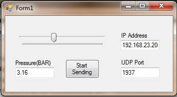
- Pressure Sender Simulator: This pressure sender PCB's work is in progress, so GUI simulation is used. It is acting as Pressure sender installed near accumulator. This GUI only send pressure to the Arduino VFD Controller. Pressure can be varied with track bar from 0 - 8 BAR in the step of 0.01 BAR. This GUI works on UDP protocol.
![]()
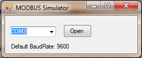
2. MODBUS Simulator: It is acting like VFD. Only Write one register of MODBUS fuction can be tested with this GUI. This GUI works on MODBUS protocol. This should be connected to the serial port of the Arduino VFD Controller while any other program using serial port of the Arduino should be closed before... (This is just test GUI and so I could not add all the MODBUS functions, however, all the codes are tested with actual VFD.)
![]()
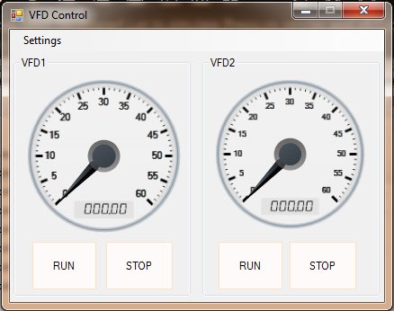
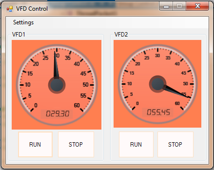
3. VFD Controller GUI shows the real time frequency of the both the motors, Also it shows the connection status of the VFDs. If any VFD is disconnected, it will show that in Red color else will be showing green in normal operation. User can even control each motor and can run/stop individual motor. We need to specify the IP address of the Arduino VFD controller to this GUI using settings tab(Default IP: 192.168.23.200). This GUI is not a functional requirement for the Arduino VFD Controller, but it is just for monitoring purpose.
![]()
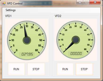
When both VFDs are connected and RS485 communication proper, then GUI will be green showing the actual running frequency of the VFD.
![]()
When there is any problem or if the communication fails, the GUI turn RED indicating loss of communication or some problem.
![]()
-
Making the actual hardware...
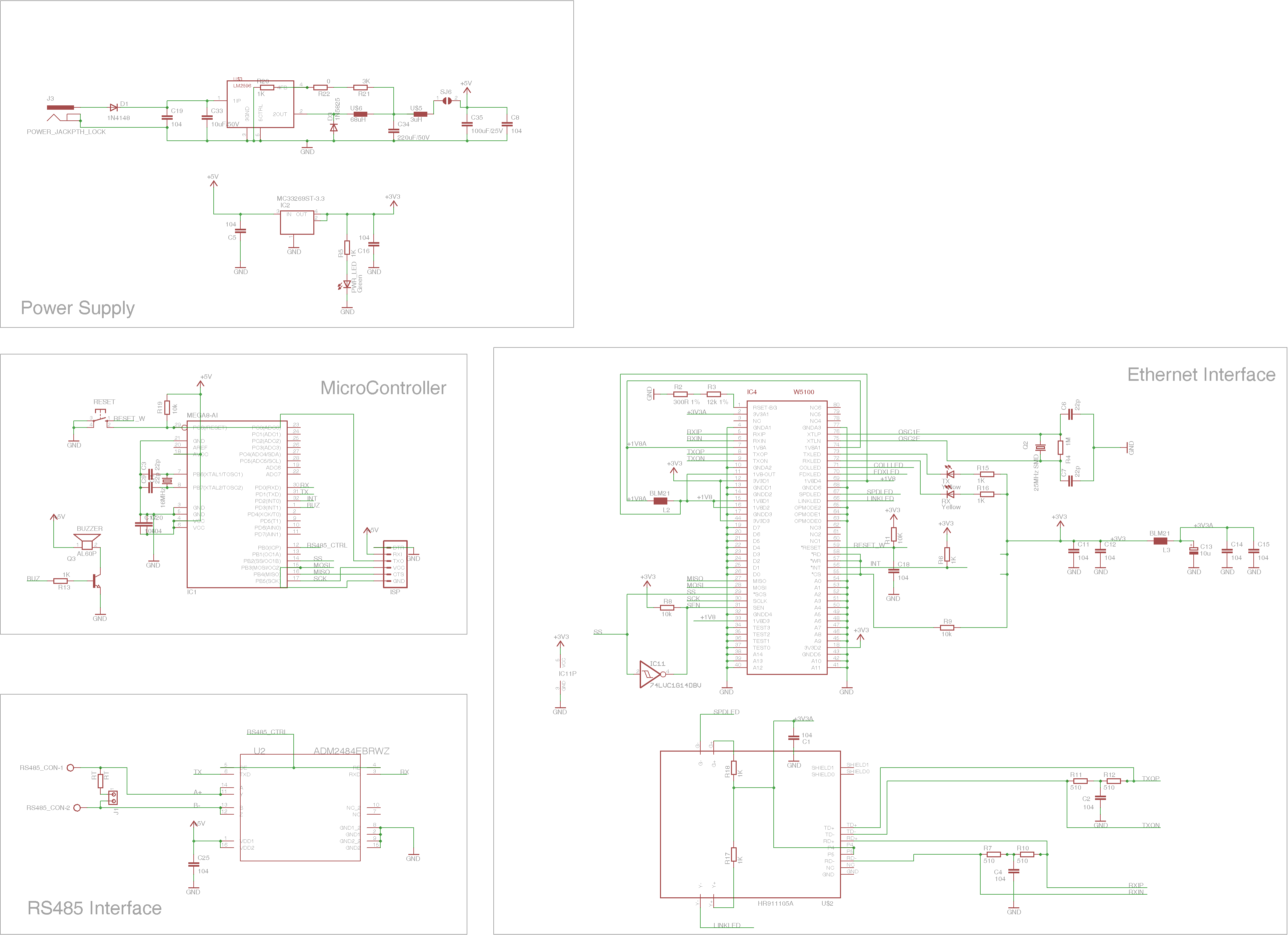
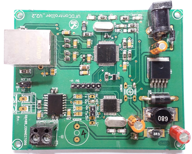
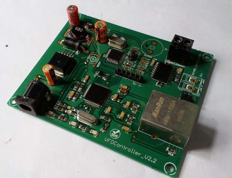
08/15/2016 at 10:30 • 0 commentsAfter testing the code on these hardware prototypes, I designed my customized hardware. The schematic is provided below.
To be mentioned:
1. I used switching regulator LM2596 as linear regulator was getting heated up a lot.
2. The interrupt pin of W5100 is connected to interrupt pin of Arduino.
3. Added buzzer for when there is any problem, buzzer will be made ON.
4. Used ADM2484 as RS485 transreceiver IC.
The schematic file can be downloaded from "Files" section.
![]()
![]()
![]()
-
Initial Tests with Arduino and ethernet shield
08/15/2016 at 05:59 • 0 commentsFirst of all I worked on hardware. I used Arduino Duimilanove and ethernet shield. I developed the code on this hardware prototype.
ADM2484 IC was used as RS485 transreceiver IC.
Arduino needs to do many works like:
1.Getting pressure reading from anther arduino system through ethernet
2. Process the data and calculating output frequency for each VFD by implementing PID.
3. Driving the VFDs with this new frequency using MODBUS over RS485.
4. Meanwhile if GUI asks for informatin then it has to send data packets to the GUI over ethernet.
To perform these many functions, the code needs to be free from polling the resources. So I decided to keep all the communications interrupt based.
The ethernet libraries for arduino are polling based and we need to check fr the received data regularly. To make use of interrupt capability of ethernet shield, you need to short INT jumper of ethernet shield.
1. I implemented MODBUS protocol on my own. Please note, for this I did not use inbuilt serial library as I wanted to control the serial receiver interrupt on my own. With USART RX ISR, I can monitor each byte and can process the data more faster as compared to polling method that would have required for inbuilt serial library.
2. While implementing UDP protocol, I needed to poll the UDP RX buffer to check the received data and thus it was taking a lot to respond to the information requested by the GUI. So I implemented interrupt based ethernet communication. Interrupts for all sockets has been enabled.
Finally I had the working prototype ready. Next step was to get everything on the same PCB.
Pressure Regulatory system for Solar Plant
In this project I am going to automate the pressure regulatory system for a solar plant for community cooking and water heating