Matthew James Bellafaire
-
Electronics and Project Completion
09/05/2016 at 05:54 • 0 commentsWith the entire front face of the radio complete it's time to move to the internals which actually make the thing do its jazzy magic. I'm not going to say everything was clean or professional, but for the most part it looks good and functions very well as long as you don't get into the fine details (or hate hot glue).
![]()
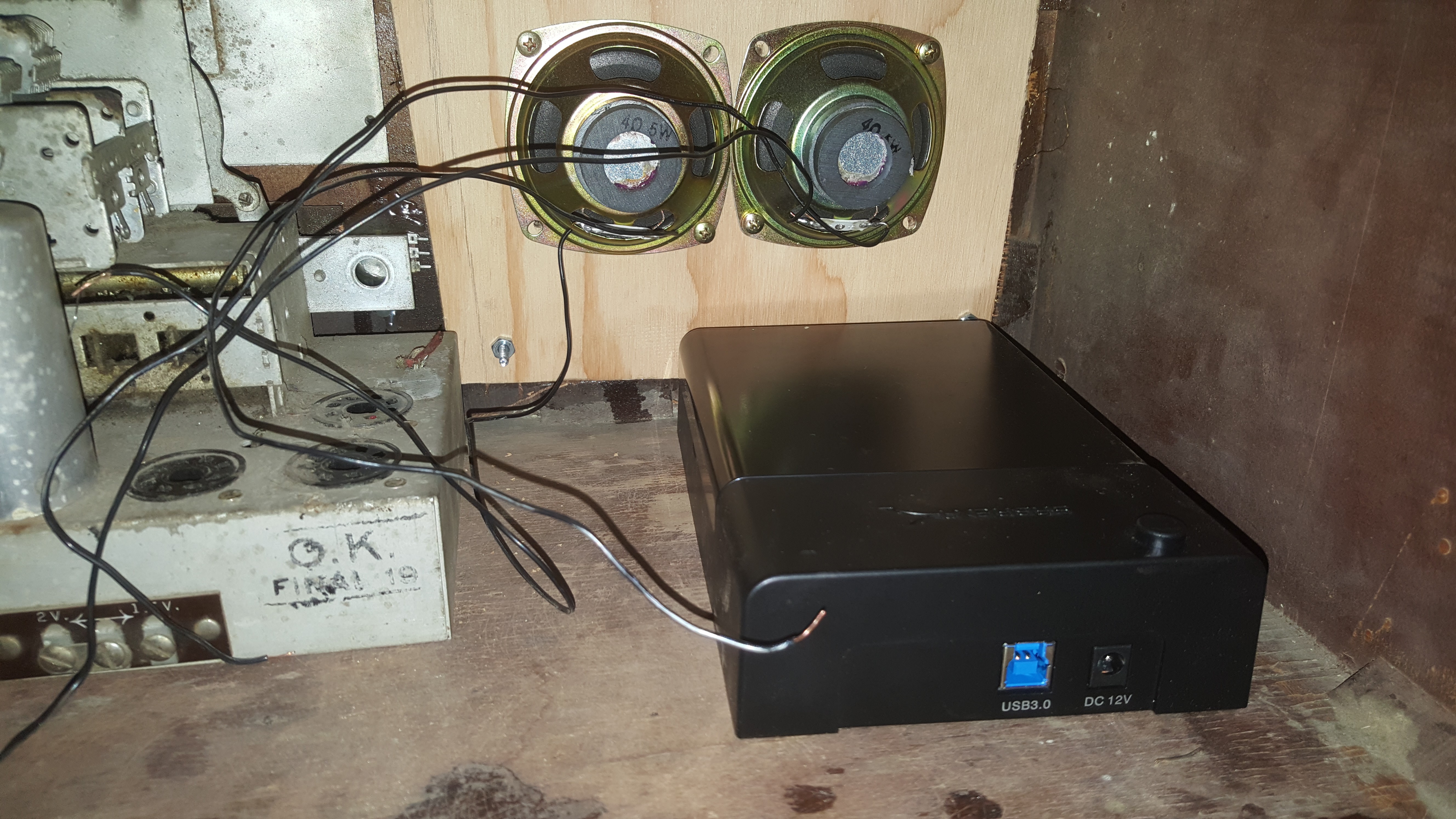
i started with the hard drive since it's by far the largest component in this assembly. I also decided pretty early that this was what i was going to mount the pi and the audio board on top of, since it has so much real estate being wasted on its top.
![]()
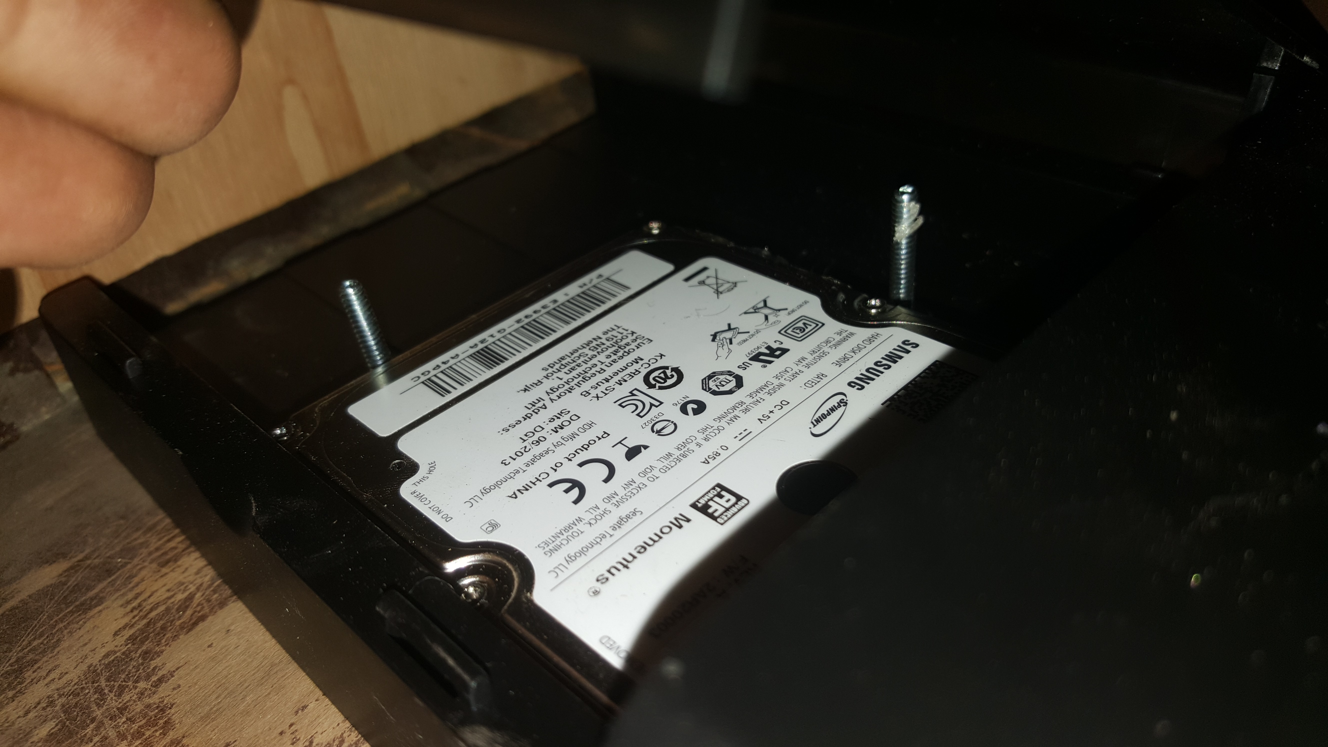
the hard drive dock is held by screws which come up through the base. The nuts on these screws serve a double purpose:
first they hold the hard drive dock firmly to the base, preventing it from moving.
second they hold the hard drive itself firmly against the connector ensuring that it won't be bumped out of place which would cause the entire radio to stop functioning.
![]()
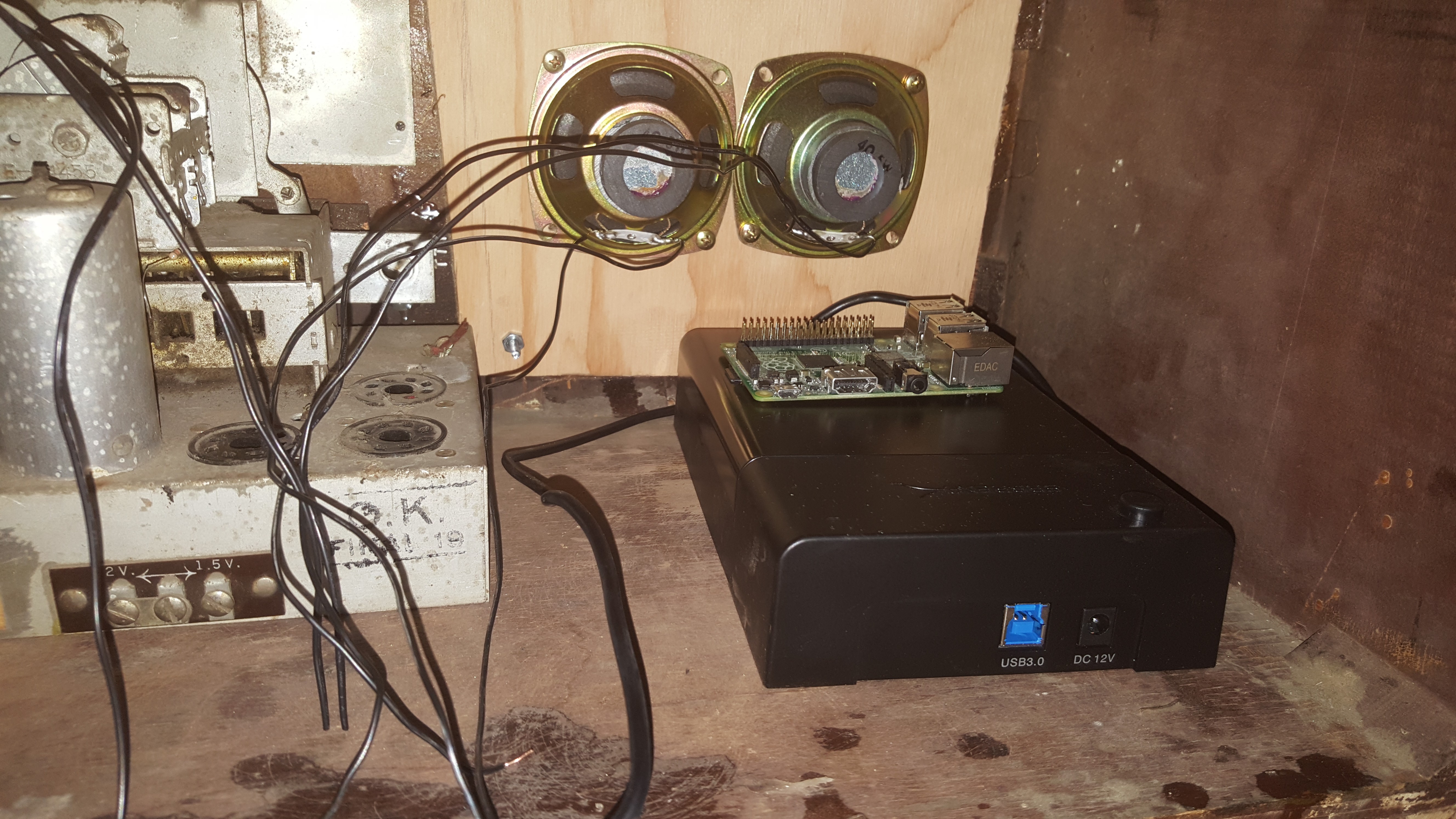
mounting the pi was simple, i just picked a spot and hot glued it down. I know that it has mounting screws but for my purposes this was much quicker and it got the job done well.
![]()
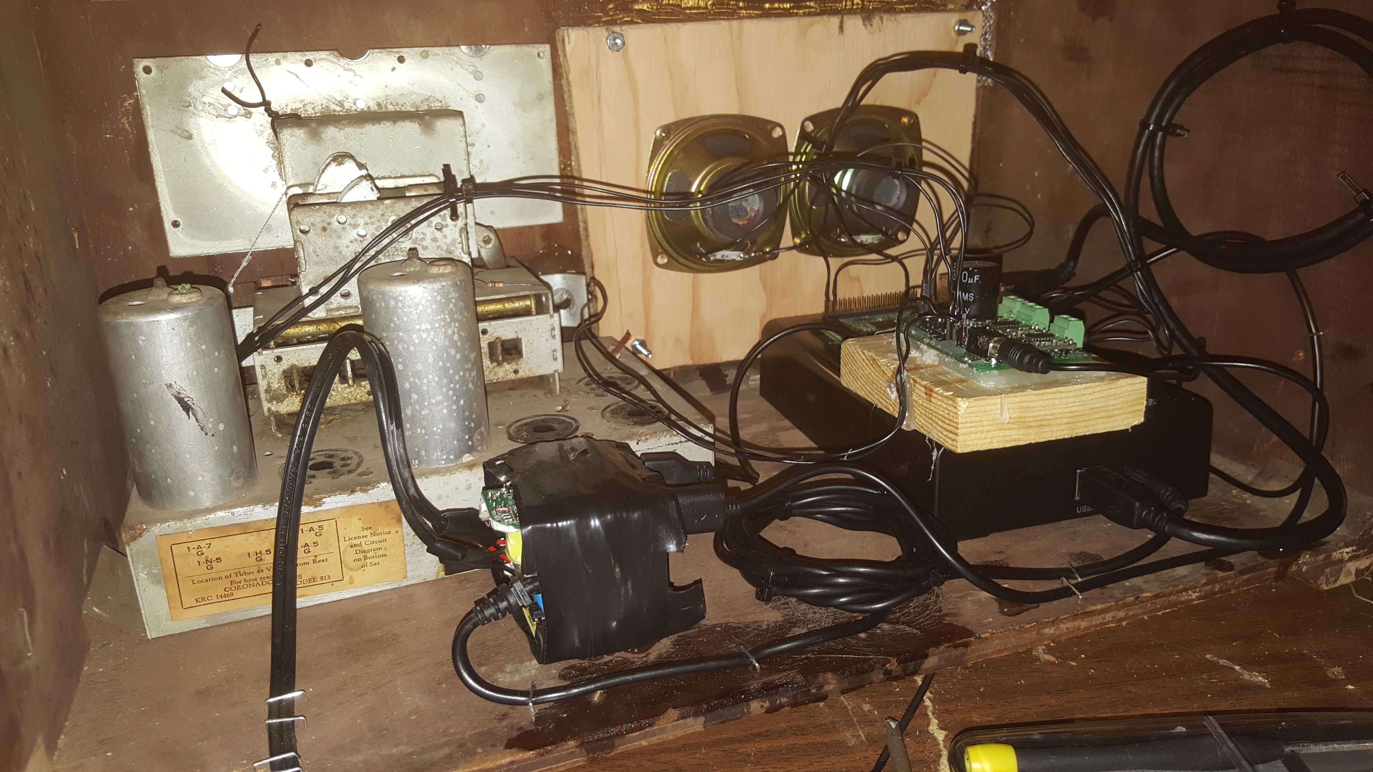
i really hate to skip steps like this but i forgot to take pictures at this point in the project. I next added the audio board which i completed in a previous log. this takes 5v in which isn't hard to come by, and in combination with the power demands of the pi, makes a great board for this project. The power source for this entire project comes in the form of that block of electrical tape. Inside there are two different wall warts, one is a 4 USB phone charger and the other is a 12v dc adapter for the external hard drive. Both are wrapped (mostly) safely in the electrical tape and hot glued to the base. power is run directly from those two boards and into the rest of the radio. at the end of the day everything functions perfectly.
Everything was cleaned up using a staple gun and zip ties, i did my best to manage the wires, and i feel pretty confident that i did a good job here.
![]()
the final product looks fantastic! if anyone wonders whether the thing is actually working, check the files on this project's hackaday.io page, i included a quick webm of me changing the volume and songs on the radio using the knobs.
thanks to everyone who followed this project, i hope that it lived up to your expectations, i know it certainly did mine.
-
Minor Restorations To The Front Of The Radio!
09/05/2016 at 05:29 • 0 comments![]()
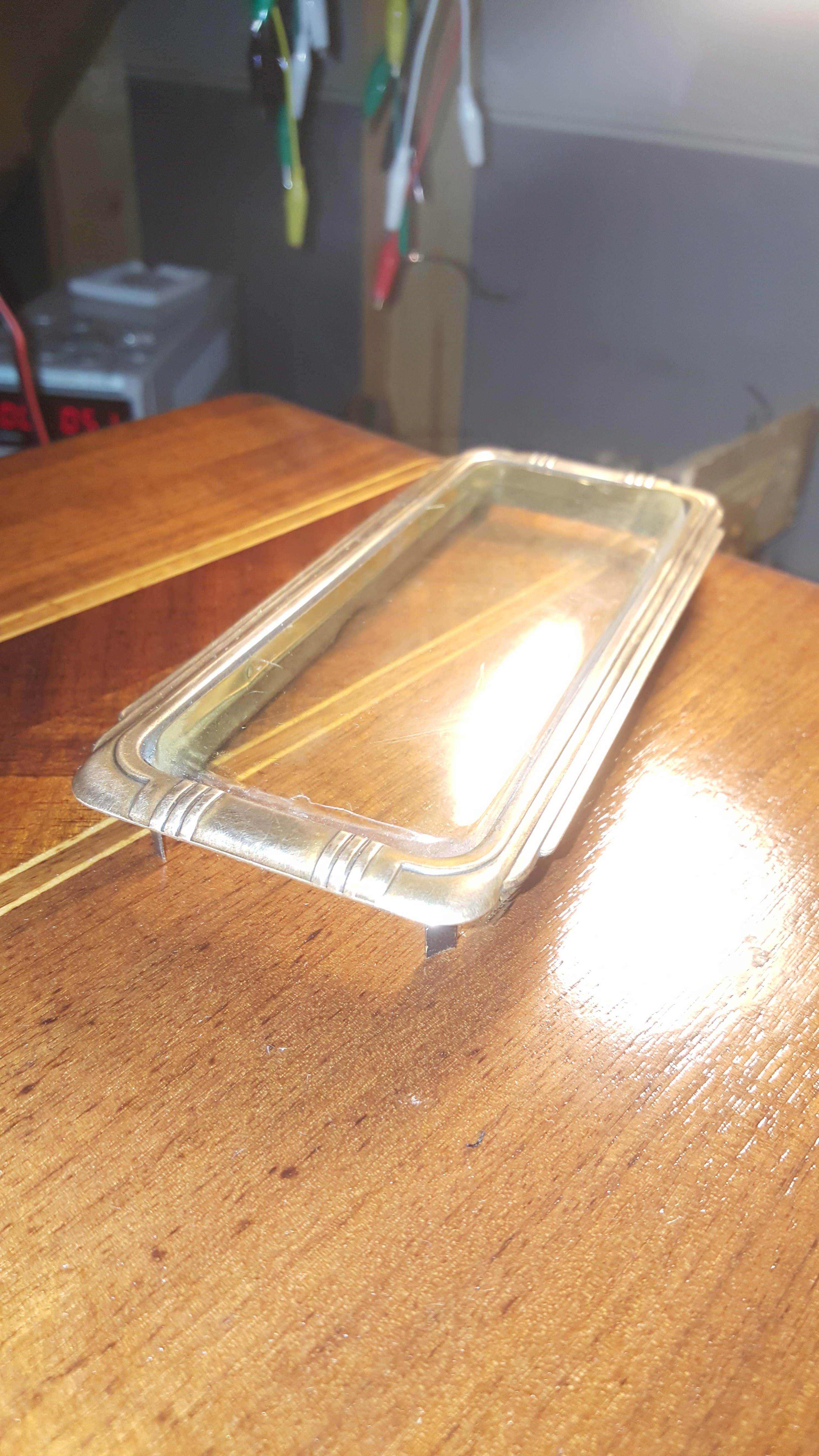
this is where we left off in the last project log, the speakers had just been attached. Anyone who's been following this project will notice that the orginal radio came with brass trimmings around the tuning needle and above the mechanical station select (what i presume it to be, it never worked when i got it).
![]()
when i first got the radio these were in pretty bad shape. The plastic over the tuning needle was pretty foggy and the brass on both trims was dirty and tarnished.
![]() i managed to restore the first trim pretty well using some steel wool and headlight cleaning compound, i think that's as close as i'm going to get it to brand new. some high grit sandpaper would probably give it a nicer finish and even get more crud out, but given the thickness of this brass i don't want to make it weaker than it already is.
i managed to restore the first trim pretty well using some steel wool and headlight cleaning compound, i think that's as close as i'm going to get it to brand new. some high grit sandpaper would probably give it a nicer finish and even get more crud out, but given the thickness of this brass i don't want to make it weaker than it already is. ![]()
the other brass part didn't clean up nearly as nicely, but it did manage to gain some nice highlights that i think work well when everything's assembled.
![]()
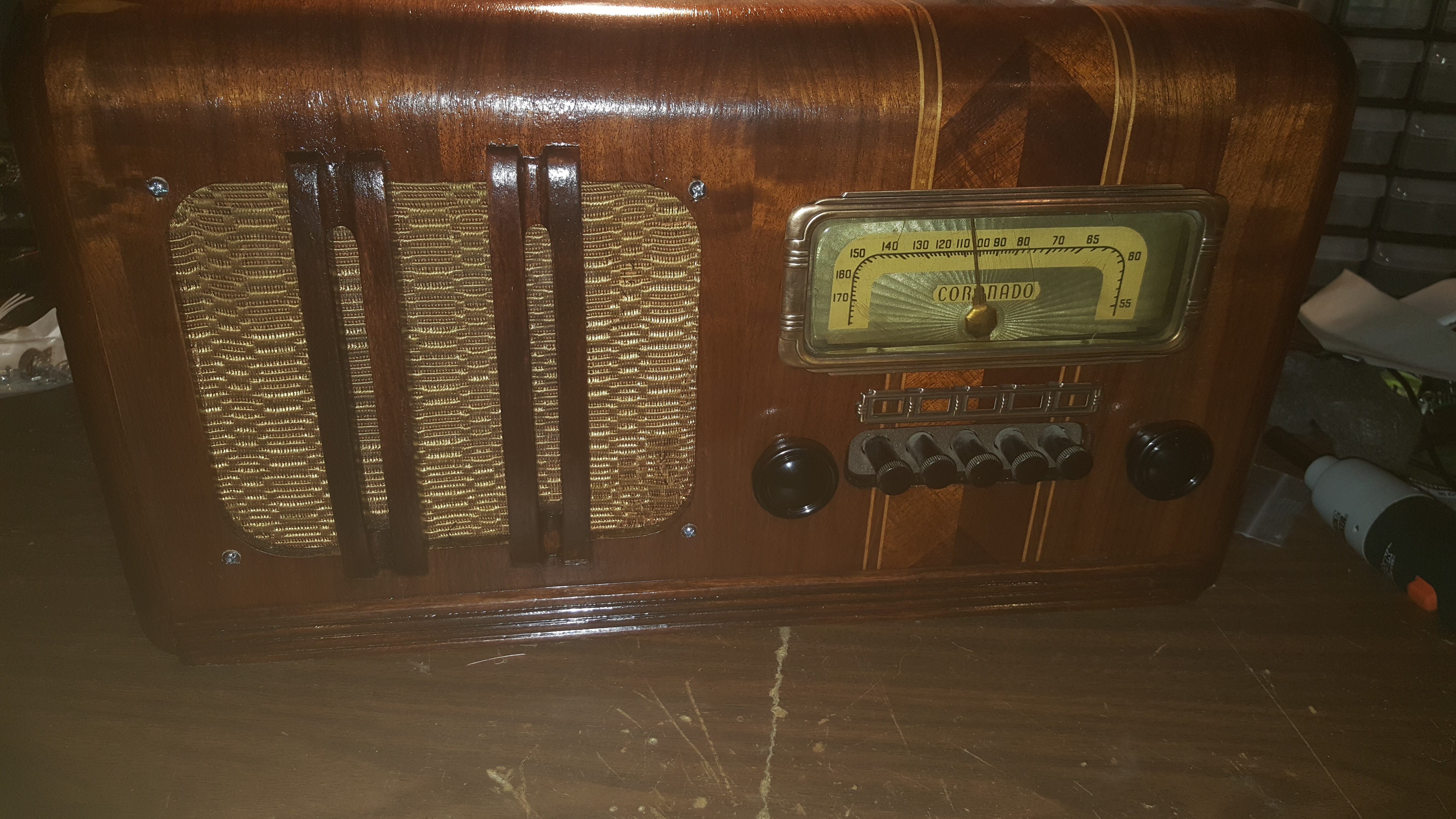
Finally i brought everything together, including the original internals which I've modified to work with the circuitry i'm adding into this project. Add some knobs that i found on ebay for a decent price and we have the front part of the radio complete.
-
Speaker Mounting
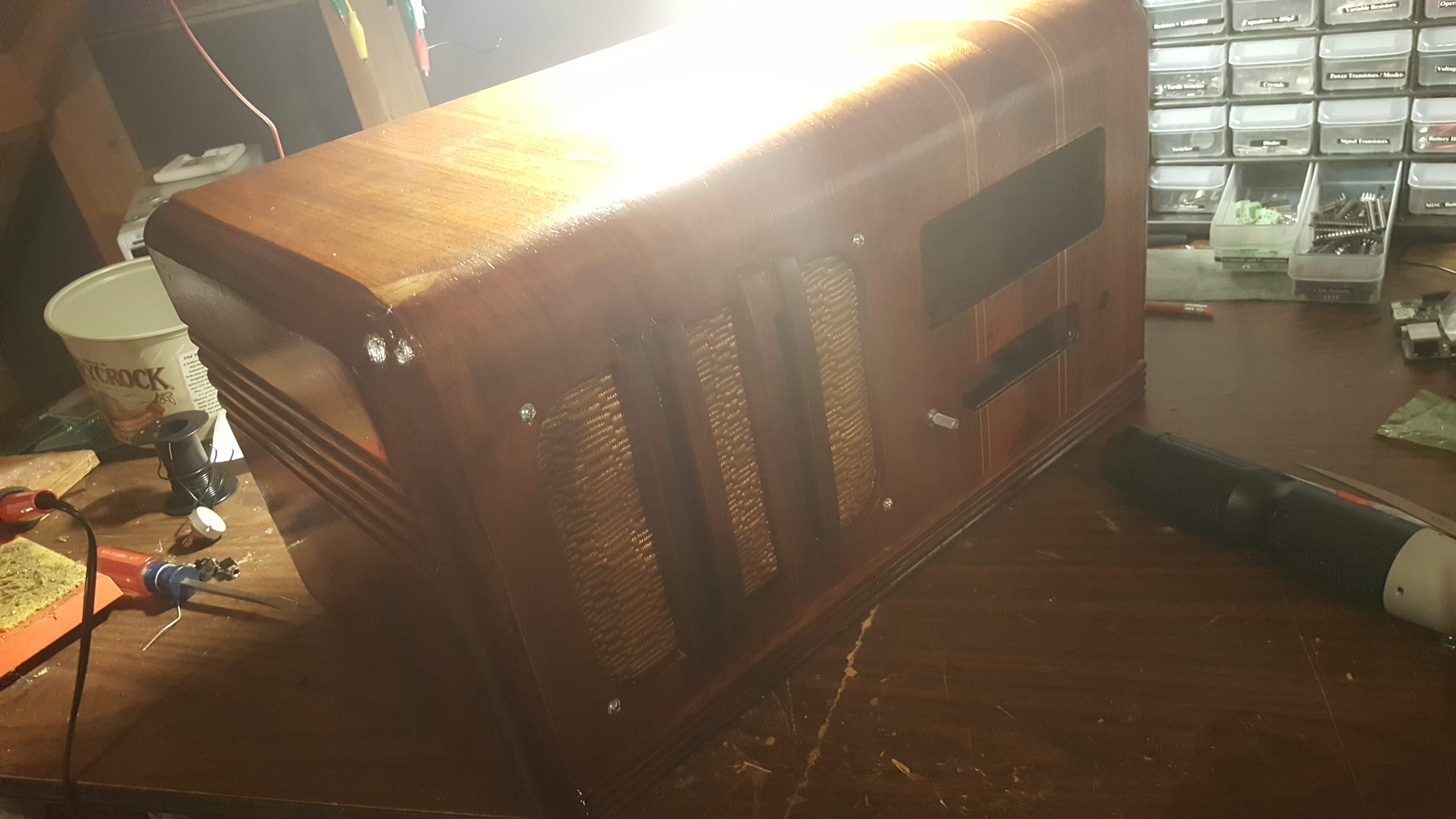
09/05/2016 at 05:18 • 0 commentsthe project was actually finished today but i think that i'm going to split up all the steps i took into separate logs, just to prevent having one massive log. first things first i added two more coats of polyurethane, although this image doesn't show it very well on account of the awful lighting it is noticeable in person.
![]()
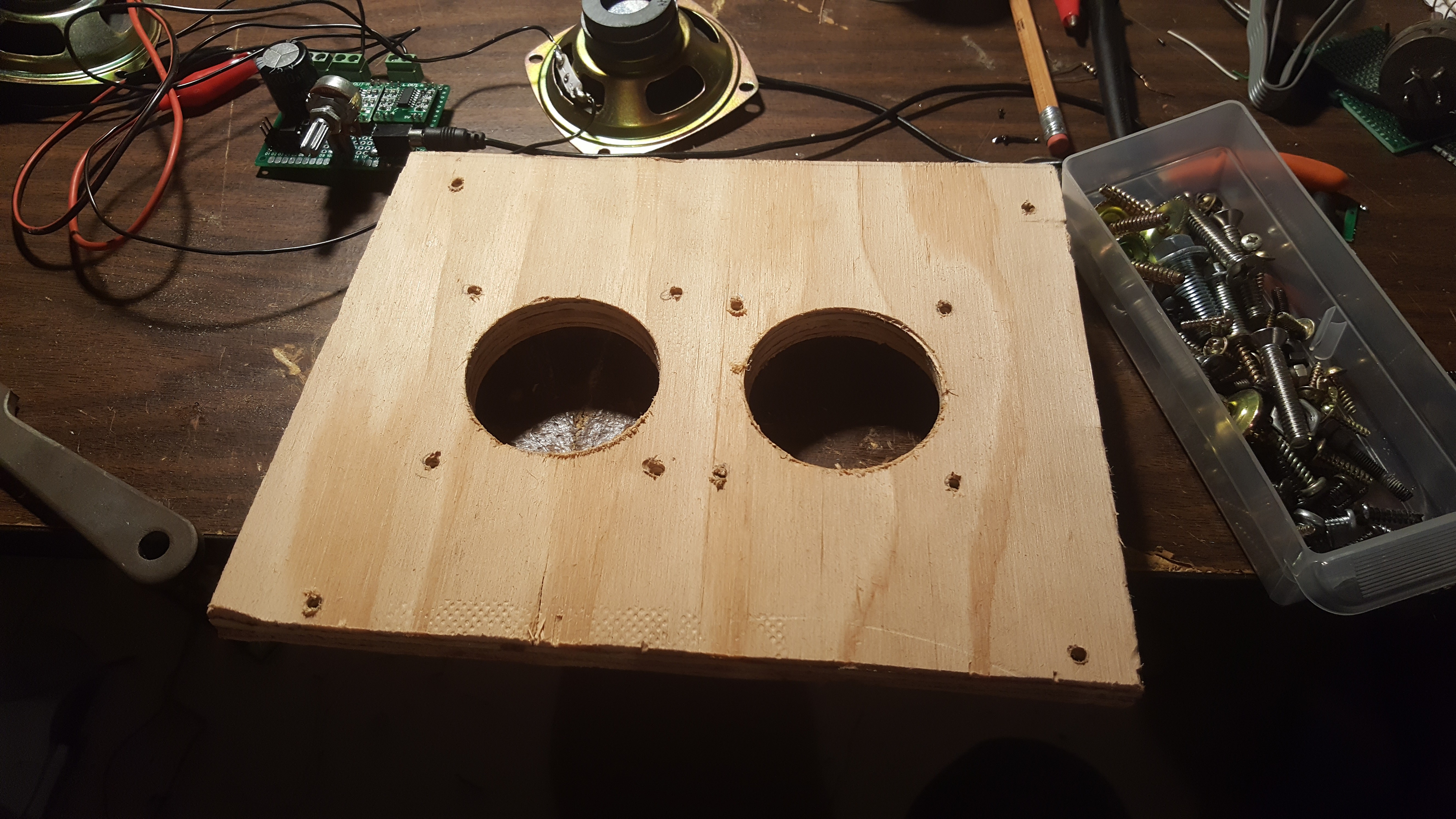
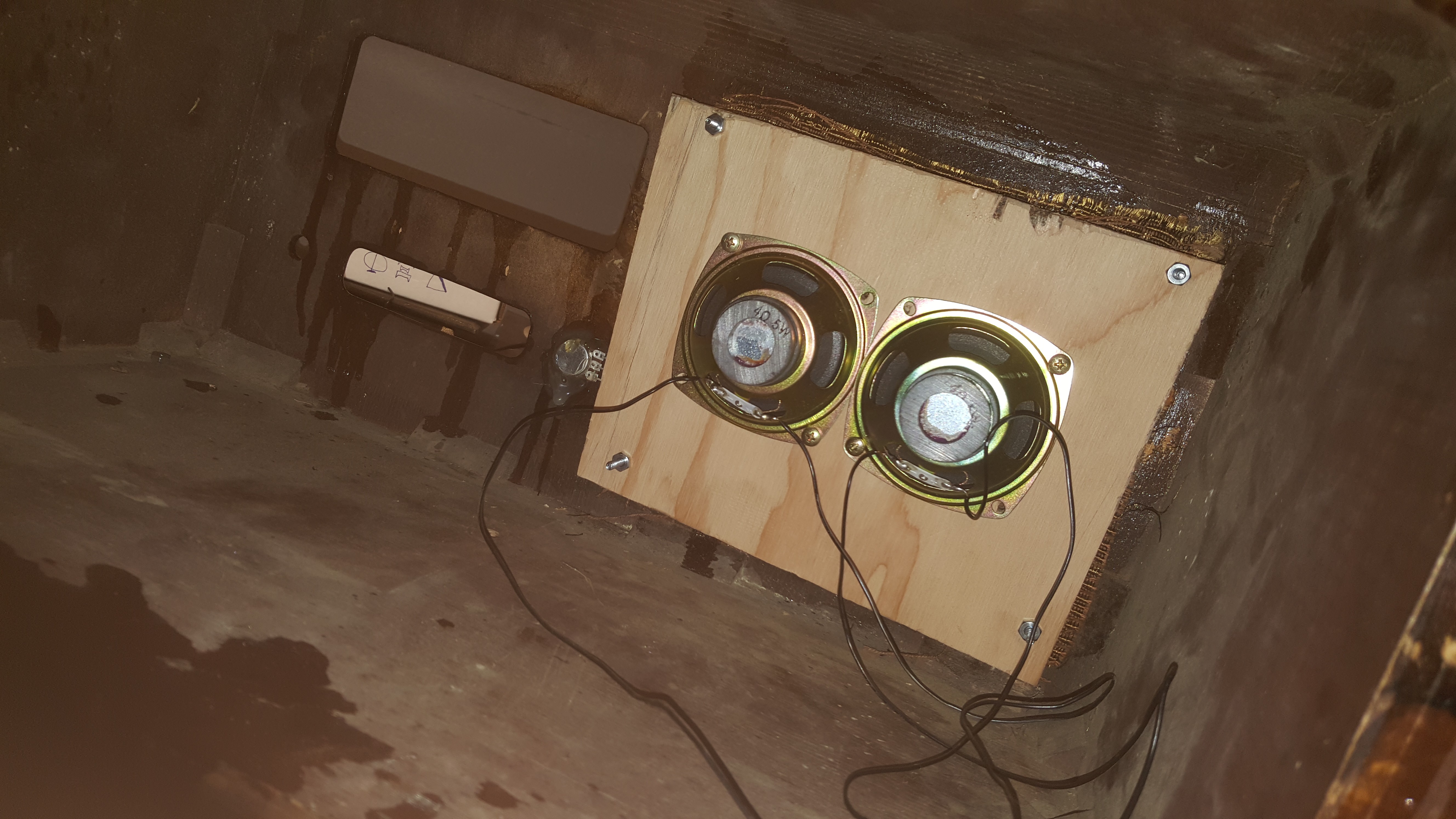
The speakers are both mounted to a piece of half inch plywood which has nuts to hold the wood tight to the front of the radio. here's a picture with this entire part of the project completed.![]()
![]()
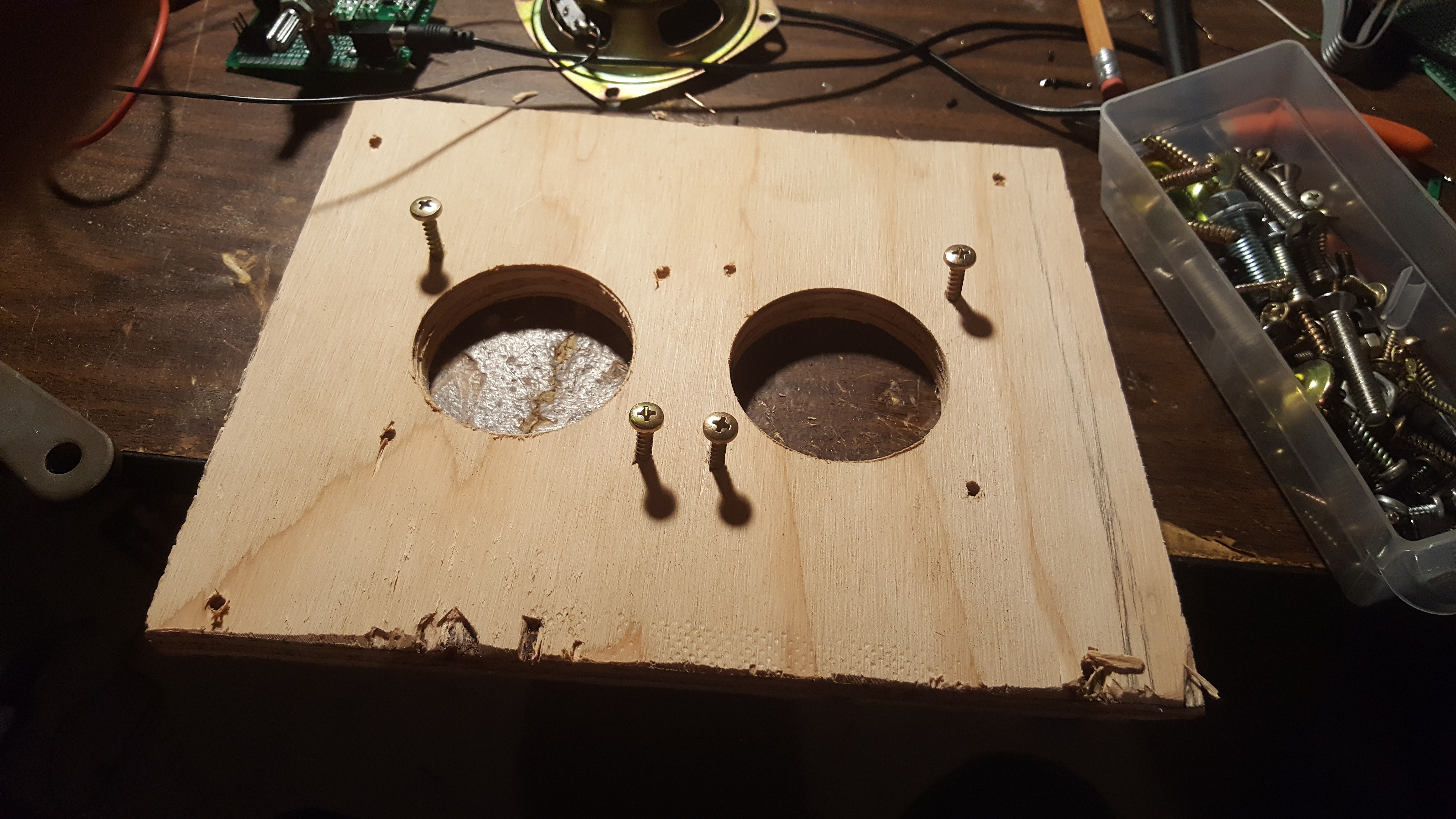
i started with the plywood, then marked out and drilled the appropriate holes.
![]()
found some screws.
![]()
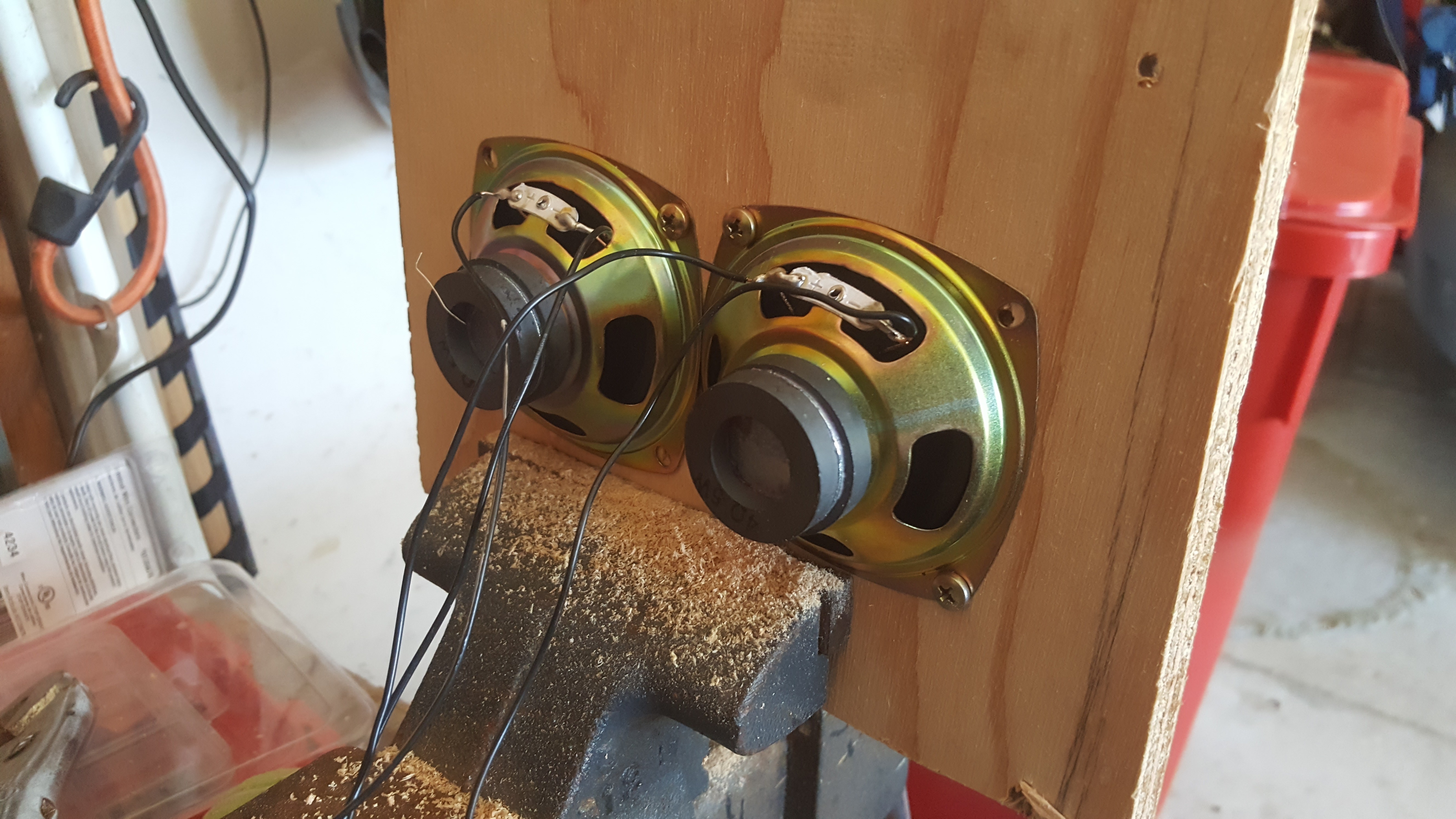
and mounted the speakers.
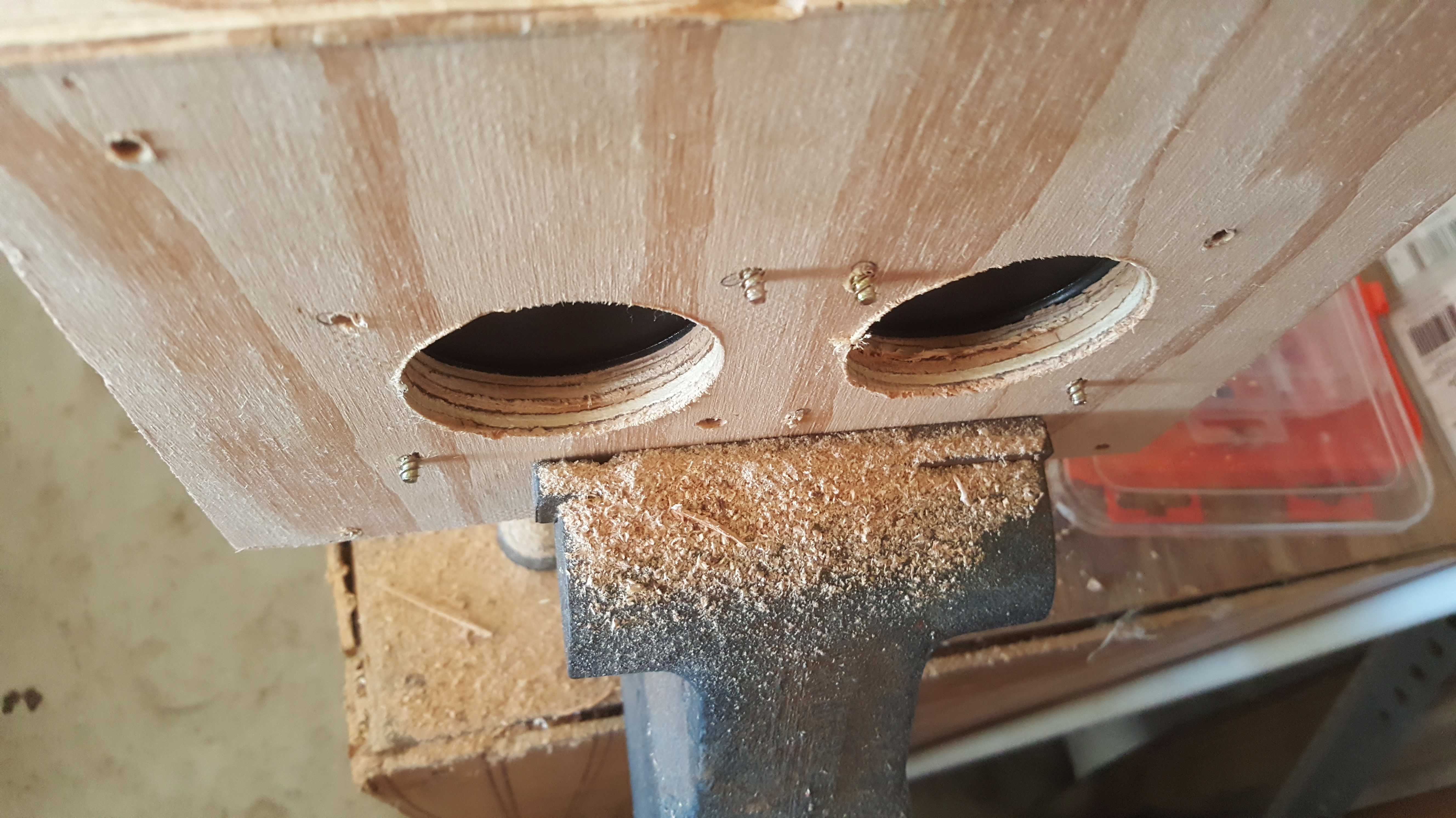
![]() the only thing left to do on the speaker assembly was to flatten these screws which would definitely poke holes in the grill cloth.
the only thing left to do on the speaker assembly was to flatten these screws which would definitely poke holes in the grill cloth. ![]() its not very clean but it gets the job done, plus the wood here won't even be visible from the outside due to the grill cloth.
its not very clean but it gets the job done, plus the wood here won't even be visible from the outside due to the grill cloth. ![]()
i put the screws in first, then ran the grill cloth over the screws to ensure that it stayed even. the grill cloth was then held down by putting the speaker assembly on behind it which firmly holds it in place. some nuts keep everything in order.
![]() Everything came together pretty well, the grill cloth is both supported and held in by the plywood to its back and both the speakers are held in tight. in the next log i'll go over some of the smaller restorations i made to the front.
Everything came together pretty well, the grill cloth is both supported and held in by the plywood to its back and both the speakers are held in tight. in the next log i'll go over some of the smaller restorations i made to the front. -
Audio Board Complete
09/04/2016 at 06:10 • 0 comments![]()
![]()
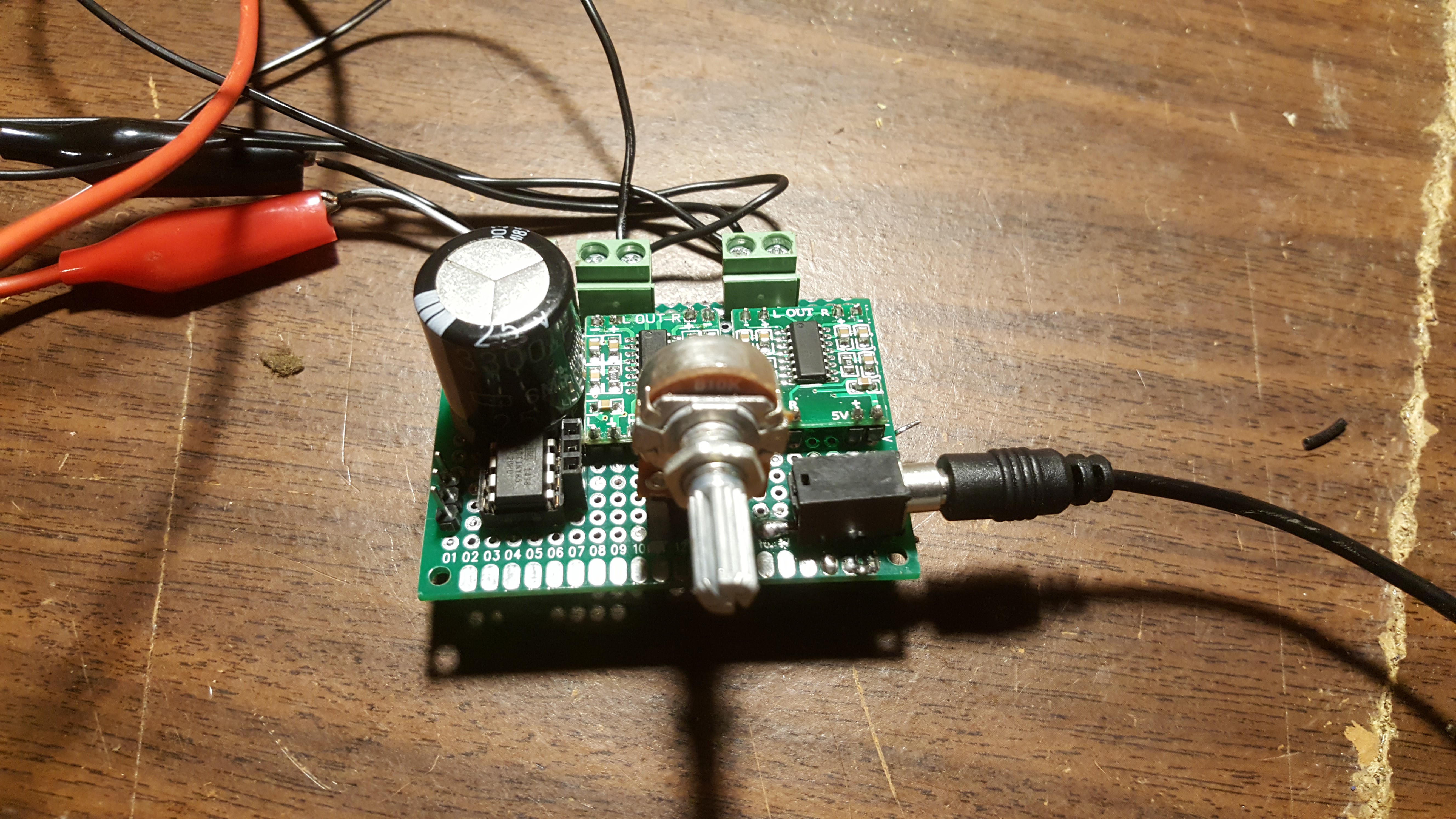
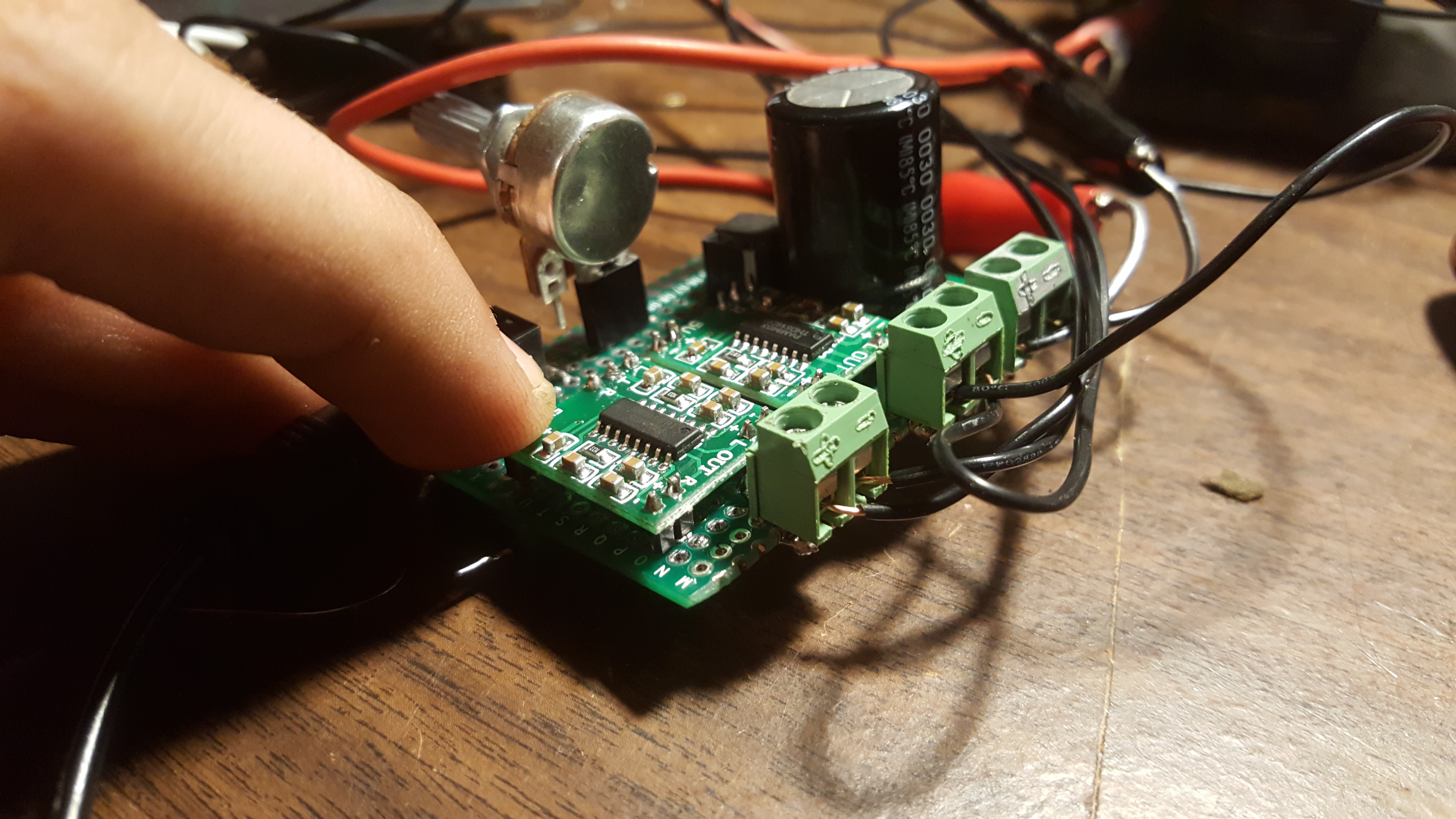
audio control on this project has been my biggest enemy, i tried for awhile to have it controlled on the PI (which would have been a much better solution) but ended up with just building a circuit for it. Even this one isn't very clean, currently it has a few issues with the volume, notably the fact that i only have 10k pots laying around so the range on the volume is entirely controlled by the first quarter turn. and the two boards are slightly redundant, i had much better results on my breadboard by running two modules each with a different channel. the volume is controlled by a pot which essentially just shorts the signal to ground in varying degrees and prevents it from getting to the modules (the pots going to be mounted to the inside of the radio and not the board, the header is for wires to come in). the connectors make the hookup nice and easy. All and all i'm decently happy with this board, its hit the point of "good enough" for this project, especially considering the quality of the audio from the archive.
i also forgot to mention that the attiny sitting in the corner is its own circuit, its for communication to the PI. it just activates a pin when it detects a significant change in the pot its connected to. the entire attiny circuit runs on 3.3v directly from the PI.
all that's left to do is to put the circuit in the radio box and see how it all works together, hopefully there's more project logs comming!
-
Nearly There
09/02/2016 at 05:30 • 0 commentsThis project has had way more setbacks then i ever thought were possible. For the last week or two I've been trying to work with the pi to control the audio on the speakers. Unfortunately the player i'm using (omxplayer) doesn't support volume control during the playing of a song. Also every python wrapper i attempted to use with it seemed to have little to no documentation on the functions i needed or flat out these functions didn't have any code in them when i looked at the source.
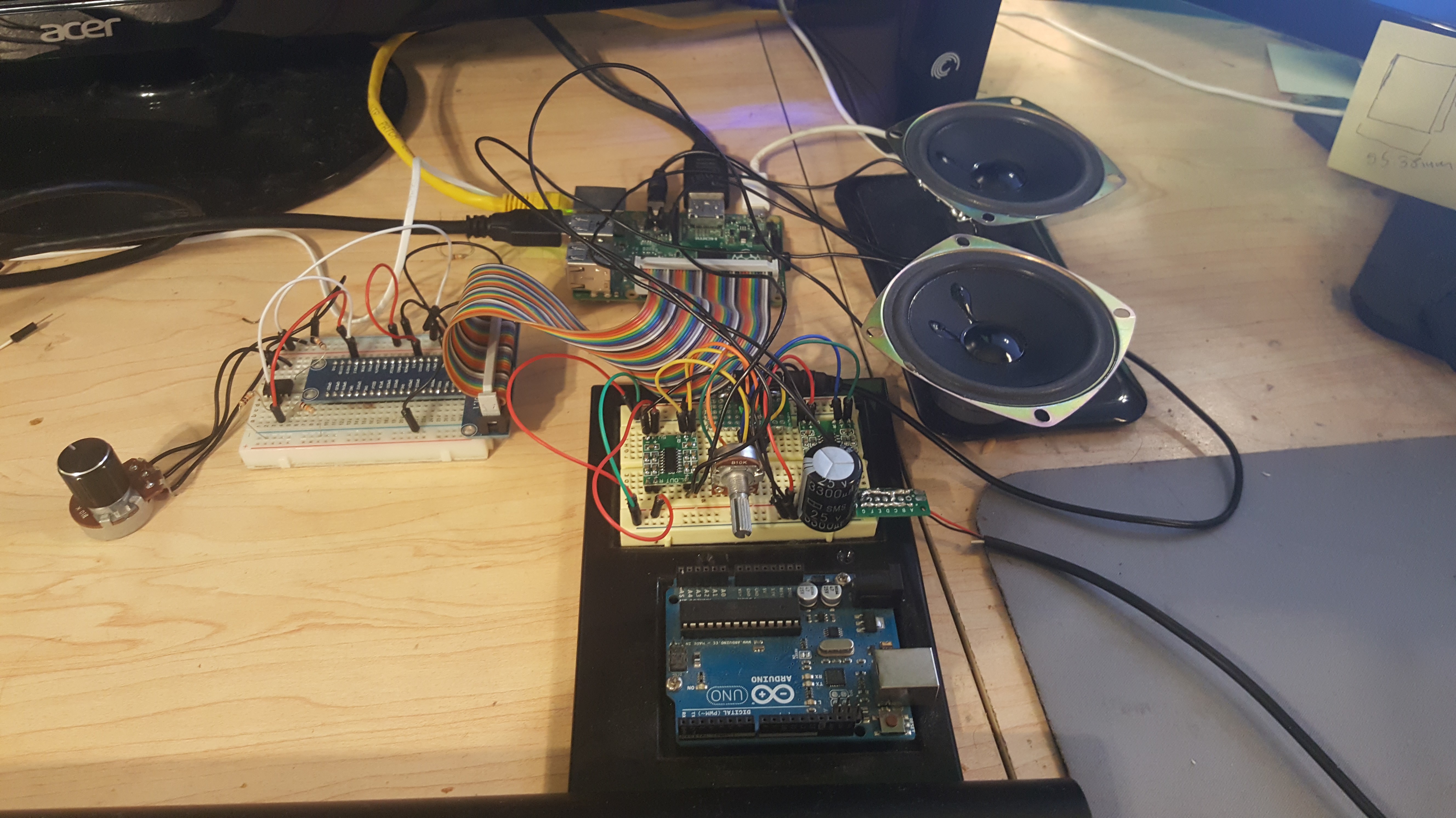
either way the electronics are as complete as i'm going to make them for the time being. The speakers are controlled by two PAM8403 each handling 1 speaker. Technically these can handle both speakers with ease but I've gotten better results sound quality wise by doing this. I'm pretty sure it has everything to do with the circuit surrounding the board and not the boards themselves, but i'm pretty eager at this point to get everything together and have this radio on my desk.
other than that everything seems to be in perfect order. My next update will probably have the boards soldered and everything ready to be put into the box. see you then!
![]()
-
General Update
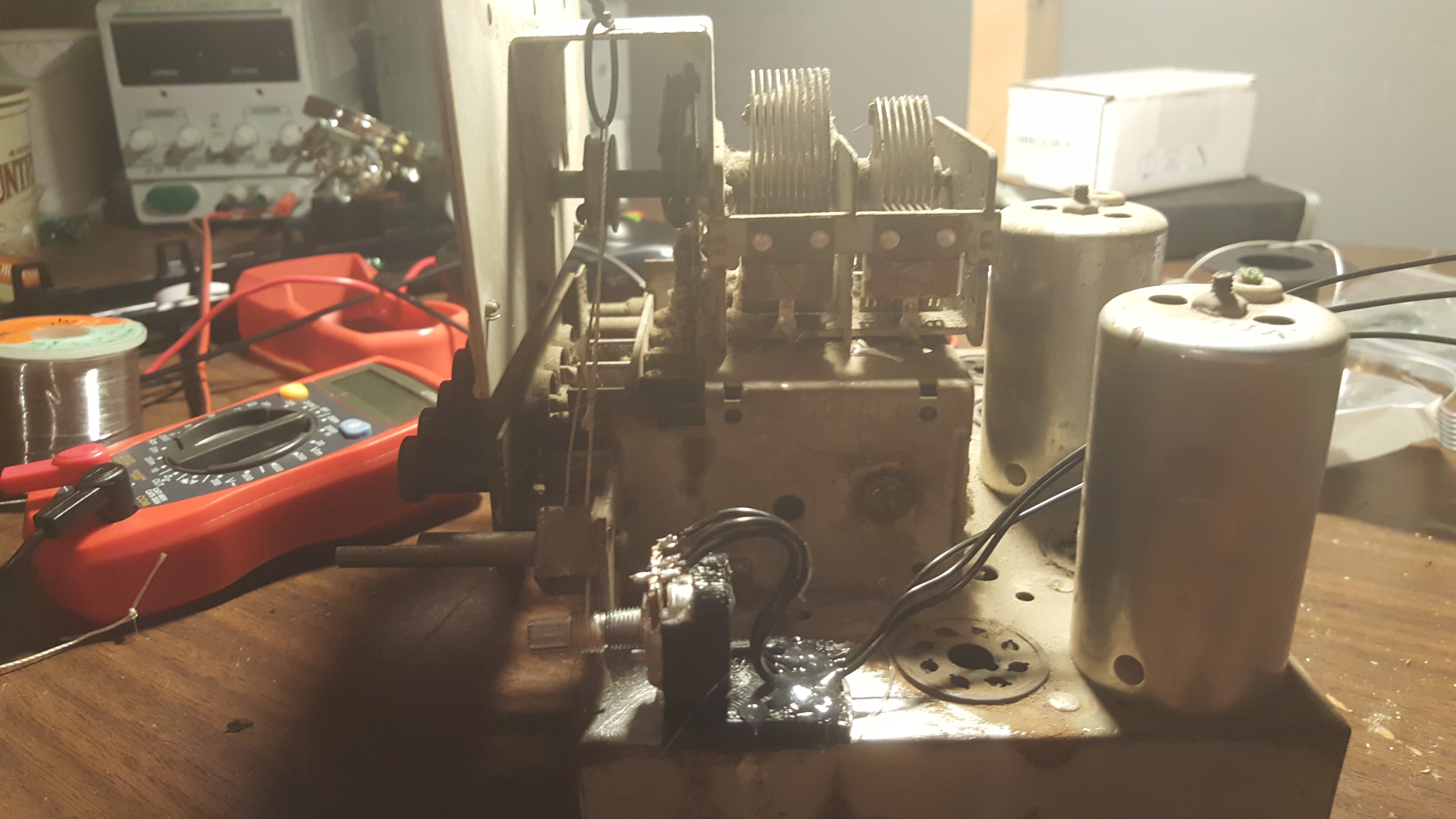
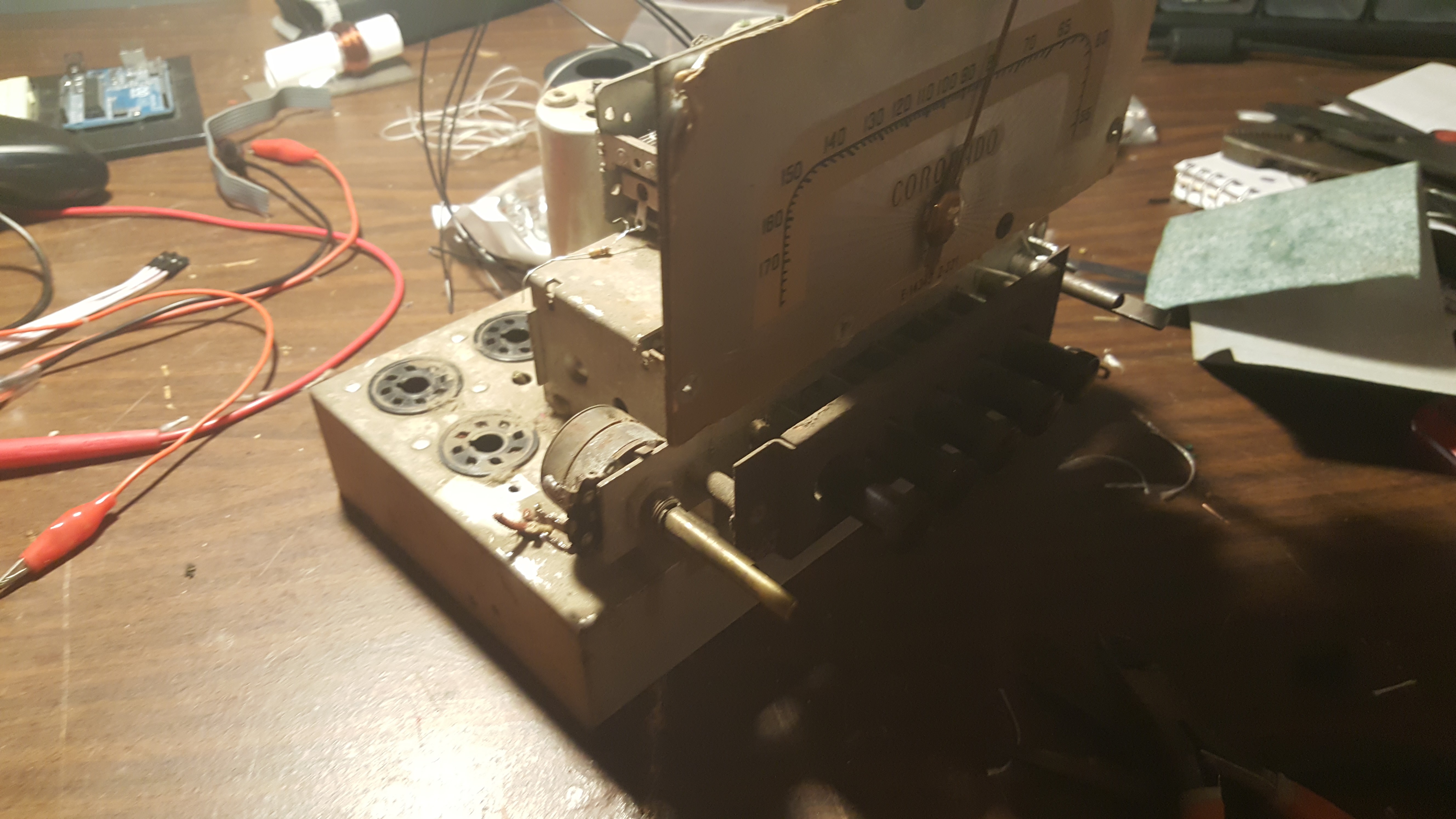
08/15/2016 at 06:22 • 0 commentsIts been a week since my last update, currently the project stands somewhere past halfway completion (fingers crossed). I'm attempting to keep the finished project looking as close to the original as possible, because of this i've decided to use the original dials and buttons for a control interface. When i got the radio the string which connected the tuner knob to the needle and the rest of the radio's tuner circuitry broke, I've since repaired that.
in addition to that I've also added a potentiometer additionally attached to the wheel which controls the needle. My plan from the start was to use the tuner knob as a kind of shuffle button so that it will pick a random track whenever the knob was turned.
![]()
the rest of the work was just some small soldering and wire clipping. a lot of the internal circuitry still exists inside the metal box but i don't see any reason to remove it.
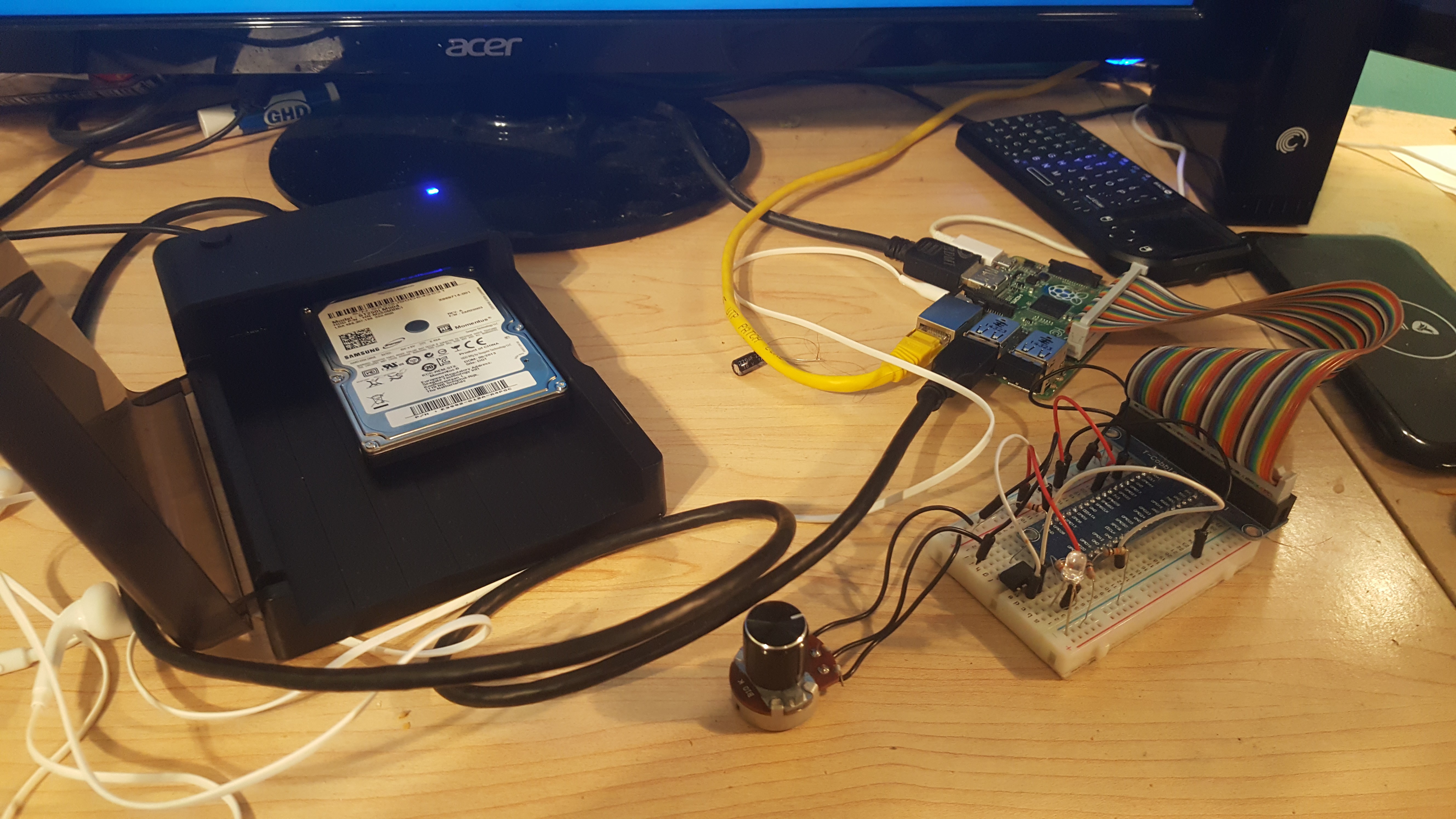
for the most part the radio box is ready to go, all that is left is the code for the pi and the audio system for which i'll be using a PAM8403 (or maybe two) along with speakers salvaged from old CRT TVs, which i am in no shortage of.![]()
![]()
the circuitry for the pi could be better. Due to the pi's lack of audio reading capability I've opted to use a attiny85 as a makeshift ADC for the two potentiometers which will control the song shuffling and the volume. all and all it works pretty well, along with that I've opted to use a desktop drive dock which I've thrown a salvaged hard drive into to store the music. I've also managed to download the music archive (at least all the mp3 files) which is in total 85GB. the hard drive and the code running on the attiny work perfectly as they're suppose to. I've had many setbacks with the pi however, mostly having to do with the audio player I've decided to use OMXplayer and its lack of code control-ability and the inconsistent reliability of wrappers for it. I'm hoping to find something better soon but i may just have to make due.
-
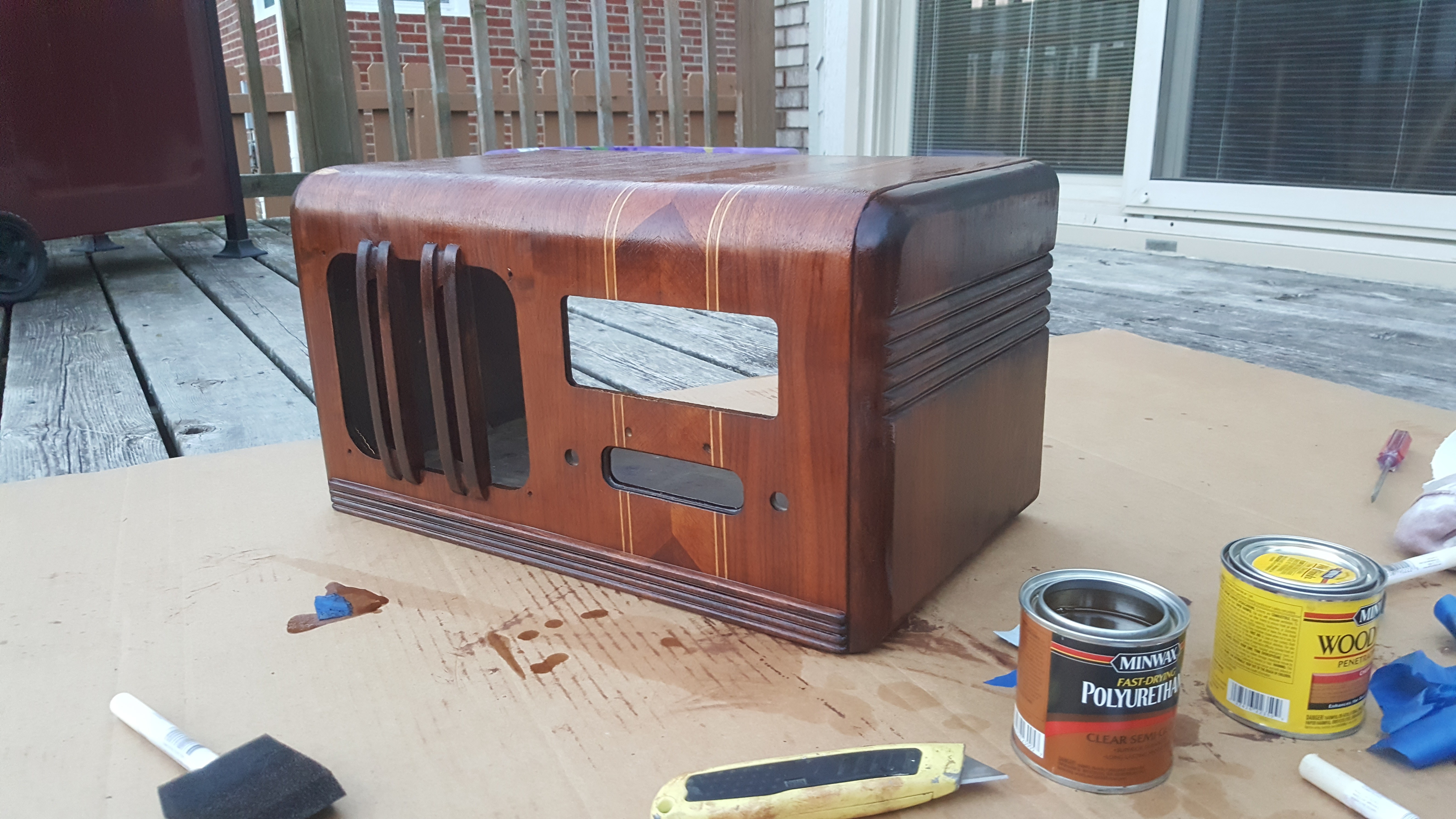
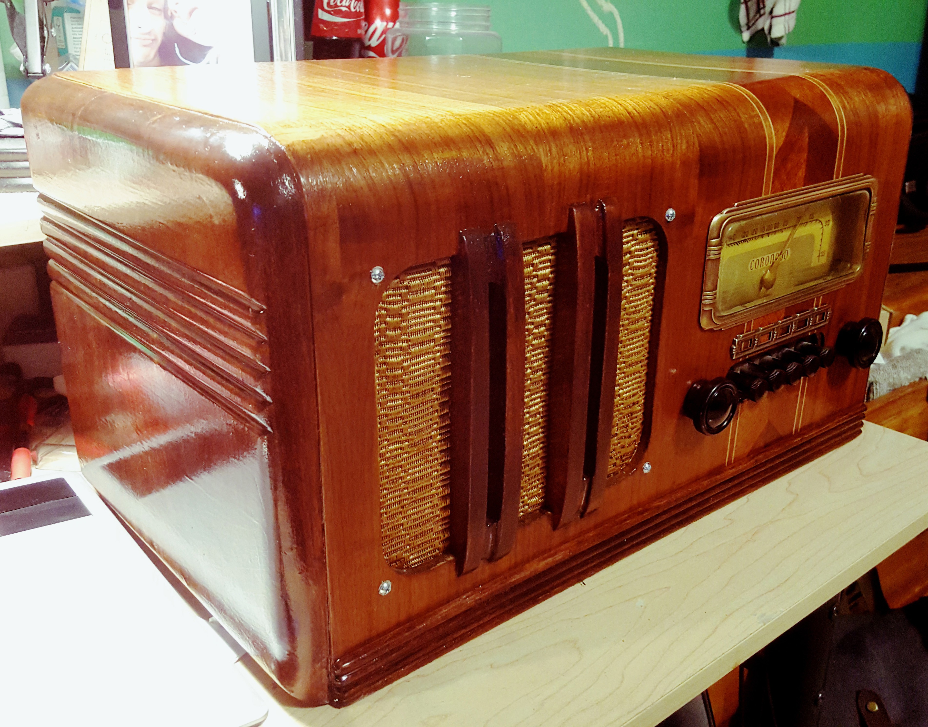
Stain and Finish
08/06/2016 at 08:09 • 0 commentsthe new stain and finish is on. I opted for a two color finish to match the original a bit more closely and added a polyurethane coating to protect the wood. Now its time to start working on the electronics
![]()
-
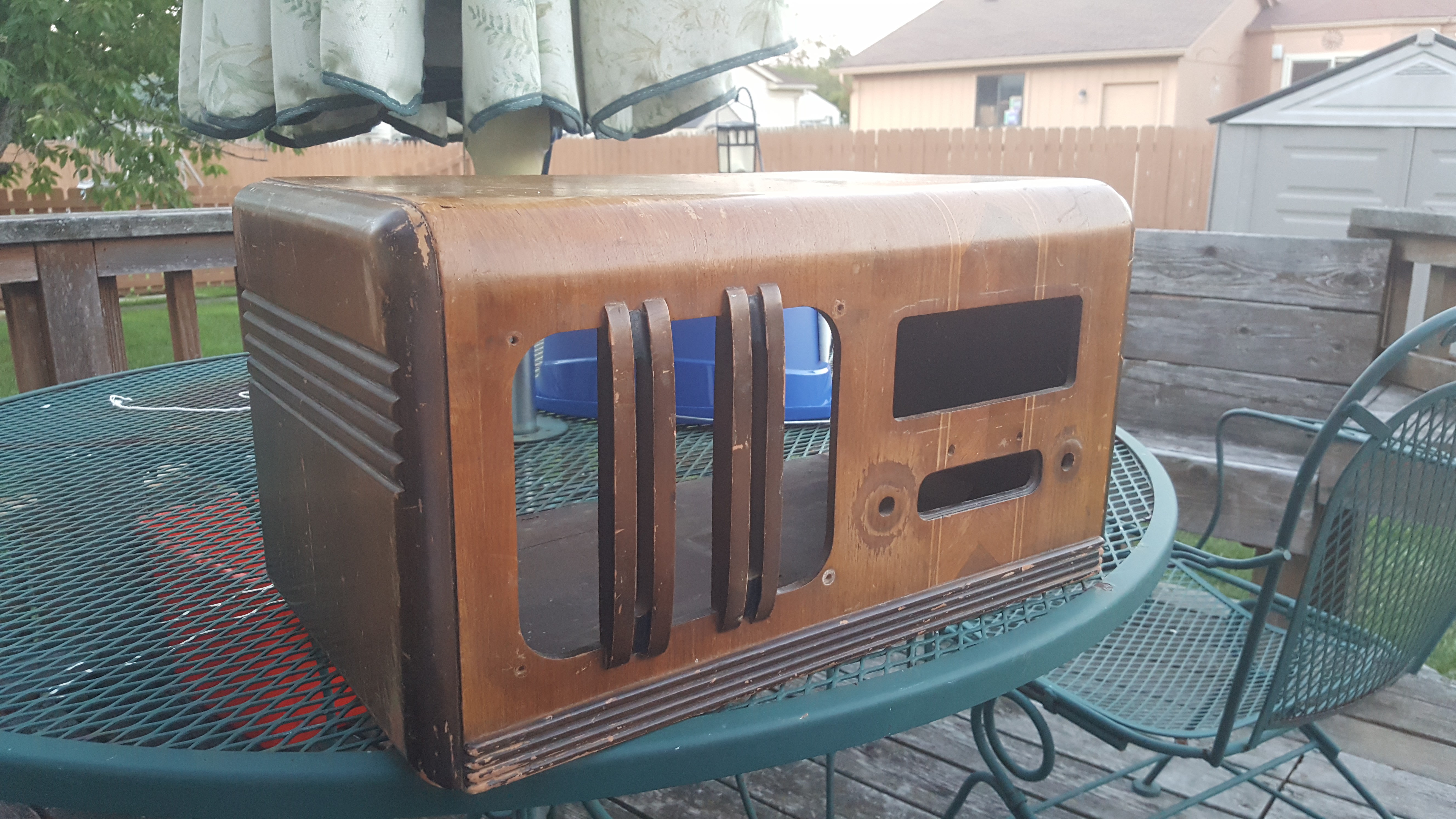
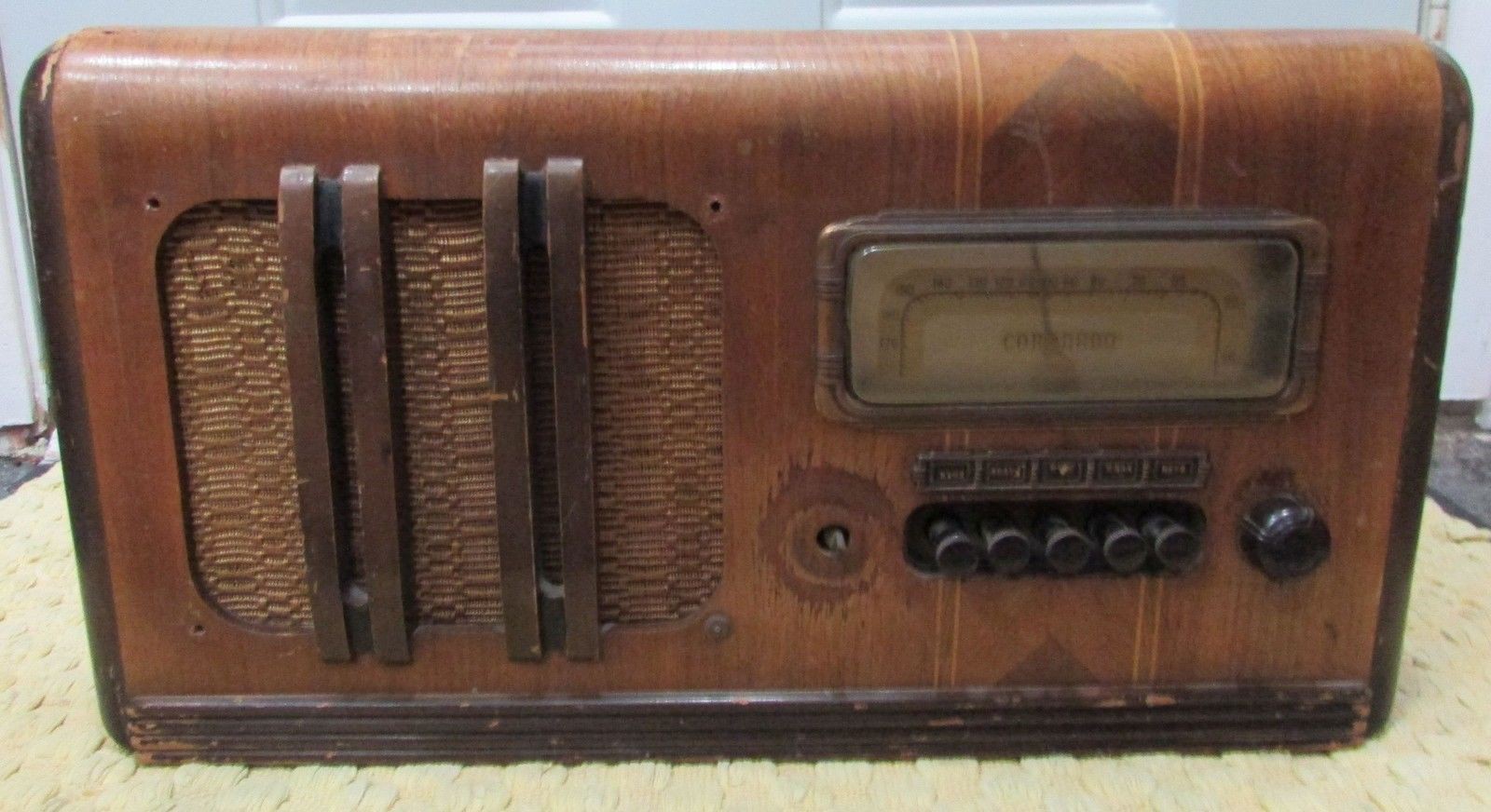
Original Finish Removed
08/04/2016 at 05:59 • 0 commentsthe previous finish has been removed, along with the internal components (For the time being). It's now ready for refinishing. The first photo is what it looked like before i removed the original finish and after. It makes me hopeful that this will come out looking almost new again when the project is finished.
![]()
![]()
Raspberry Pi Jazz Radio
The old radio to play old songs on new hardware

 i managed to restore the first trim pretty well using some steel wool and headlight cleaning compound, i think that's as close as i'm going to get it to brand new. some high grit sandpaper would probably give it a nicer finish and even get more crud out, but given the thickness of this brass i don't want to make it weaker than it already is.
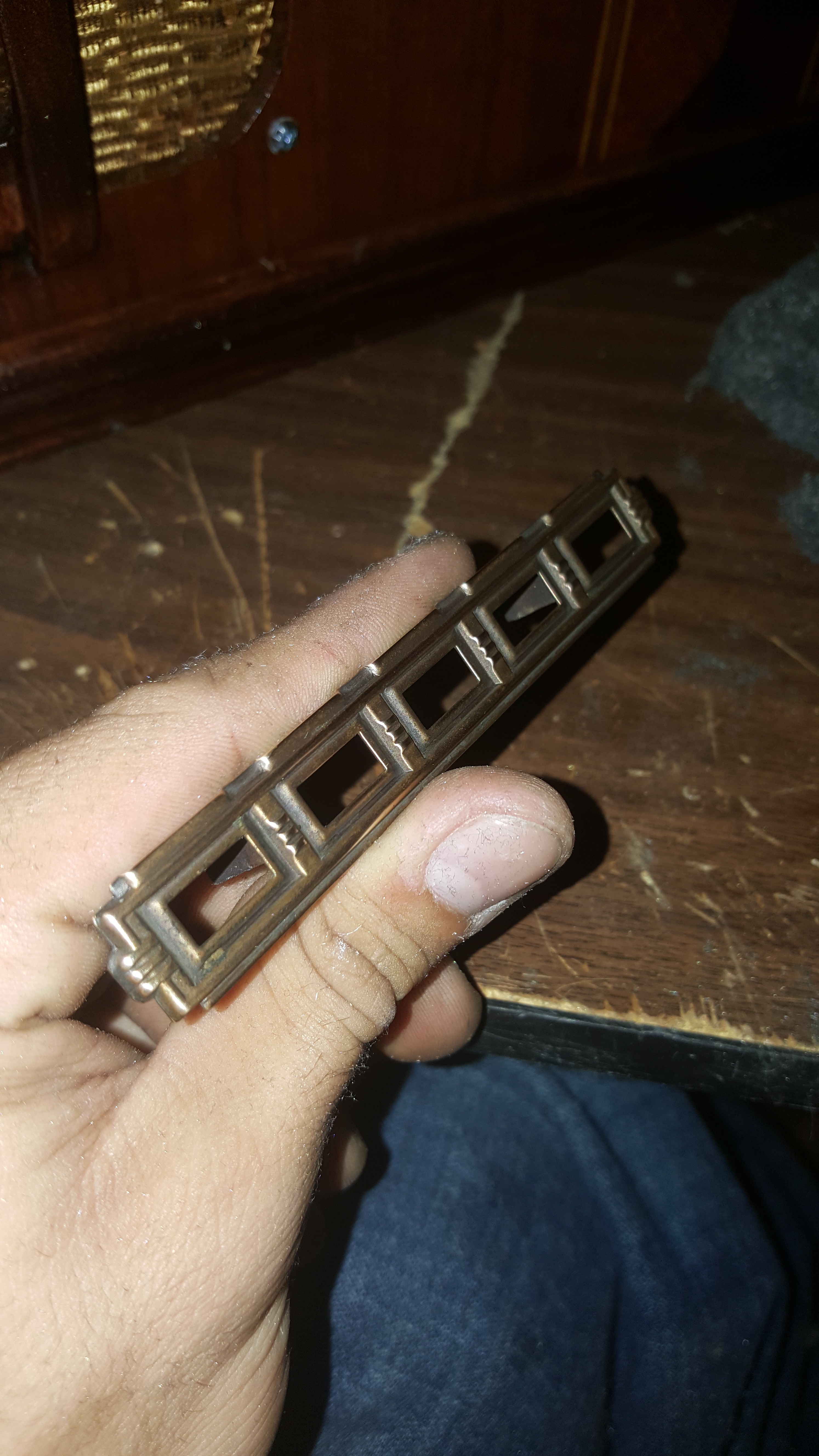
 the only thing left to do on the speaker assembly was to flatten these screws which would definitely poke holes in the grill cloth.
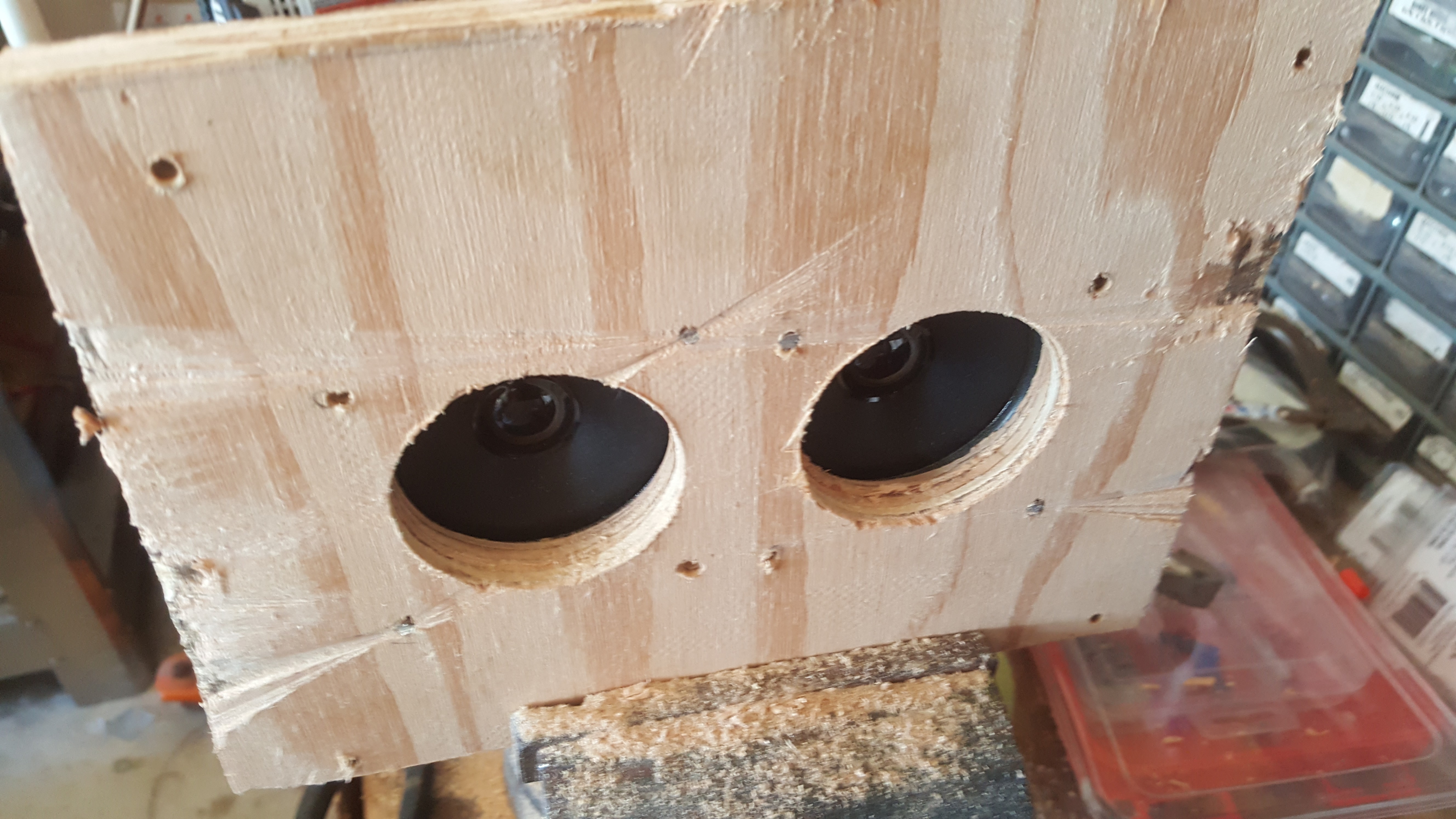
 Everything came together pretty well, the grill cloth is both supported and held in by the plywood to its back and both the speakers are held in tight. in the next log i'll go over some of the smaller restorations i made to the front.