Many times we face the need of reverse polarity protection for our circuits. Even experts can made mistakes of connecting in reverse and blowing up the circuit. Since evive is desgined for all age groups including students starting their first step in hardware prototyping, so it was a MUST feature. We want to give working range of 30V and 3A.
Common method of doing this is by using a diode, but it has a voltage drop of 0.7V across it and eats up some power based on current flowing through it. evive's current rating is about 3A max. Hence it is not suitable for most of similar applications.
Another practical is way is by using PFET or NFET. (Reference: Section 3.3).
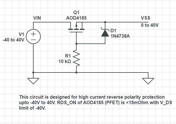
We used similar circuit as follows:
The reason for selection of AOD4185 is that its high current capacity, very low R_ds_on (~15mOhm), high V_ds limit in reverse (-40V) and cost effectiveness as it is largely used in TV LCD circuits.
The reason for using Zener diode D1 (of about 8~15V breakdown voltage) is the limit of V_gs of +-20V. But, we want to provide working range of 30V in evive. So this Zener diode will limit the voltage across the gate-source, while the resistor R1 will limit the current after zener breakdown.
[If someone want a smaller package of IC till absolute maximum of 30V range, than FDS6675bz (V_ds limit -30V) can also be used. We earlier tried with that, it was working ok for 40V foward bias and till -30V reverse bias. But on applying greater reverse voltage than -30V, the output started becoming negative as VSS ~= 30 - VIN, ie if we apply -36V than about -5V appeared. Hence we decided to use higher V_ds PFET]
The circuit is working absolutely fine and evive is now SAFE to reverse voltages till -40V :P
 Dhrupal R Shah
Discussions
Become a Hackaday.io Member
Create an account to leave a comment. Already have an account? Log In.