agp.cooper
-
New Motor Board Ready
08/28/2016 at 07:13 • 0 commentsNew Motor Board Ready
Not unexpected but it took 4 hours to assemble.
Powered up, one wire mistake found (a direct short between Vcc and Gnd).
The ESP-12E fired up and ran the installed blink program, voltages nominal and drawing 100 mA with motors disconnected (2.65 A with motors connected and energised).
Added a small heat sink to the 5v regulator as at 100 mA it will burn 700 mW. While okay without a heat sink it will get hot.
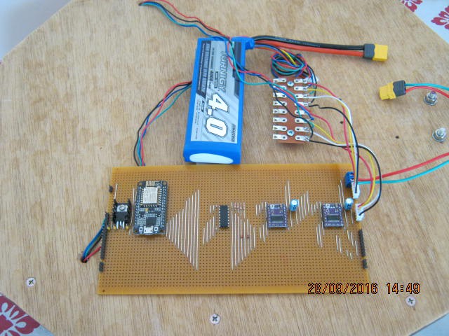
Here is the board connected to the testbed:
![]()
This board uses a PCF8574 (centre chip) to expand the IO. Both the DRV8825s and the ultrasonic sensors will be accessed via the PCF8574.
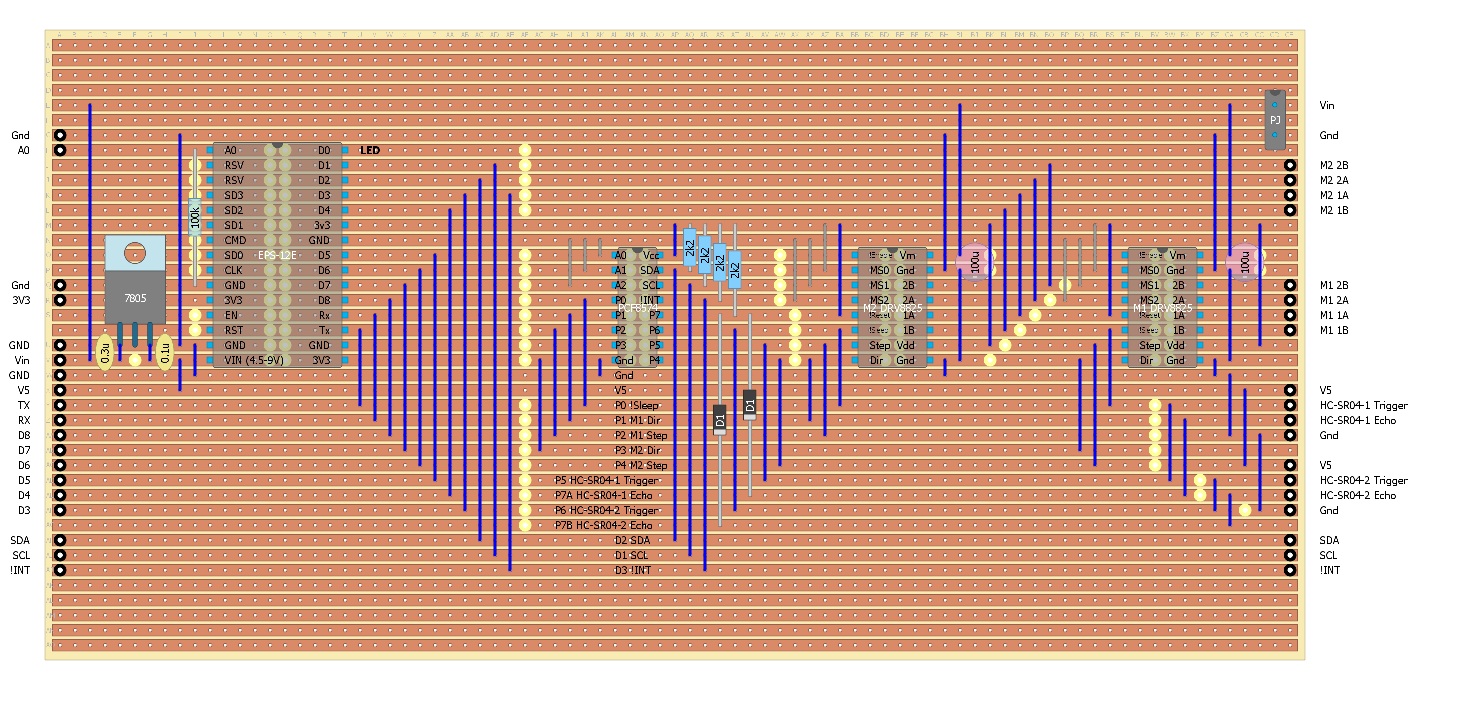
Here is the final strip-board design:
The next step is to rewrite the code to use the PCG8574 and Trigger library. Expect a couple of days.![]()
Software Updates
The basic I2C (Wire) is working, I can toggle the expanded port.
But I am having problems with the Serial code resetting the ESP-12E (the dreaded reset cycle) and my laptop!? If I slow the baud rate down to 9600 (from 115200) I get 30 seconds before my laptop resets. I did read something about this on the Internet with a fix but as usual cannot find the webpage again. The home made PulseIn() interrupt routine seems to be working as I get sensible numbers to my serial monitor before it blows up.
I tried no serial but with a variable period blinking LED (for the distance measurement) and it appears to work, but it still blow up if the sensor is too close or too far away from an object. So I would say it is ESP-12E.
So my options are to:
- Test the setup without Wire.
- Test setup With Wire, on an Arduino Uno.
- Find that ESP-12E Wire fix!
Results:
Loaded a example ASCII serial sketch and modified it to suit the ESP-12E:
On my desktop with a fresh Arduino IDE and USB driver:
- Worked on a Nano clone.
- Worked on an WeMos D1R1 (but had to remove the infinite loop at the end of the code and replace it with a blink else the "reset cycle").
- Worked on the ESP-12E (with the blink code).
On my laptop:
- Nano okay
- Wemos D1R1 okay
- ~5 seconds with the ESP-12E
Powering the ESP-12E with an external power supply:
- ~10 seconds with the ESP-12E
ARGH!!!!
Well I messed up my laptop trying to fix this. And this is not the first time I have messed up this laptop trying to fix USB problems. So now I need a RESET!
I needed a reset anyway because as fast as I make space available by moving my programs off the laptop it gets gobbled up somewhere else. I have one of those very cheap 32 GB SSD jobs (no hard disk). I guess I will have to put up with losing my Microsoft Office licence again! So this time I will take an image of the fresh install.
A day later, all done. All my programs reinstalled and 7 GB free.
The Nano worked and the WeMos D1 worked (I know I have to pre-install the CH340G driver).
The ESP-12E USB driver is not installed! Got it, the old CP2102 driver must have been bad, installed a new one and now it works properly.
I think its is time to take another disk image!
Last Night
Last night I got the sensors working with the PCF8574 chip. Realised the logic from the ultrasonic senors was inverted to what I originally thought. Inverted the PulseIn logic and now it works. But only with one sensor at a time. The diode NAND gate needs to be a diode OR gate. Okay, something for tomorrow morning.
Rebuilt the diode NAND Gate as an OR gate. A bit trickier than expected. You need to make sure that PCF8574 pins don't exceed their voltage ratings. Fired it up and fail. Time for the oscilloscope, checked the OR gates, works fine but the PCF8574 was generating some glitches(?) which were triggering the interrupt and freaking out the EPS-12E. The EPS-2E is nothing like an UNO, it is very sensitive about the code it runs and how the pins are hooked up. Everything I did to try and resolve the glitches made things worse!
Okay, rework the design for separate echo lines and push the DRV8825 !Sleep line off the PCF8574 and onto a real ESP-12E pin (I chose D8).
FAIL and FAIL and FAIL
It is now so bad I thought I had blown up the ESP-12E. It is pretty close to dead. Ordered two more ESP-12Es from ebay and then unsoldered the ESP-12E from the board. Plugged in a USB cable and it came immediately to life!? Okay check the board for shorts, nothing? Solder in some header pins to act as sockets for the ESP-12E, as soon as I plug it in, it dies. Check all the voltages, the only thing that looks suspect is the interrupt line.
Okay, unlinked the connections (wire links on the board) one at a time until it comes back to life. It was the connection between D8 and the DRV8825 !Sleep pins. Go figure.
Okay, Serial is working, the sensors are working. Now the D8 and DRV8825 problem.
Tracing the D8 and the DRV8825 !Sleep pin and checking the datasheet show that although the DRV8825 has a 1M ohm pull down resistor built in, the carrier has a 10k ohm resistor connected to the !Fault pin. Checking this pin I have linked it to the 3.3v power supply. This would make the !Sleep pin pull up. I have attached it to D8 that has a 12k ohm pull down resistor. Not good, especially for the EPS-12E. But why did I link the !Fault to the 3.3v power supply? On the A4988 this pin is Vdd and I lifted the design from the original motor board that used the A4988. So the solution is to unlink the !Fault pin from the 3.3v power supply.
Done and problem fixed, back to adding the motor controls and webpage.
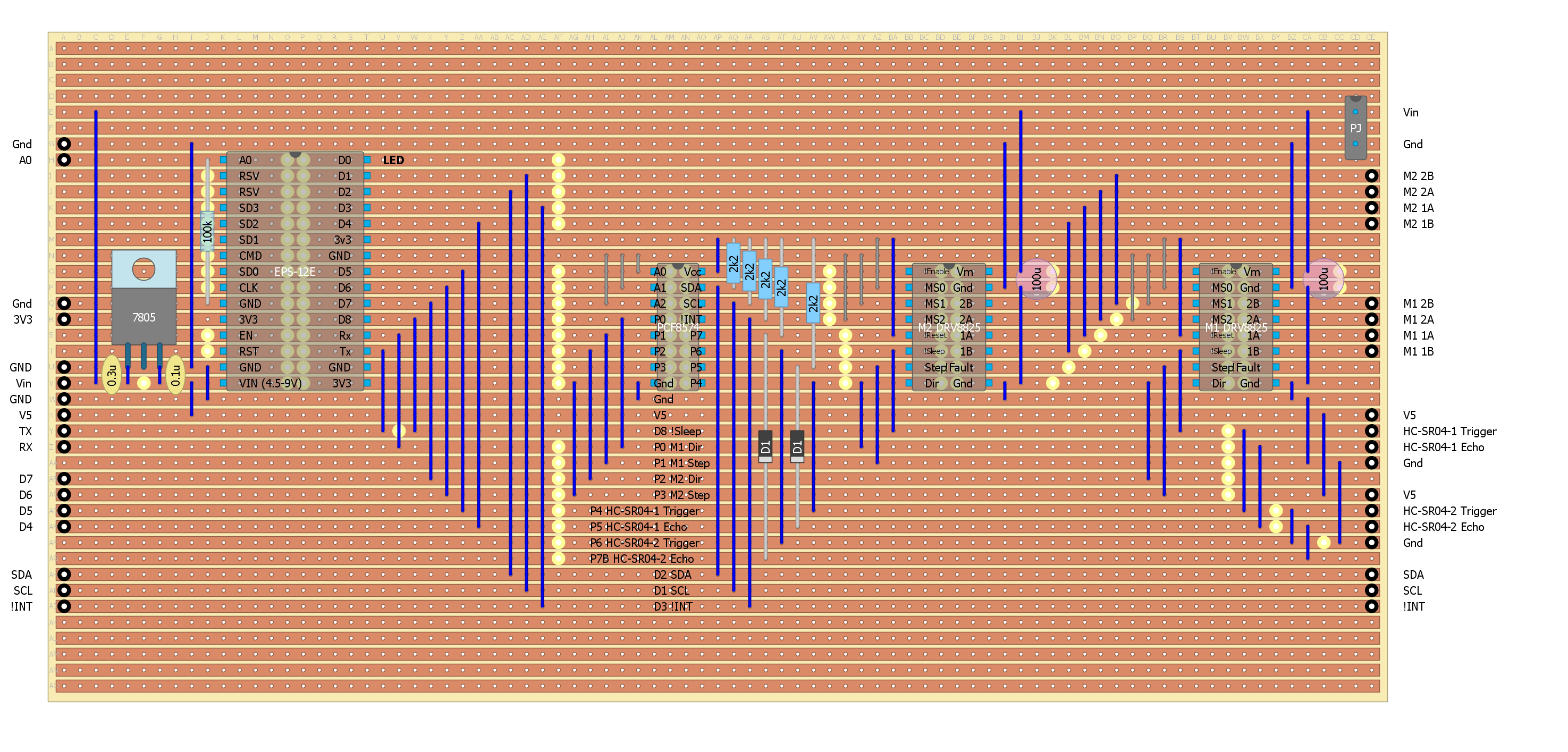
Here is the final Motor Board layout:
![]()
AlanX
-
New Motor Driver Board
08/26/2016 at 02:05 • 0 commentsStrip-Board Motor Driver
Knocked up a design on strip-board using a DOIT ESP-12E and a PCF8574 (and two DVR8825s):
![]()
(The above image should be re-scaled 32% for 1 to 1 printing.)
I am wondering about the SD* pins whether they can be used (I suspect they are used to access the flash memory?). Hard to find out but I suspect not (at least not easily).
I squished the two HC-SR04 echo lines onto P7 of the PCF8573 using a diode NAND gate. Had to make a 5v to 3.3v voltage translation anyway (the HC-SR04 is 5v). Added a 7805T between the Motor Supply Voltage and the EPS-12E voltage input to protect the ESP-12E from back-EMF (I am sure the 7805T can deal with the back-EMF better) and to power the HC-SR04s.
I read that the EPS-12E Arduino core does not support PulseIn() so I will roll my own using the PCF8574 interrupt line and the microsecond timer.
The EPS-12E SDA/SCL pins are programmable but I have used the defaults. So the pins are:
D3 I2C Interrupt (D0 is the built in LED)
D1 I2C SCL
D2 I2C SDA
The address of the PCF8575 is 0x20 (all the PCF8574 address lines are low).
I read the supported I2C clock frequency is up to 450 kHz so plenty fast for my application.
Need to let the "dust settle" on the design and double check before assembly (tomorrow?).\
AlanX
-
Fixed the Wheels
08/25/2016 at 08:17 • 0 commentsFixed the Wheels
I doubled up the adapter hubs (before):
![]()
And after:
![]()
This side required a card-board washer between the hubs but the other side was fine.
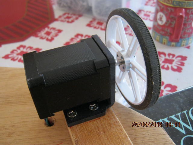
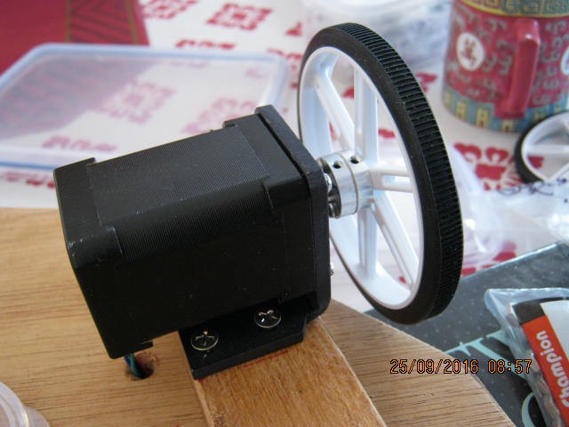
Test Drive
I took the testbed for a test drive. I am pretty impressed with these motors and wheels. They had no problem going over grass and rough surfaces.
Unfortunately they will not take the weight of the full size Dalek.
The WiFi range is about 20 m. I will have have to add an "out of range check" and shut the testbed when out of range.
I had another look at the hub adapters for the full-size Dalek and I think I am better off using these with a custom wheel (rather than the roller-blade wheels).
Software
Well "ticker" works with ESP-12E so I will rebuild the code to suit.
Hardware
I have also looked at using a PCF8574 (an 8 bit I2C port expander) to expand the available ports. That looks good too. But to use it I have to rebuild the hardware from the ground up. Basically add the PCF8574 to the ESP-12E first, then drive the DRV8825s off that. So it will be strip-board to get going and perhaps a PCB if I like it.
AlanX
-
Adding Ultrasonic Sensors
08/24/2016 at 09:36 • 0 commentsAdding Ultrasonic Sensors
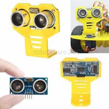
I thought it would be a good idea to add some ultrasonic senors to stop the Dalek from bumping into things, something like this:
![]()
Two problems:
- Some of the WiFi functions are the "blocking" type.
- I have only two digital pins and 1 analog pin left (excluding Rx and Tx).
So unless I rewrite the code to be timer/interrupt based (ticker perhaps?) then it would be a good idea to off-load the sensor processing to a slave MPU such as an ATTiny85. Actually if "ticker" works on the ESP8266 I should really be using that, I better have a look.
Port expansion is a problem because the SDA and SCL pins are in use! So I will need a software version of the SPI/\ or Wire library or similar it I go down that path.
Hooking Up the Ultrasonic Sensors
I bought some acrylic sensor mounts (now why every sensor mount type I have bought does not fit properly, I don't understand, but with a round file I made them fit). But I don't have any suitable mounting screws so it will have to wait until tomorrow.
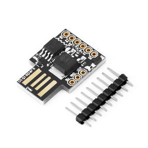
Although I have plenty of Digispark ATTiny85s how do I mount it (there are no mounting holes)?
![]()
Now I could just drill a mounting hole in the USB connection (after programming) or even after using a programmer for the Digispark (I have one). I can jump some power and the two digital lines off the CNC board.
The Digispark has Vcc/Gnd and 6 usable pins. So two to tell the WeMos to turn left or to turn right, and two (trigger and echo) for each ultrasonic sensor (two sensors: one left and one right).
So no need for a SPI or Wire library but things have a way of coming back (when I want to add something else)!
The CNC Shield
The CNC shield sounded like a good idea at the time but really I should have just used strip-board or even had a custom PCB made. The port expansion (SPI) could have been built-in. And I am going to need SPI for other functions that I want to implement later.
AlanX
-
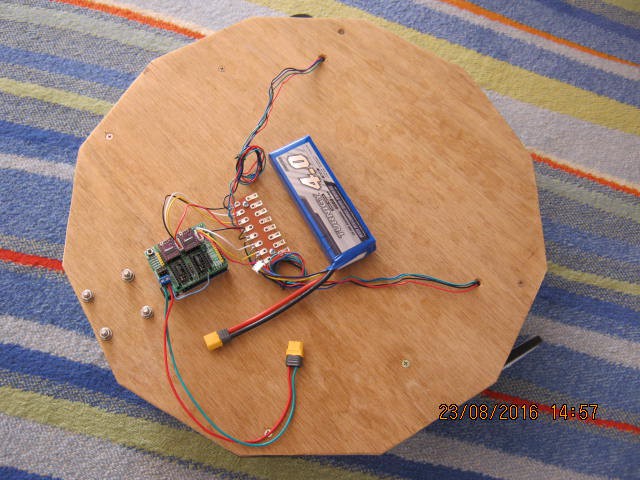
Power Up of Testbed
08/23/2016 at 07:12 • 0 commentsPower Up of Testbed
I mounted the components and wired them up. The battery is held in place with Velcro.
Needed to jump some power for the WeMos (note the short blue wire):
![]()
No Smoke
No smoke, nothing hot and supply voltage was nominal (always good).
Web page came up and the laser (sorry LED) responded to commands.
The motion control did not work properly but motors are engaged and it does step (so a software problem - no surprise).
Now if you are really sharp you will notice I have soldered the battery snaps the wrong way. It was such a pain soldering the heavy duty wire from the battery it is going to stay that way!
Fixed the motion control and cleaned up the code. Slowed the steppers down, speed up the webpage response time from 1 000 ms to 500 ms. Disabled the stepper when stopped to save power.
I need to check the DRV8825 current limiting settings.
Works okay, the 500 ms response time is about as fast as the webpage can update so precision turns are out. Probably should slow down turns further and speed up the forward movement.
A bit of a problem with the wheels coming loose and falling off! I will have to have a look at what can be done to fix it.
AlanX
-
Testbed for Motion Control
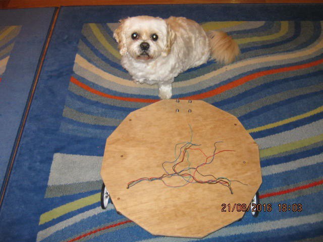
08/21/2016 at 10:21 • 0 commentsTestbed for Motion Control
The problems of working directly on the Dalek are:
- It is too big to bring inside (it does not fit through the normal door frame)
- It is a headache working on as everything is inside.
- The skate wheels don't have a lot of traction and the Dalek gets bogged.
- It drains the battery after about 30 minutes.
I really need to upgrade the wheels but that is another project in itself.
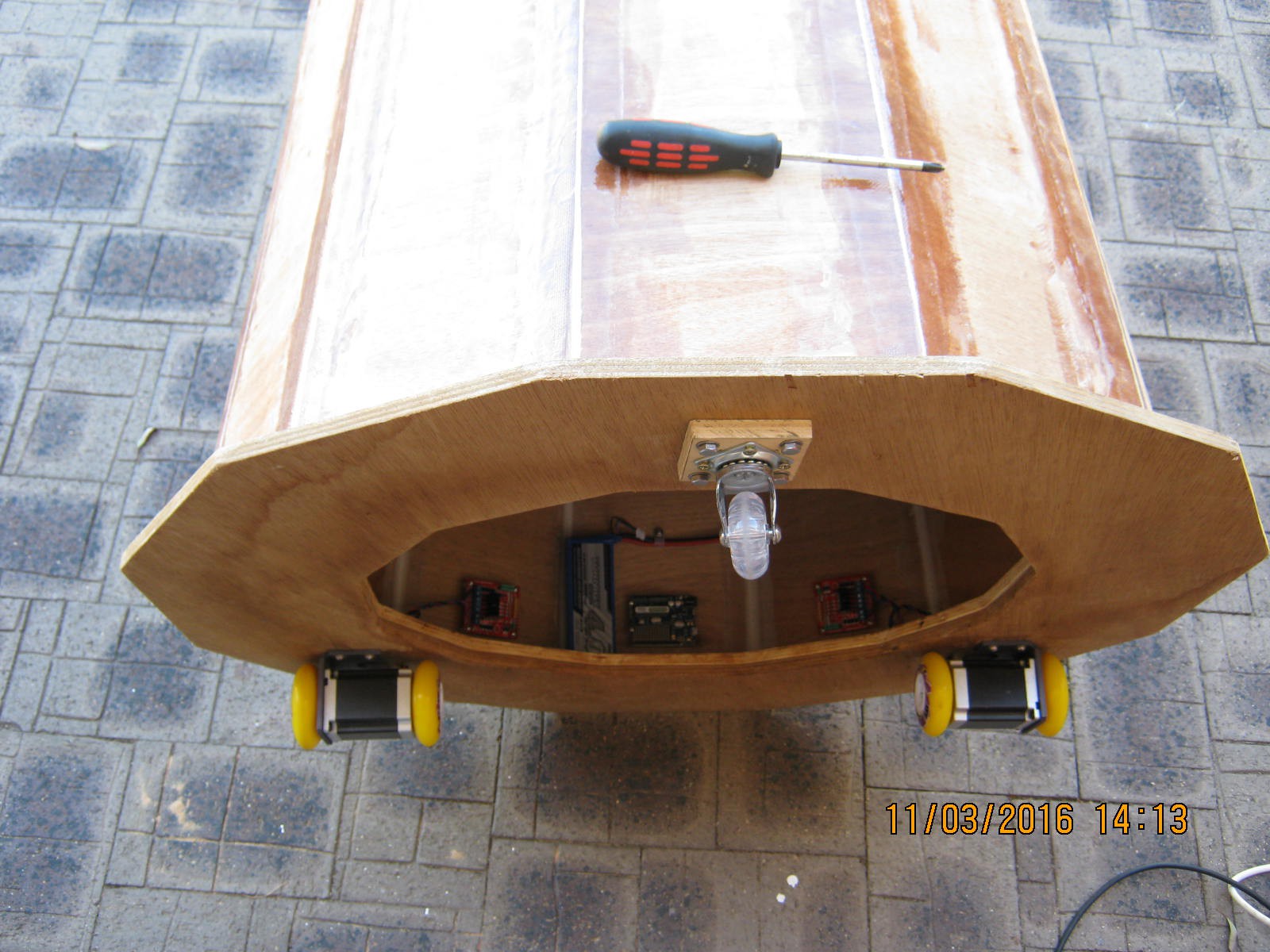
The solution is a testbed for the motion control (note the worried dog):
![]()
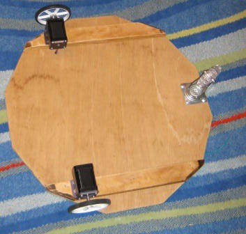
And the underside:
![]()
The steppers are 12v so no over current risk with the 12v power supply.
I would like to uses these components on the Dalek but the motor axles and wheels would probably bend or break.
So all I need to do now is mount the Arduino, motor controller and battery pack.
AlanX
-
The Replacement Driver Board
08/17/2016 at 11:16 • 0 commentsReplacement Driver Board
Rather than replace the dead components (all of them) I decided to move to WiFi.
I am also moving away from strip-board construction as PCB manufacture has become very affordable.
This time I will use a standard CNC stepper driver board (a clone of the Protoneer Arduino CNC shield) with the WeMOS D1R1 (an Arduino compatible ESP8266).
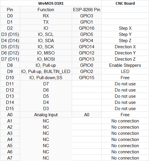
Here is the pin mapping:
I am using DRV8825 drivers but will limit the current to 1.5A. I will be using a 12 volt battery pack.![]()
Here is a pretty close approximation of what the WeMOS and stepper driver package will look like (image from the Protoneer ebay listing - Cheap at only US$20 but without the Arduino and the A4988s):
![]()
(source: http://i.ebayimg.com/images/g/5bsAAOSwUV9Wovve/s-l1600.jpg)
AlanX
-
In the beginning
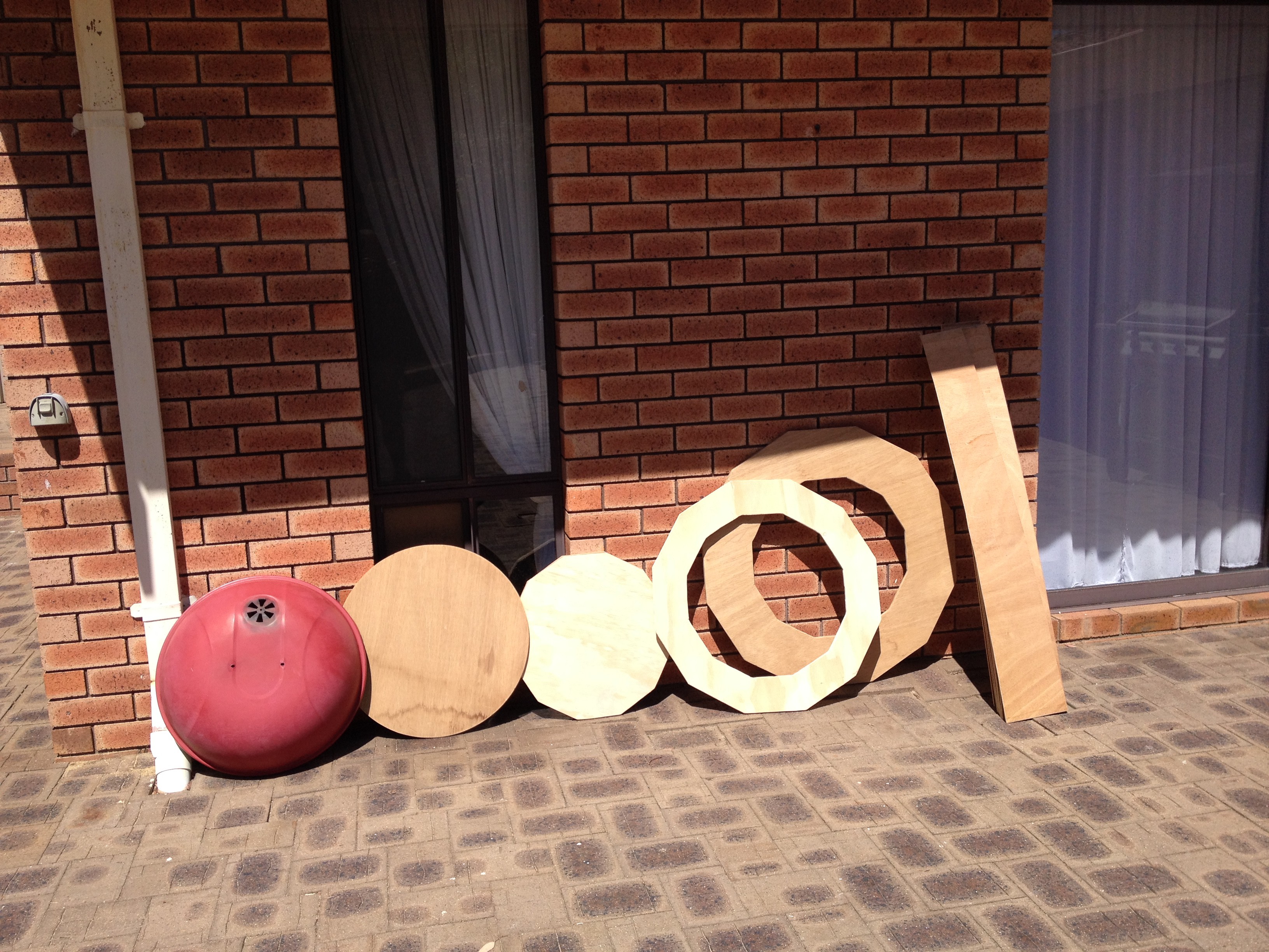
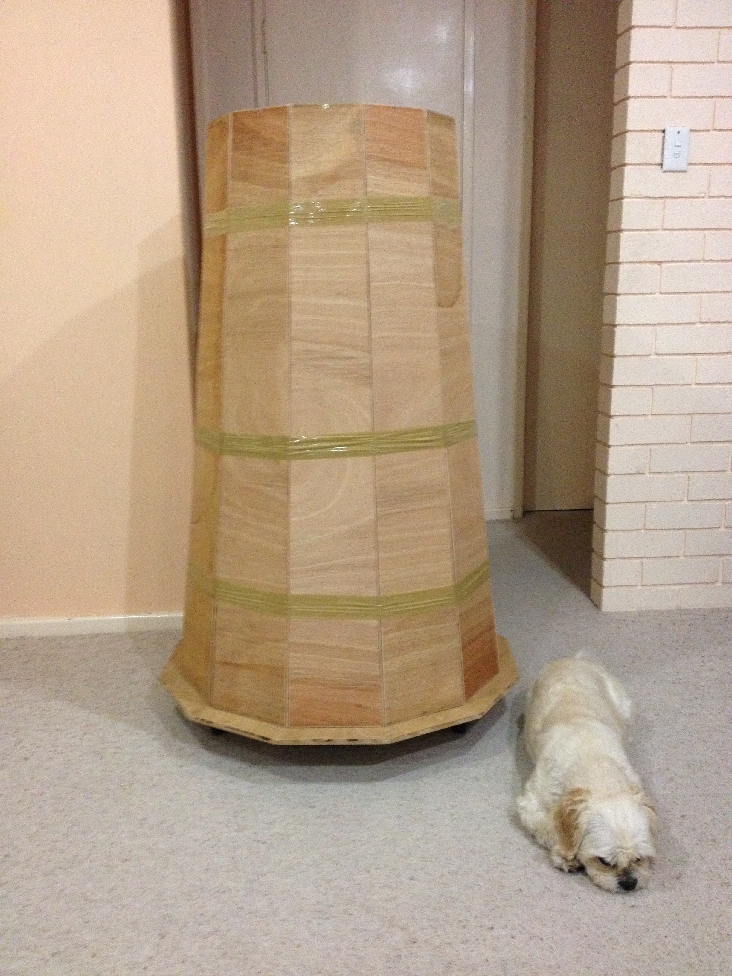
08/13/2016 at 15:39 • 0 commentsBuilding the Body
I had some plywood lying around going moldy and I found a barbecue lid during a council household waste throw out day, so I cut them up. Here they are ready for assembly:
![]()
Here it is taped together ready for glue (note that my dog has died of fright!):
![]()
Now you may have spotted why the Daleks always failed at taking over the universe?
Basically they are too wide to get through the door!
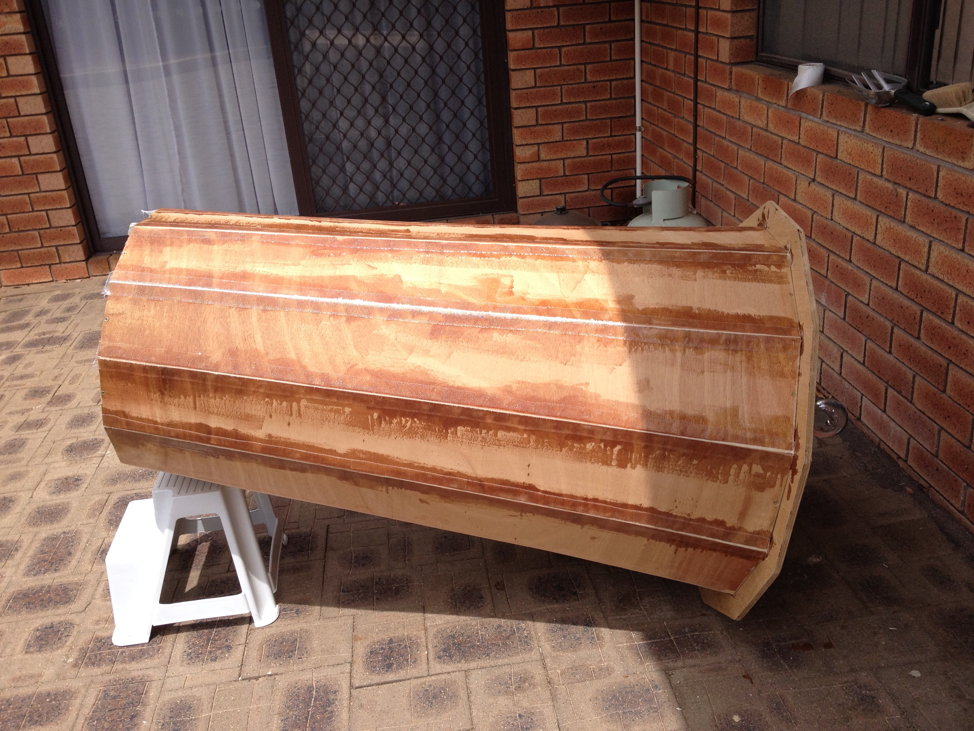
All glued together:
![]()
Here are the drive motors:
![]()
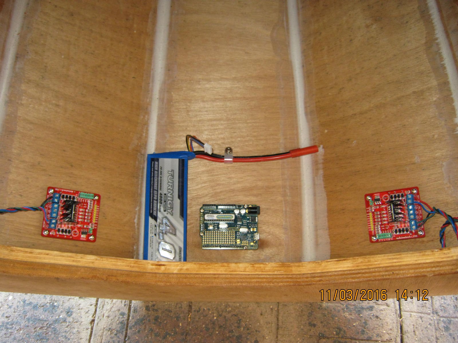
And the electronics:
![]()
These L298N drivers are a waste of time. I wrote a 20kHz PWM driver but the drivers are barely able handle 0.5A (way less than their specification). The heat sink is just too small.
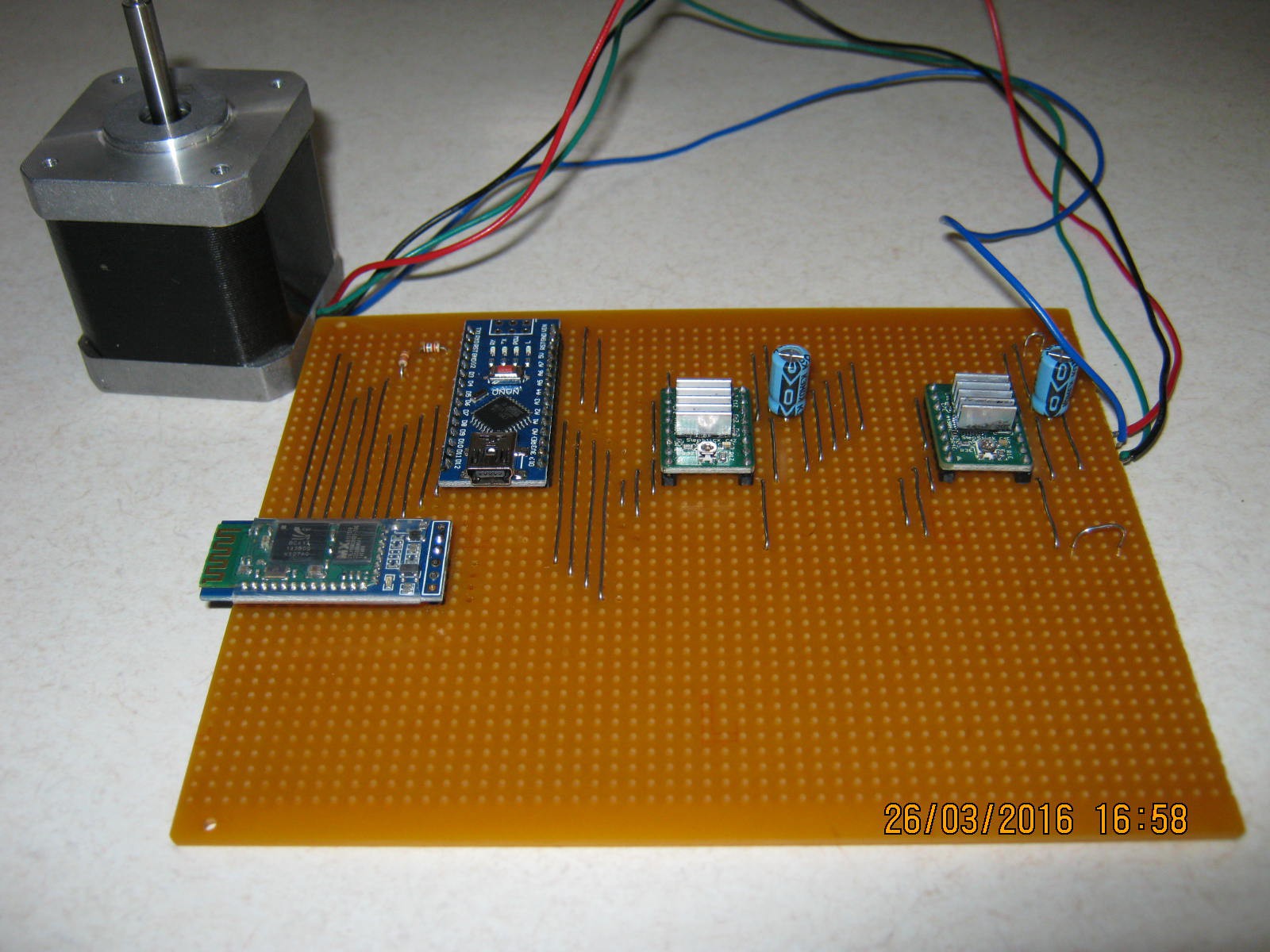
Here is a Bluetooth replacement using A4988s. Much better but Bluetooth is not reliable:
![]()
I blew all the electronic on this board when the battery lead accidentally touched something it should not have.
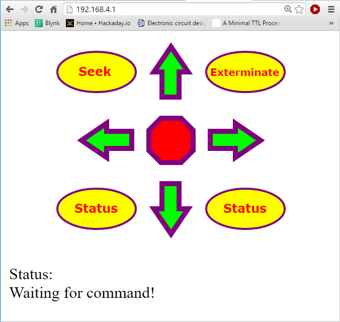
I can rebuild it but I have moved on to a an Arduino ESP8266. Here is the Dalek webpage:
![]()
This is neat as I can use my phone as a remote control.
The movement buttons are self-explanatory, the Status buttons currently reads the analog voltage and one of the digital pins. The Seek buttons returns a message that the Dalek is looking for humans to exterminate and the Exterminate button turns on the LED (lets pretend its a laser).
AlanX
My Dalek Build
For next Halloween I want a Dalek for "Trick or Exterminate"