agp.cooper
-
Master-Slave I2C
10/20/2016 at 03:33 • 0 commentsI2C Master-Slave using the DigiSpark
Start looking at master/slave arrangements using the ATTiny85 (as in the DigiSpark ATTiny85).
A have a couple of these lying around.
Found the TinyWire library.
I have some notes/code for using the timers so all good.
They are called "tiny" because after the Reset and SDA/SLC there are only 3 available pins.
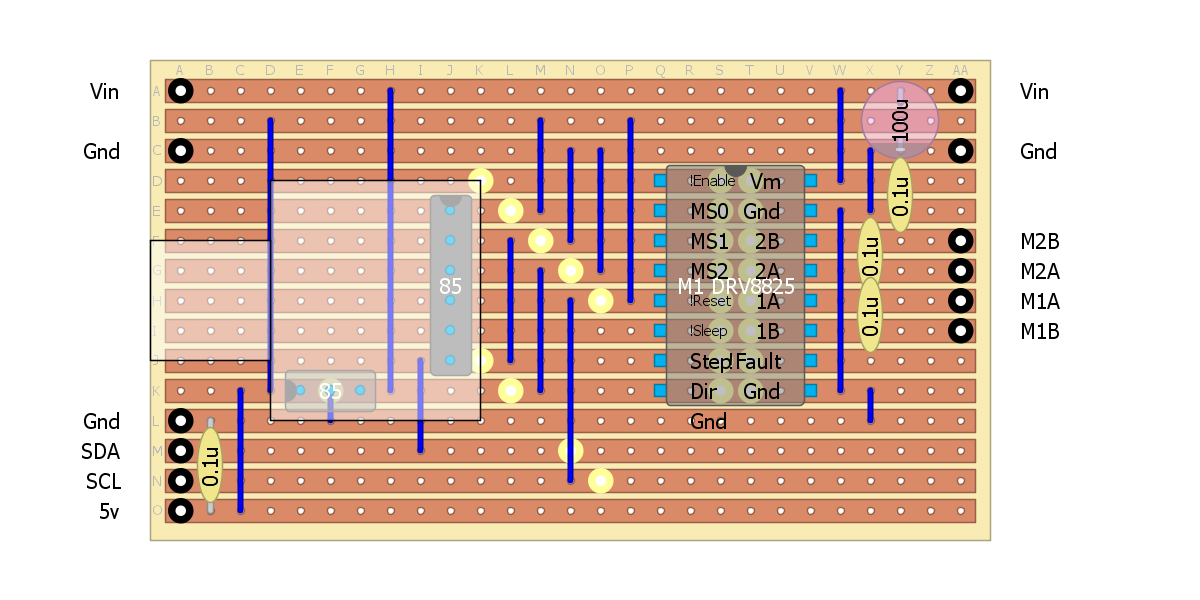
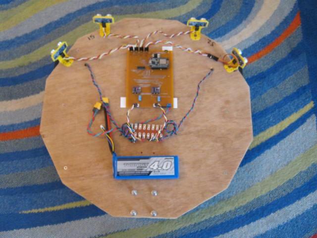
Here is the I2C stepper driver board:
![]()
The idea is to place each I2C stepper driver board next to the motor to avoid interference to the other electronics.
I have played with the DigiSpark serial interface but it is not stable.
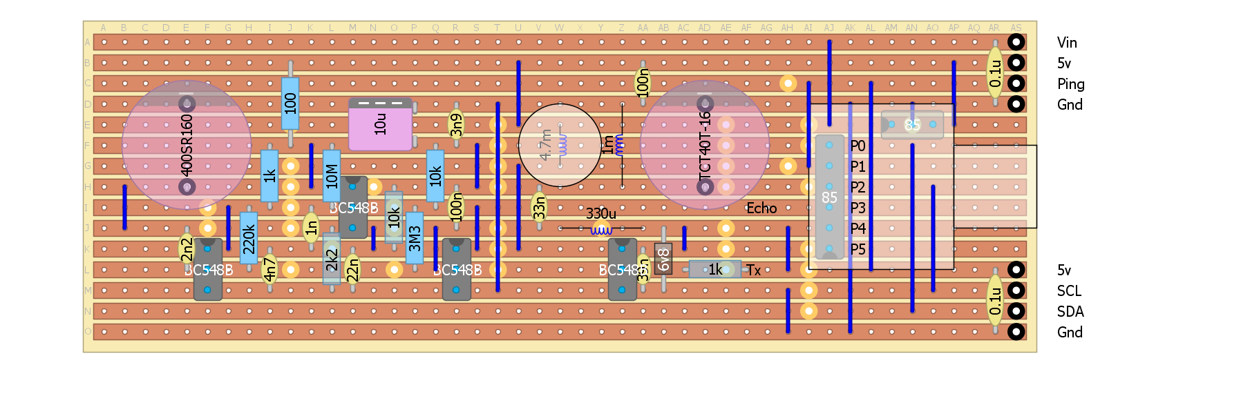
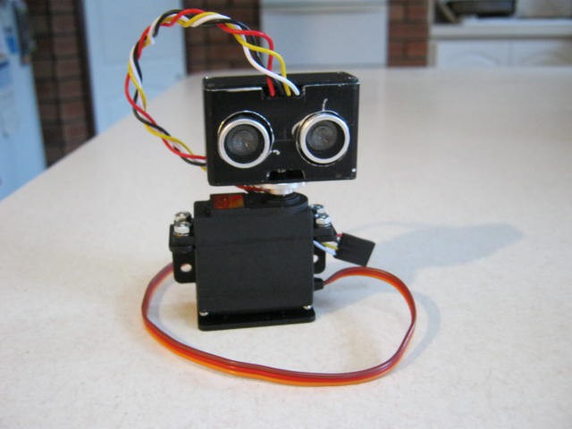
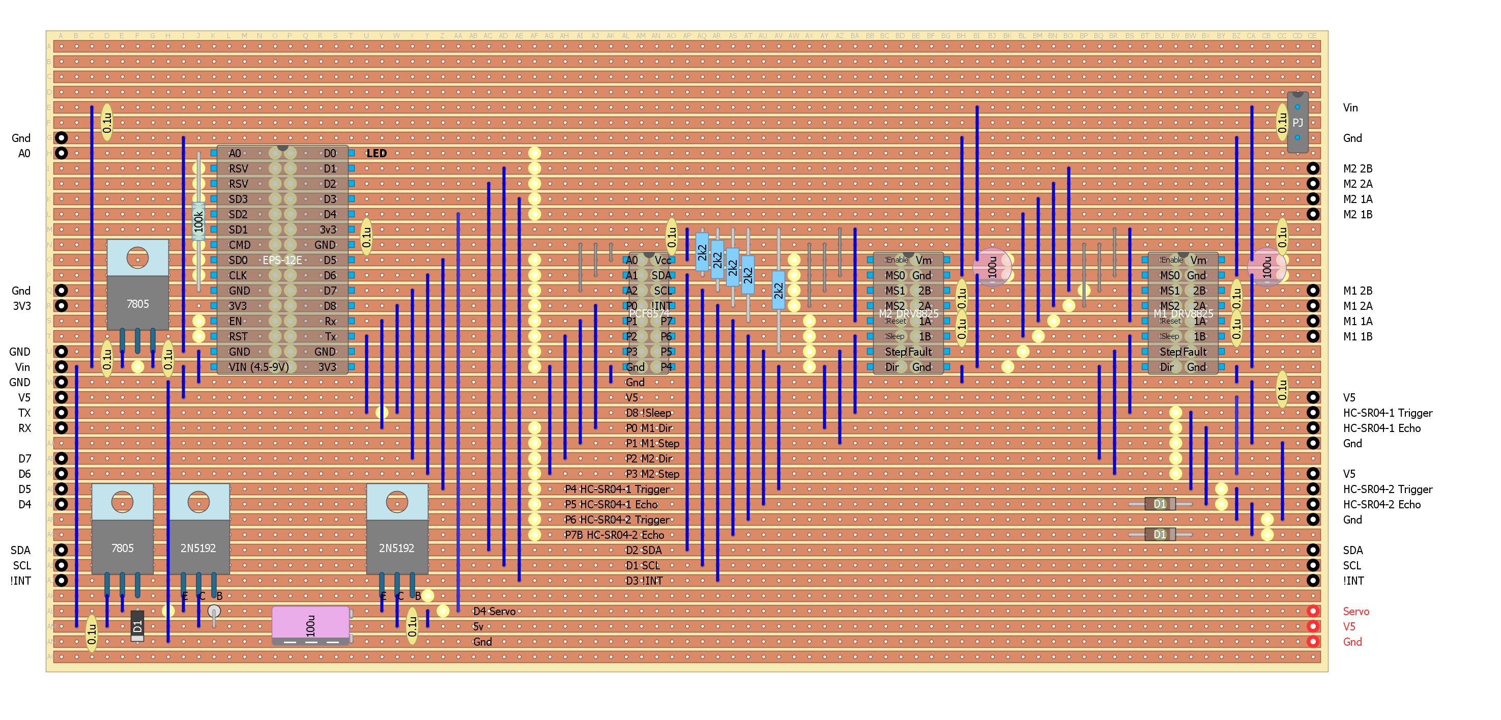
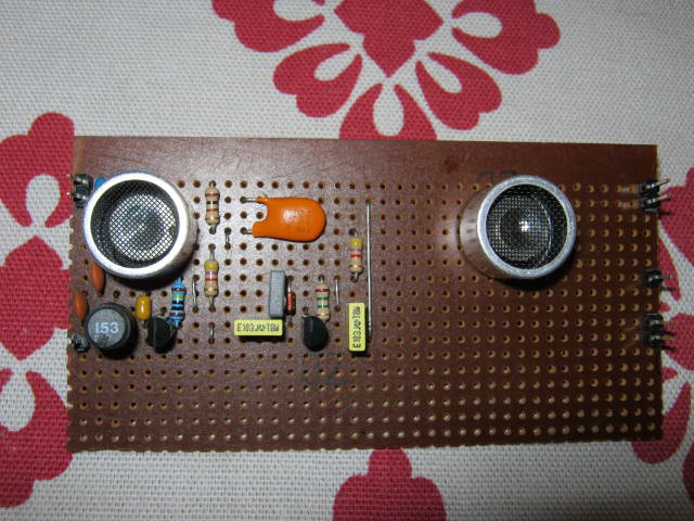
Here is the ultrasonic envelope detector transceiver board set up for I2C and Ping interface:
![]()
The above concept unfortunately will hear the 30 kHz stepper motor chopper frequency which I suspect was "the straw that broke the camel's back" that forced me to "surrender" (i.e. give up on making the Halloween deadline).
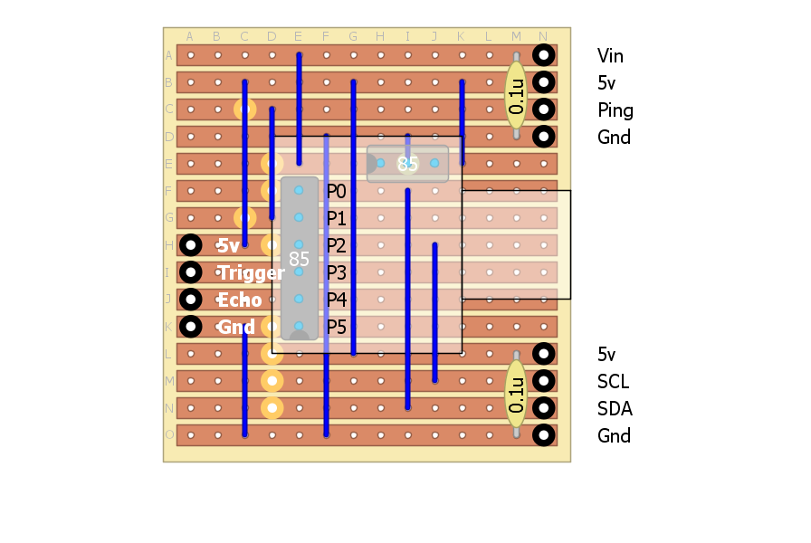
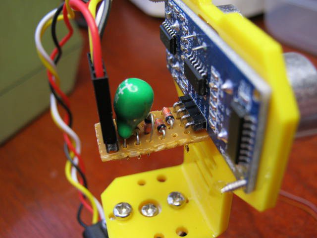
But really to begin should use HC-SR04 with a DigiSpark:
If I use a servo (with the common battery power) then I will need a custom power supply that can supply the peak current (~5A) and absorb back emf. A 5v6 1W zener and a 100uF capacitor across supply voltage works well in this case.![]()
The problem with the servo solution is that scanning is too slow given the HC-SR04 can take more than 200 ms to time out. At least the ATTiny85 can hurry up the time out.
I2S cabling
I will have to find some suitable shielded cable to link up all the modules.
30 kHz Stepper Chopper Frequency
I suspect that on of the issue I was experiencing in addition to Inductive kick-back (back EMF) and Inductive current coupling was the stepper PWM frequency noise up setting the HC-SR04. Although HC-SR04 uses an active filter it is probably not sufficient to filter out enough of the chopper noise.
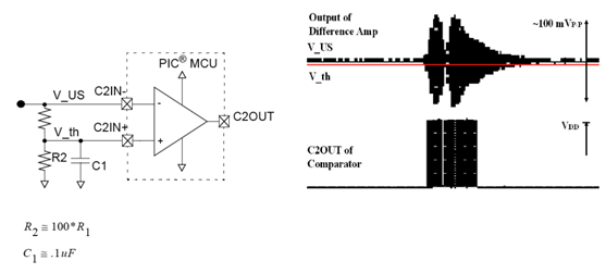
Checking schematics on the Internet of the HC-SR04 (that I have), the nearest match was (http://remotesmart.wikidot.com/esp202):
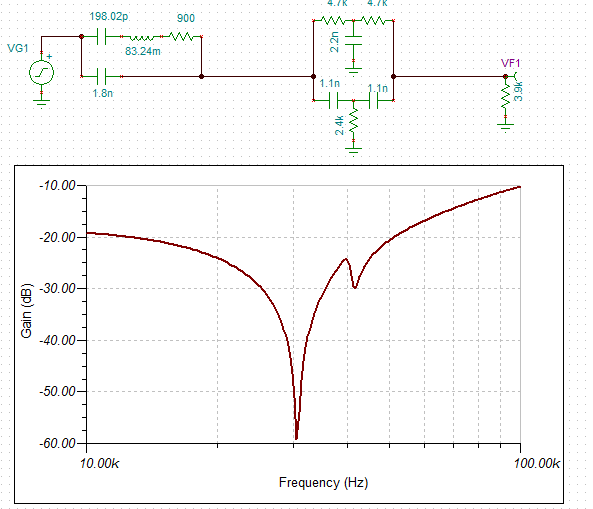
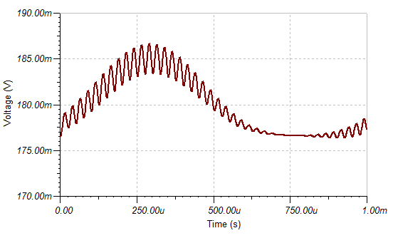
![]() Here is the response for the active filter (the IC2:C):
Here is the response for the active filter (the IC2:C):![]()
I can't read the capacitor values C2 and C3 so perhaps they are 500pF?
Others have confirmed the 20kHz centre frequency (http://uglyduck.ath.cx/ep/archive/2014/01/Making_a_better_HC_SR04_Echo_Locator.html) so I guess it is right.
The sensor itself offers little out of band rejection (if you accept the equivalent circuit):
The solution would seem to be a 30 kHz notch filter.![]()
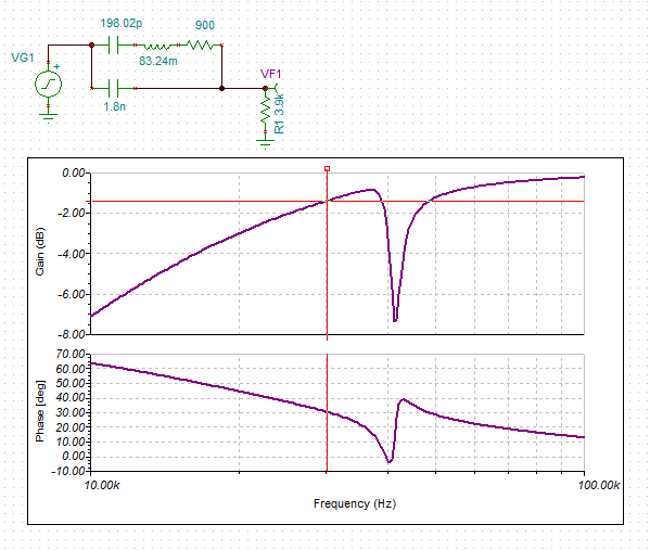
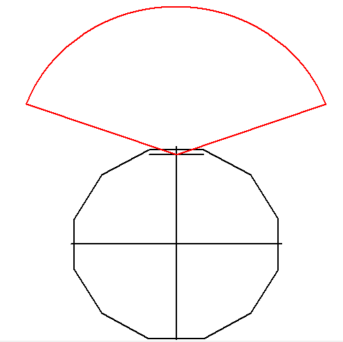
Here is the concept (rather than a design as the Q is too low):
This assumes that chopper frequency is reasonably constant (i.e. stays in the notch).![]()
Goertzel Again
As the ATTiny ADC runs at 125 kHz it makes a good candidate for a Goertzel tone decoder.
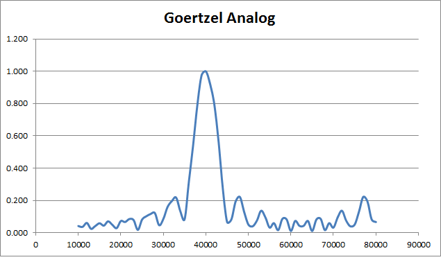
Using 125 kHz sampling frequency and 25 samples (measuring 8 pulses at 40 kHz) here is what the frequency response looks like:
![]()
The band-width is 5 kHz (=125 kHz/25).
The side lopes are only -13 dB down.
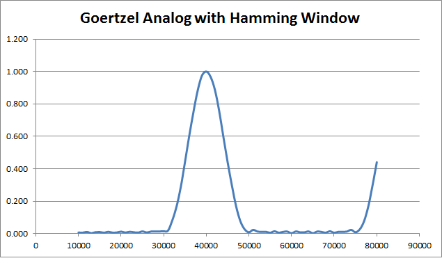
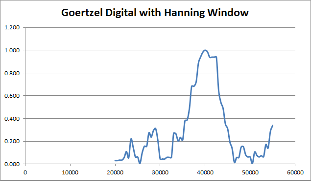
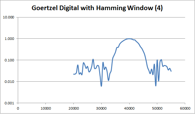
This can be improved by adding a "window" to the sample data (see http://www.mstarlabs.com/dsp/goertzel/goertzel.html) but at the cost of increasing the band-width:
Now that is an improvement!![]()
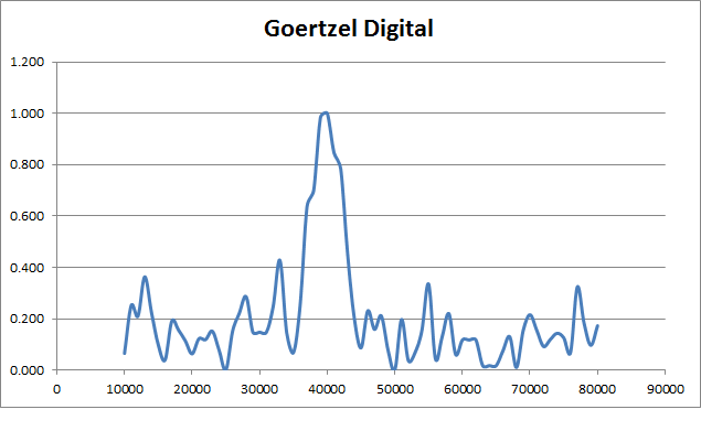
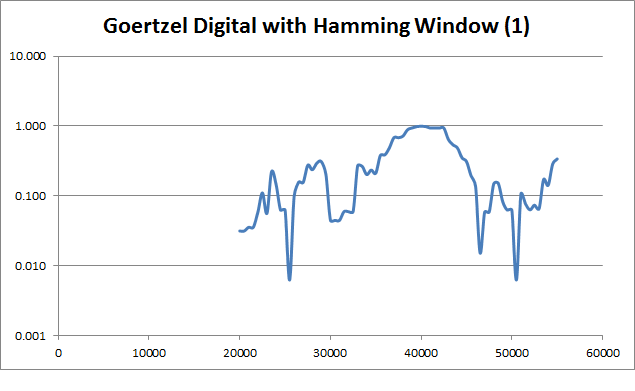
But does it work for pure digital data:
Yes but not great:![]()
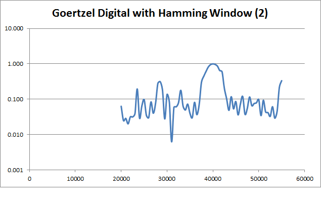
The notch at 30-33 kHz could be useful as it is around the stepper PWM frequency.![]()
Here is the same window but with a log scale:
How to improve?![]()
I tried using HP, Band Pass and Notch recursive IIR filters but with little success.
I am not sure why - could be coding errors or just not enough samples.
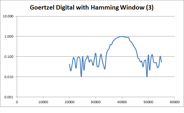
Here is the same setup but with twice the number of sample points (measuring 16 pulses):
No improvement on the noise floor but the band-width is half.![]()
Here is the same setup but with twice the number of sample points and twice the sample frequency (250 kHz, measuring 8 pulses):
![]() Okay the noise floor has fallen.
Okay the noise floor has fallen.And with 500 kHz sample frequency:
![]() And the noise floor as fallen again.
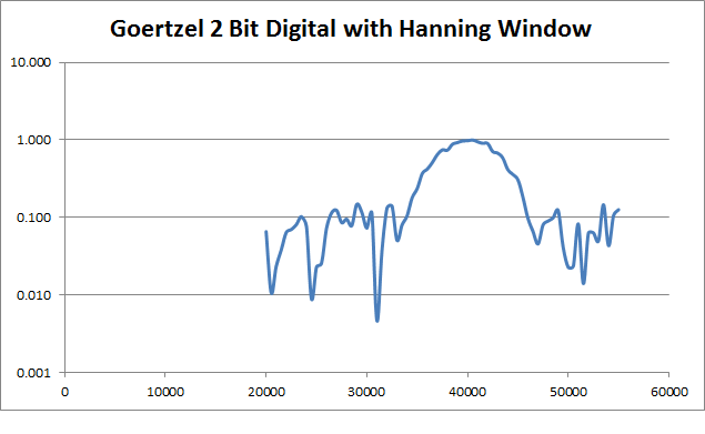
And the noise floor as fallen again.I even looked at a 2 bit binary (i.e. flash ADC) and that is approximately equal to doubling the sample frequency:
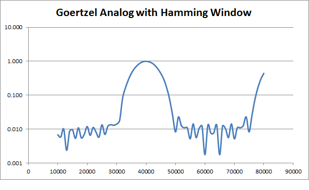
![]() Here is the original analog Goertzel using a log scale:
Here is the original analog Goertzel using a log scale:![]() So it would appear that either a very fast digital read (>1 Mhz) or the analog read (=125 kHz on the ATTiny85) can work.
So it would appear that either a very fast digital read (>1 Mhz) or the analog read (=125 kHz on the ATTiny85) can work.Rejection of the stepper motor 30 kHz PWM noise
The datasheet for the DRV8825 says 30 kHz (typical) but I need to measure it.
I also need to reduce the band-width a little, this means increasing the measurement period from 200 us (8 pulses) to say 250 us (10 pulse).
More if the PWM frequency is higher.
May also be worthwhile including a 30 kHz LC "trap" on the amplifier input.
AlanX
-
Surrender
10/18/2016 at 02:35 • 0 commentsI Surrender
I finished coding the motor/sonar board and tested the software.
I used serial print and the built in LED to indicate the sonar and command/motor status.
The sonar and motors work as expected separately but when combined too many false sonar triggers.
I am wondering if motor noise and/or vibration are triggering the sensors?
The ESP12-E is not that stable as well (it can stop working) suggesting electrical problems still exist.
Many months ago I had a remote control test bed that worked fine.
I have spent months trying to get the HC-SR04 working with the test-bed.
It seemed at the time adding sonar would be a small job.
What when wrong? I still don't understand!
Yes, the steppers somehow destroyed four HC-SR04s.
The servo certainly did take out two HC-SR04s and a 6.2v 1W zener (lucky it did not take out everything).
Learnings
Anything inductive needs special attention to the power supply, you have to consider inductive kick-back.
Better to build a separate motor controller and even a separate motor power supply.
Better to delegate software duties (i.e. use a master-slave setup) as managing everything on one MPU is difficult (particularly the ESP-12E).
Find a replacement for the HC-SR04!
I will return with a new plan of attack but after Halloween, AlanX
-
Electrical Interferance
10/14/2016 at 01:54 • 0 commentsElectrical Interference
I have made a serious error in this project trying to use a common power supply for the steppers and the other electronics.
A serious error that has cost weeks if not months of extra work!
Twisted pairs for the cables and decoupling capacitors on the stepper motor outputs seemed to fix the problems.
The problems appear to be two fold:
- Inductive currents coupled to signal lines.
- Inductive voltages on the power supply lines.
Inductive currents coupled to the signal lines
These upset the signal lines (i.e. inputs to the MPU) but I doubt they have enough power to destroy a device (i.e. eight HC-SR04).
Twisted pairs on the power/stepper/signal cables works wonders here.
The HC-SR04 has a 10k pull-up resistor on the trigger (input) and echo (output) which obviously helps (reduces sensitivity to inductive currents).
Reducing inductive currents
Previously, I added 100nF decoupling capacitors across the stepper motor terminals which reduced noise and very likely electrical noise (from the PWM).
My back of the envelope calculation was that the resonance frequency was 2.6 kHz.
Which is well above the operating speed (<=400Hz) and well below the PWM frequency (>>20kHz).
I found an application note for the designed of LC low pass filters for stepper motors.
Worth a review if it reduces the EMI further.
I don't think I am having any problems with inductive coupling any more but before the next set of tests I will run the steppers by themselves and check all the drive board power and signal lines.
Ran the tests, I only found some ripple on the battery line, everything else was clear.
Inductive voltages on the power supply lines
At last count I have "buried" eight HC-SR04s.
Probably killed the MAX232 as it a 5v device (6v absolute max).
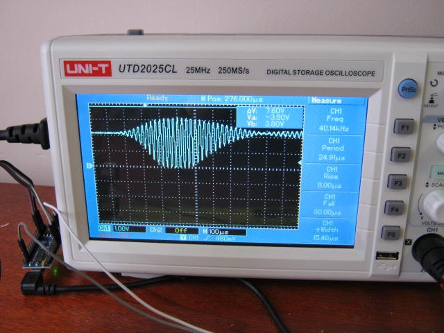
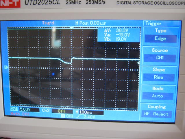
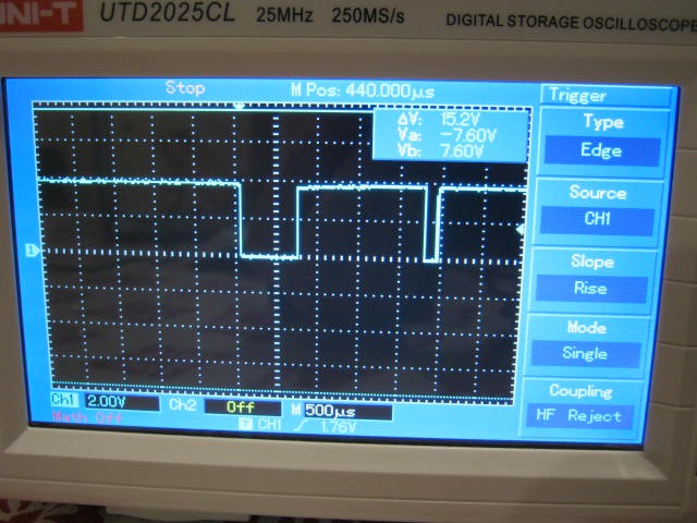
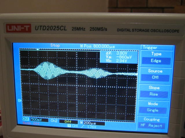
Certainly the servo killed the last two as they shared the same power supply (note the 13v inductive kick-back - limited by the 5v regulator diode back to the battery):
![]()
The inductive pulse is pretty high powered, at least 2 Ampere as the power supply (5v) has been pulled down to less than 3v (in the above inage).
The servo now has its own high current power supply and a 100uF capacitor to absorb the inductive spike (now less than 8v).
Reducing the output voltage to about 4.9 volts and adding a 5.1v 1W zener to the voltage regulator output reduces the inductive spike to "ripple".
Software Problems
Had some problems with servo sweep stuttering due to background processes interrupting the timer.
Here is a bad version where I try to lock the frequency:
#define servoPin D4
const int minAngle=15;
const int maxAngle=175;
int servoDir=5;
volatile int servoState=0;
volatile int servoAngle=90;
volatile unsigned long next;
void inline servoISR(void)
{
  if (servoState==0) {
    digitalWrite(servoPin,HIGH);
    servoState=1;
    next=next+40000+889*servoAngle;
  } else {
    digitalWrite(servoPin,LOW);
    servoState=0;
    next=next+1560000-889*servoAngle;
  }
  timer0_write(next);
}
Here is the fixed version where I let the frequency slip:
// Servo defines
#define servoPin D4
#define minAngle 15
#define maxAngle 175
volatile int servoDir=5;
volatile int servoAngle=95;
volatile unsigned long next;
volatile int servoState=0;
void inline servoISR(void) {
  next=ESP.getCycleCount()-180;
  if (servoState==0) {
    digitalWrite(servoPin,HIGH);
    servoState=1;
    next=next+40000+889*servoAngle;
  } else {
    digitalWrite(servoPin,LOW);
    servoState=0;
    next=next+1560000-889*servoAngle;
  }
  timer0_write(next);
}
It is not a perfect fix but the stuttering is gone.
The second issue was requirement to yield to background processes.
Any loop that is more than 50 ms must yield.
The yield() instruction can be replaced with a delay().
The optimum delay appears to be 2 ms (i.e. delay(2)) based on comments by other people.
HC-SR04 Time Out
The HC-SR04 datasheet states that the HC-SR04 time out is about 38 ms.But I am finding that after 40 ms the echo has not come (i.e. timed out).
Currently the software fires the next trigger pulse that triggers an echo about 300 us later (not good) but this is not consistent between sensors.
Increasing the timeout to 80 ms does not help.
Slowing the repetition rate down to 250 ms showed the HC-SR04 timing-out of about 185 ms (for two different HC-SR04s) to 200 ms (for another two different HC-SR04s).
So if I want to detect a timeout I will have to wait about 250 ms.
I checked and confirmed this long time out using Nano and the real pulseIn().
I have updated the code and it now works as expected (except for the 185 ms time out period).
Bug
Something I noticed was that I could not write out (Serial.println()) the value of pulseIn (which is a global volatile variable) inside the readSensors() procedure but it was okay in loop(). Procedure readSensors() is called by Ticker. Strange!
Next
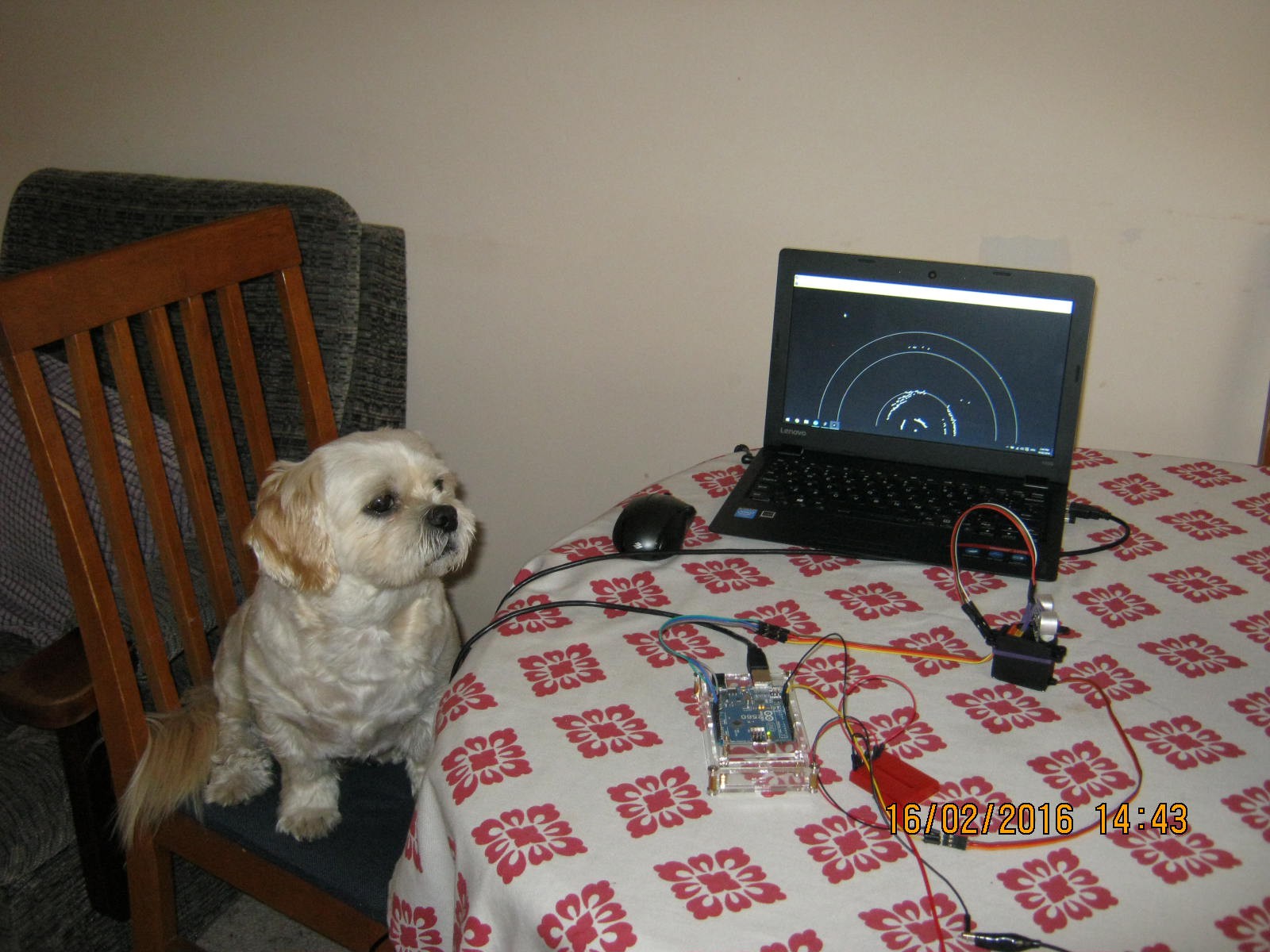
Next is to use the sensor return values to drive the stepper motors.
Here is the new setup:
Here is the sensor with the protective board:![]()
![]()
AlanX
-
Scanning Sonar
10/04/2016 at 10:52 • 0 commentscanning Sonar
Not a good day!
The old scanning sonar files are lost.
Okay start from scratch:
- Make a sonar scanner - done.
- Get a servo scanner working (took an hour or so to realise I forgot the common ground) - done.
- Get the HC-SR04 working - fail!
- Get a processing sketch to display the results - todo.
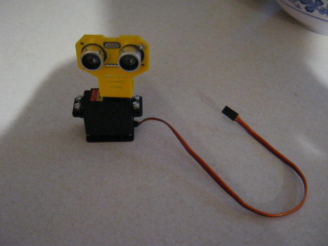
Here is the sonar scanner:
![]()
Could not get the sensor to work!
I had no problem a few days ago?
Tried three of them.
They would work if I touched them and then stop (you can hear them fire) when I move my hand away.
Changed to an Arduino Uno rather than a nano - same problem.
Use a power supply for the Uno.
All the sensor behave the same - cannot work it out.
Have I blown them up (my laptop USB has 35v AC on it - modern power supplies are all like this - unearthed)?
I will have to check if the trigger pulse is getting through with the oscilloscope (tomorrow).
Tomorrow is here
Relocated to my old desktop (it is earthed and less AC voltages on the metal surfaces).
Compiled NewPing and my version of sonar code.
Well the same problem (but not as bad).
The problem is the HC-SR04 stops working and usually (not always) needs to be powered down to reset.
The HC-SR04 fails if pointed into space (i.e. timeout) but can fail in other ways.
I have test three sensors and they all fail.
Fails for 50 ms and 1000 ms between triggers.
Checking with the oscilloscope, the trigger pulse for both the NewPing and my code is fine.
(The NewPing pulse threw me at first until I realised it was a trigger/echo signal.)
Added a 100uF to the Vcc and Gnd pins - no change - There was no real noise on the power supply or signal pins anyway (when using the desktop).
How does it fail? The Echo locks high!
There are schematics on the Internet that show the outputs are pulled high by a 10k resistor and controlled by a uP.
Emil's Projects (http://uglyduck.ath.cx/ep/archive/2014/01/Making_a_better_HC_SR04_Echo_Locator.html) has a pretty good description of the SHC-SR04.
Still I am puzzled? I did not have this out right failure when before.
It is as if they were damaged by the Dalek Test-Bed?
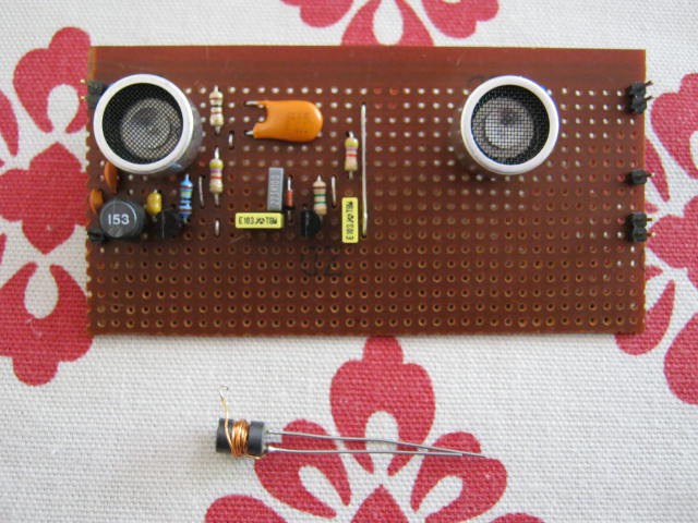
I only have one virgin sensor (that hs never been used on the Dalek Test-Bed) that I used for the twin sensor experiment (fail):
![]()
So I tested both (I left provision for this) and one sensor does not work but the other does.
I wonder which one has never been used on the Dalek Test-Bed!
The death statistics are five HC-SR04s, all from the Dalek Test-Bed!
Plausible Theory
Well it seems plausible that the Dalek Test-Bed (with the stepper motors) has damaged the HC-SR04s.
So high voltage inductive currents could be the reason(?).
But how? The HC-SR04s are feed from a 5v voltage regulator and each are decoupled with a 100n capacitor at the jumper.
The leads although twisted do pick up noise as a HC-SR04 with an extension (far right hand side) did not work (until the extension was removed):
![]()
How to fix?
I wish I knew what has failed on the HC-SR04?
I think I have taken enough precautions for the power supply (because it is an obvious problem area).
But I have not done much for the HC-SR04 inputs and outputs (a possible failure mode is from inductive currents?):
- A resistor (2.2k?) in series with the input and outputs to limit the MPU protection diode currents.
- Shield the HC-SR04 in a metal box.
- Use shielded the cables.
Just as well I order 10 more HC-SR04s.
Scanning Sonar
Scanning sonar up and running.
Usual problem of occassional zeros etc. but nothing like problems I have been having with the fixed sensors.
Emil's Projects (http://uglyduck.ath.cx/ep/archive/2014/01/Making_a_better_HC_SR04_Echo_Locator.html) suggests if is just crappy programming of the MPU.
So now I need some flexible shielded cable, a couple of current limit resistors and a metal box to mount the HC-SR04.
Here it is:
![]()
Pretty rough job but no time for perfection.
Inside the box is a strip-board with a protective circuity that should protect the HC-SR04 from any stray inductive currents.
I suppose I could stick a face on it.
Another Envelope Detector
My first (two transistor) receiver was a bit of a flop.
Basically the first transistor was upsetting the bias of the second transistor.
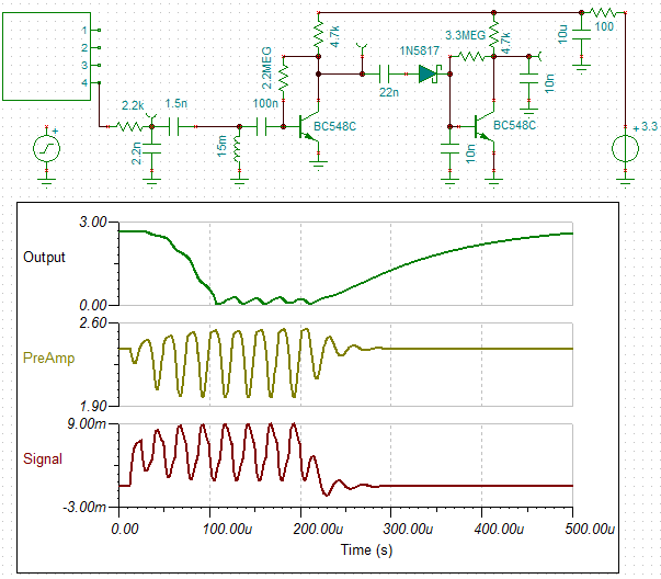
Here is another attempt but using a transistor detector instead of a schottky diode:
![]()
This time the second transistor is biased very low (just like a Class B amplifier).
The transistor output (no signal) is just 80 mv.
The gain (loss) at this operating point is very non-linear.
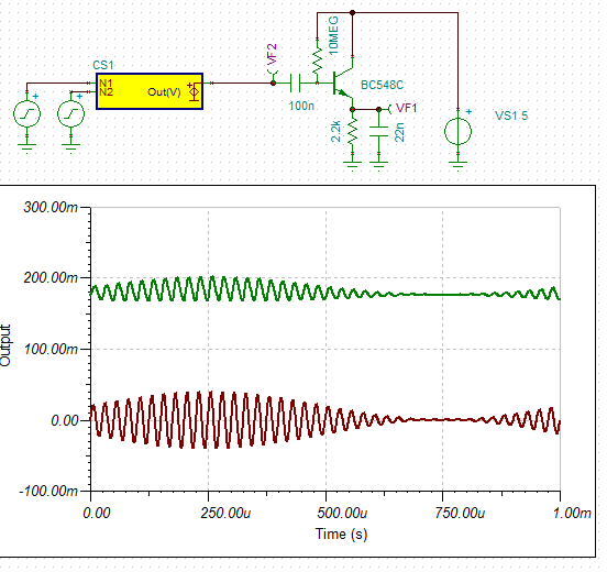
Here is the detector by itself (red input and green output):
![]()
Adding a second low pass filter to the output brings out the detected modulation.
![]()
Sonar Scanner Software
I have some "PulseIn" code that will work with the PCF8574.
I just need to write the servo code.
The range required is less than 40 cm (note that the servo cannot scan 180 degrees):
The scan width (above) is about 75cm and a typical door is 80cm (clear), therefore range detect should be reduced to about 35cm.![]()
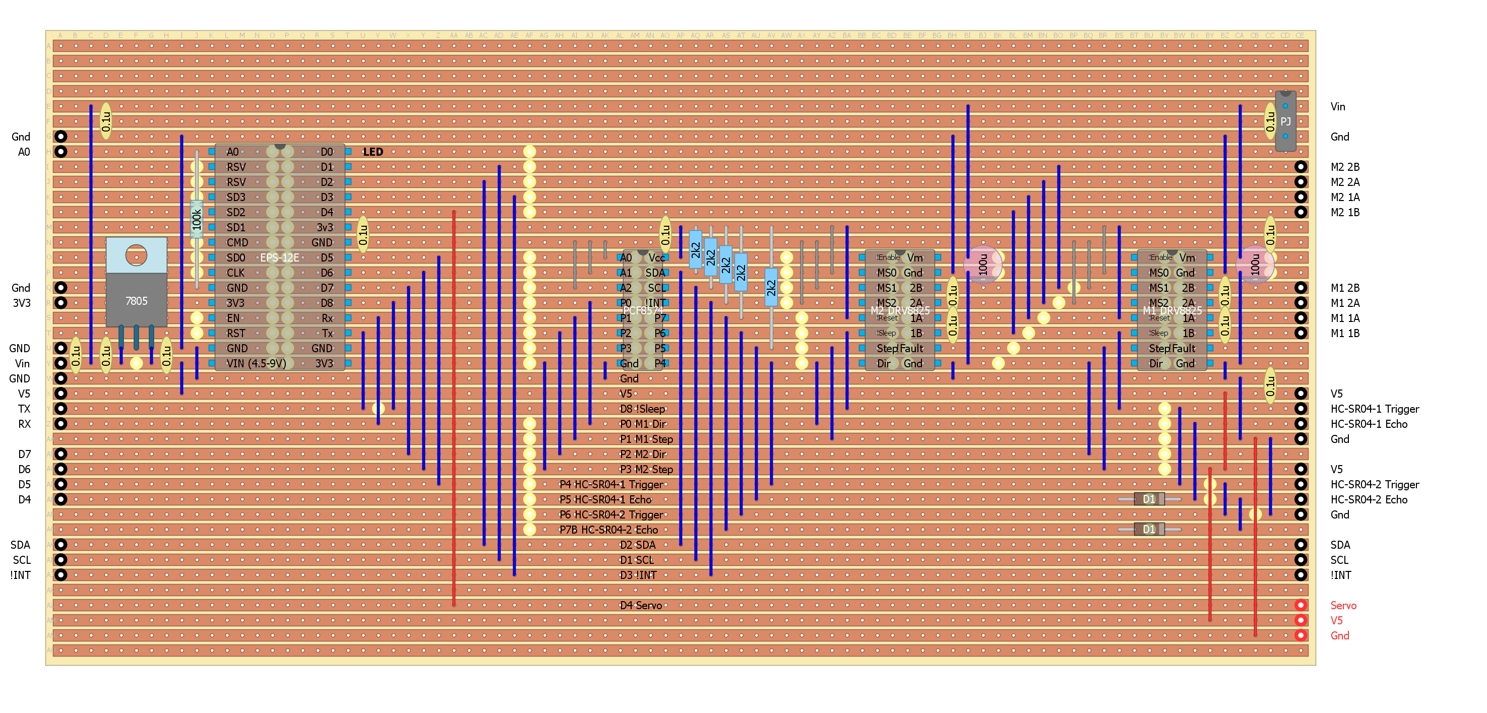
Updated Driver Board
Reworked the second last driver board for a servo output (red):
![]()
Bricked my last two HC-SR04s
I brick my last two HC-SR04 sensors.
Now I am shot (until the new ones arrive, a week away).
How did I do it?
This time I cannot blame inductive currents.
The sensor were working with the driver board until I added the servo motor.
Checking the driver board I found a 13v spike on the 5v side of the 5v regulator:
![]()
Well that would be enough to take out the HC-SR04s (lucky it did not take out anything else).
There is 0.2 uF on the 5v side of the regulator, so I am surprised.
At least I know that it was over voltage that killed the the HC-SR04s.
The answer is a 6.8v zener diode across the Vcc and Gnd pins.
I added 100uF and it is still very disturbing:
![]()
It is pulling down the 5v supply to 2.5v for 1 ms!
Checking the Internet it seems that standard servos will pull about 5 A peak.
A 7805T will peak at 2.2A so no wonder that the 5v line was pulled down.
Here is a simple 5v regulated circuit that can sink more current:
![]() Here is the updated driver board (with a separate power supply for the servo:
Here is the updated driver board (with a separate power supply for the servo:![]()
I think it may have been easier to use a stepper rather than a servo.
Partial Success
Added the servo regulator, works fine.
The problem now is that the servo sends an inductive voltage spike back to the transistors (I used two paralleled 2n5192).
As the transistors are rated at 80 volts that is pretty well what I was getting (I did not try and measure!) on the oscilloscope.
I added a 1W 6.2v zerer across servo power supply with no success(?)
I added a 1N4007 back to the battery and yes that limits the pulse to 13v and as this is a dedicated supply for the servos that should be okay.
Added a 100uF across the servo power supply, I now have a a long period (~30 ms) 8v peak.
Removed the zener - no change.
Good enough - move on:
![]()
Servo Signal
The ESP-12E does have a servo library but working that with a HC-SR04 DIY "PulseIn()" via a PCF8574 is a bit problematic.
The servo signal on the oscilloscope misses lots of pulses.
Even the stand alone sweep sketch suffers these problems.
Part of my problems were due to:
- Avoiding the use of the EPS-12E timer (as there is little documentation).
- Using the PCF8574 instead of multiple slave processors (i.e. ATTiny85).
The ESP8266 servo library seems to use polling as delay() kills it.
I decided to have a look at the ESP Timer system, there are a couple of worked examples on the Internet.
Here is my version (of sweep), pretty simple really:
#define servoPin D4
volatile int servoPulse=0;
volatile int servoAngle=90;
volatile unsigned long next;
void inline servoISR(void){
  if (servoPulse==0) {
    next=next+40000+889*servoAngle;
  } else {
    next=next+1560000-889*servoAngle;
  }
  timer0_write(next);
  servoPulse=1-servoPulse;
  digitalWrite(servoPin,servoPulse);
}

void setup()
{
  // Servo initialisation (uses D4)
  pinMode(servoPin,OUTPUT);
  noInterrupts();
  timer0_isr_init();
  timer0_attachInterrupt(servoISR);
  next=ESP.getCycleCount()+1000;
  timer0_write(next);
  interrupts();
  // Serial.begin(9600);
  // Serial.println();
}

void loop()
{
  const int minAngle=16;
  const int maxAngle=176;
  const int midAngle=96;
  static int servoDir=1;

  delay(50);
  // Next position
  if (servoAngle>maxAngle) servoAngle=maxAngle;
  if (servoAngle<minAngle) servoAngle=minAngle;
  if (servoAngle==maxAngle) servoDir=-servoDir;
  if (servoAngle==minAngle) servoDir=-servoDir;
  servoAngle+=servoDir;
  // Serial.println(servoAngle);
}
The new HC-SR04s have arrived
I hooked up the orignal version of the scanning sonar:
![]() Had a play with the servo pulse constants (further refinement still required):
Had a play with the servo pulse constants (further refinement still required):if (servoPulse==0) { next=next+40000+889*servoAngle; } else { next=next+1560000-889*servoAngle; }The Internet has a lot of incorrect numbers for servos.
The range for this servo (0 to 180 degrees) is 0.5 ms to 2.5 ms.
Protecting the HC-SR04
I seems reasonable that over voltage on the HC-SR04 power supply is what killed it.
I think probably kills the voltage multiplier (i.e the ST232CD?).
For the servo, a 100uF power supply capacitor tamed the inductive voltage spike.
So this is the way I will go (I was disappointed with the performance of the 1W 6.2v zener - probably a 5A peak current was a bit of an ask!).
Here is the proposed HC-SR04 protection board:
![]()
I will solder it to the base of the HC-SR04.
Zener Diode
I was not real happy with the zener not working.
So as a test I put a 5.1v 1W zener across the servo power supply.
Worked fantasic!
Checked the zener voltage (5.03v) and current (10mA), so great.
Just to be sure I swapped the 7805 voltage reference diode (1n4148) with a schottky diode (bat41).
The regulator voltage is now 4.93v so all should be good for the servo power supply.
Added a 6v8 400mW zener (all I had) across the power supply of the HC-SR04 protection board.
AlanX
-
Testing the transmitter and LM567 receiver
10/03/2016 at 13:47 • 0 commentsTime is running out
Time is running out!
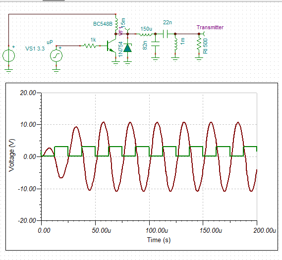
Before I walk away from DIY ultrasonic sensors I thought I better test the transmitter and LM567 tone decoder receiver.
![]()
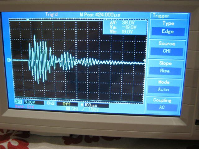
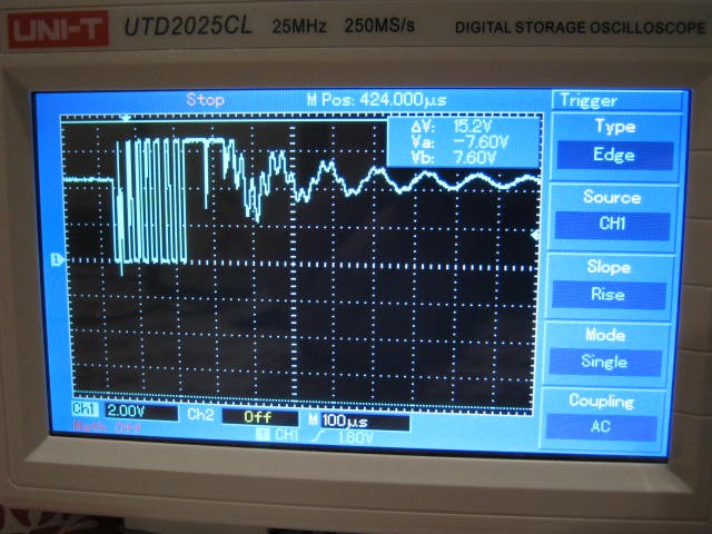
Here is the transmit pulse on the transistor collector:
![]()
Pretty untidy! Something is going on as the base pulses are clean?
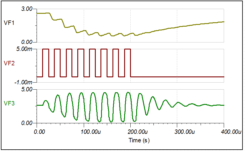
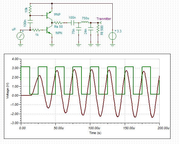
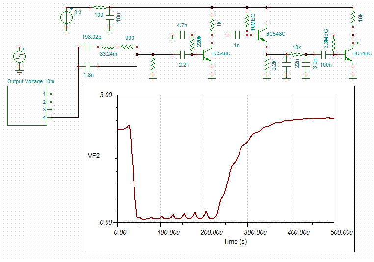
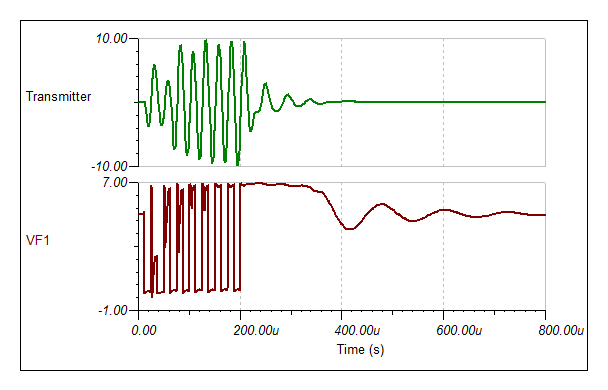
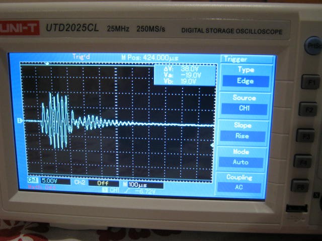
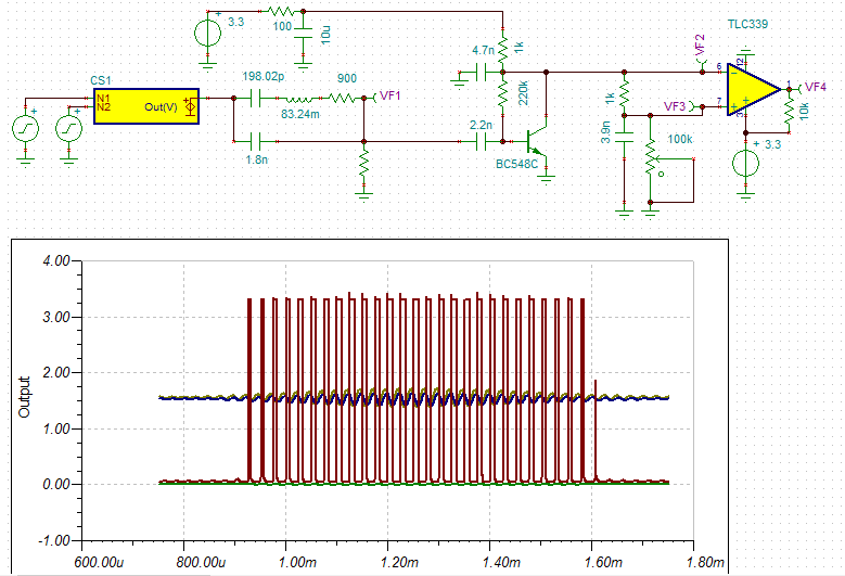
Here is a transient simulation to an 8 pulse sequence:
![]()
So it is working properly!
The ringing during the pulses is part of the network matching behavour.
The post pulse ringing (after 300 us) is due to the ring of the choke (changing the inductor value changes the ringing frequency).
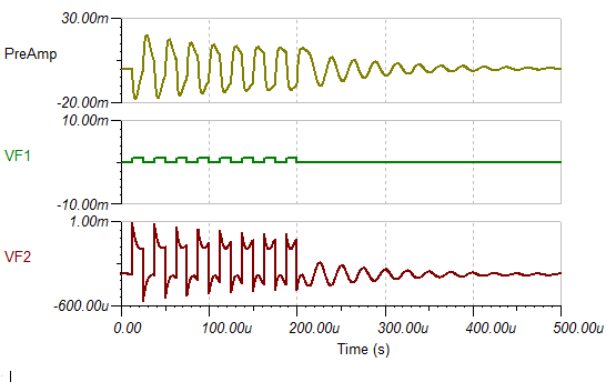
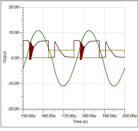
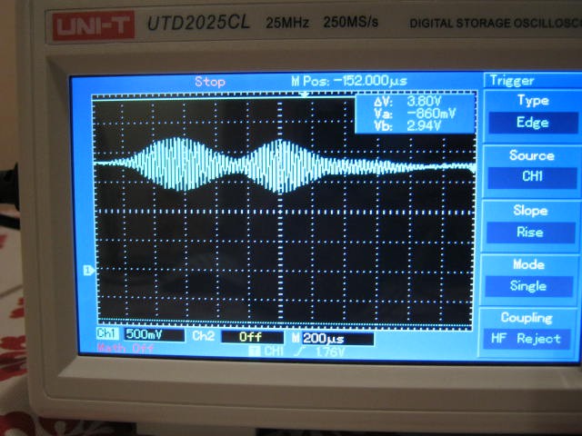
Here is the sensor voltage:
![]()
Okay there seems to be sub-harmonic ringing that matches the choke ringing.
But at least the voltages are nearly 20v pp.
Damping the transmitter sensor with a 1k resistor helps a little:
![]()
and
![]()
On the receiver side I am picking up signals but very erratic:
![]()
The receive sensor (off the transistor collector):
![]()
The transmit and receive signal basically overlap (lots of ringing).
After damping with a 4k7 resistor:
![]()
Better but really still pretty useless.
There is a lot of work required to get these senors working properly!
Scanning Sonar
It seems like the scanning sonar that basically worked before (but not perfectly) is going to be the fastest route to getting the Dalek finished.
So tomorrow I will dig up the hardware and see if I can get it working again.
AlanX
-
I have found a solution to the HC-SR04 problem
10/02/2016 at 06:41 • 0 commentsI have found the problem!
Dale Heatherington said:
"During my experiments I observed that large objects well within sonar range sometimes did not show an echo. Moving them a fraction of an inch resulted in large return echoes. This was caused by multiple reflections arriving at the receiver out of phase. They canceled each other out! The solution is space diversity. Two receiver transducers are placed about an inch apart. They are connected to separate signal processing chains. It's unlikely that both receivers will be in a phase null at the same time so reliably is greatly improved. Now I have three transducers per channel but it works great!" (source: http://www.botlanta.org/ahrc-publications/sonar6)
Here is Dale Heatherington's dual receiver sensor setup:
![]()
This is exactly what I was finding with my sensor tests and with the HC-SR04!
So the answer is not four sensors but eight or twelve.
Well actually all I really need is enough overlap that if a sensor will not read then just average the distance between the two adjacent sensors.
Actually a much better approach is scanning sonar like this:
![]()
Time is running out so the answer is either two sensors per direction (eight all up) or twin sensor scanning sonar.
Time is short so using the existing driver board is preferred.
Unfortunately the driver board does not have room for eight sensors:
![]()
I could add a daughter board with another PCF8574 but a better idea is to trigger two HC-SR04s at a time and the diode OR the returned echos.
The only problem now is that I only have two spare HC-SR04s.
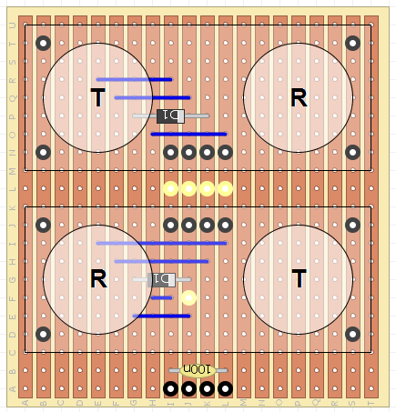
But at least I can test the idea why I am waiting for the new sensors to arrive.
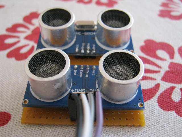
Here is the twin sensor concept (note: I have added a 10k pull-up resistor to the echo output):
![]() The transit and receive sensor pairs are about 36 mm apart (~1/2 wave length).
The transit and receive sensor pairs are about 36 mm apart (~1/2 wave length).So no negative transmit interference pattern (except at 90 degrees to the sensors).
The theory is simple but I did a simple simulation in Excel:
![]()
The theory is that the receivers are far enough apart that both receivers are less likely to be affected by a negative interference at the same time.
The sensor echos are diode ORed, so the first sensor to fire will interrupt the MPU.
The transmit power is doubled as well.
As Dale says, I could stack more of these sensors if increased reliability is required.
Nooooooo!
I assembled the dual sensor with ORed echos but unfortunately it was even more unreliable. I can't win! I do know one of the sensors was not that good but still.
![]()
![]()
I still beleive there is merit in the multi-receiver solution though.
AlanX
-
Sensor Integration
09/28/2016 at 07:35 • 0 commentsSensor Integration
Now that I have something that is basically working, I thought it would be time to think about how I am going to integrate four sensors to the ESP-12E.
The ESP-12E does not have eight free lines after allowance for the stepper control and other planned functions.
Generating in software a 40 kHz drive signal through I2C is not possible (too slow).
It seems like an ideal job for a ATTiny (slave) using I2C to communicate with the EPS-12E (master).
I that case having an LM567 and an ATTiny85 would be a bit of over-kill.
Why not simulate the Phased Locked Loop (PLL) in software on the ATTiny85 (it is something I have previously researched).
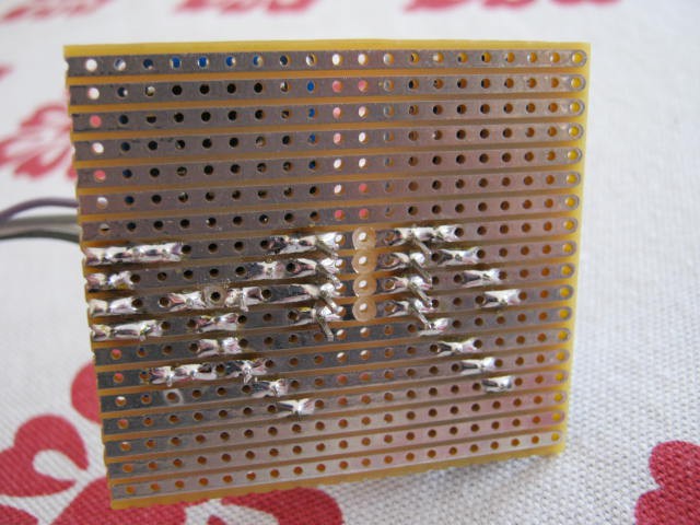
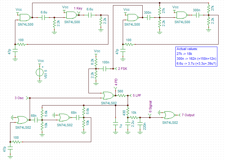
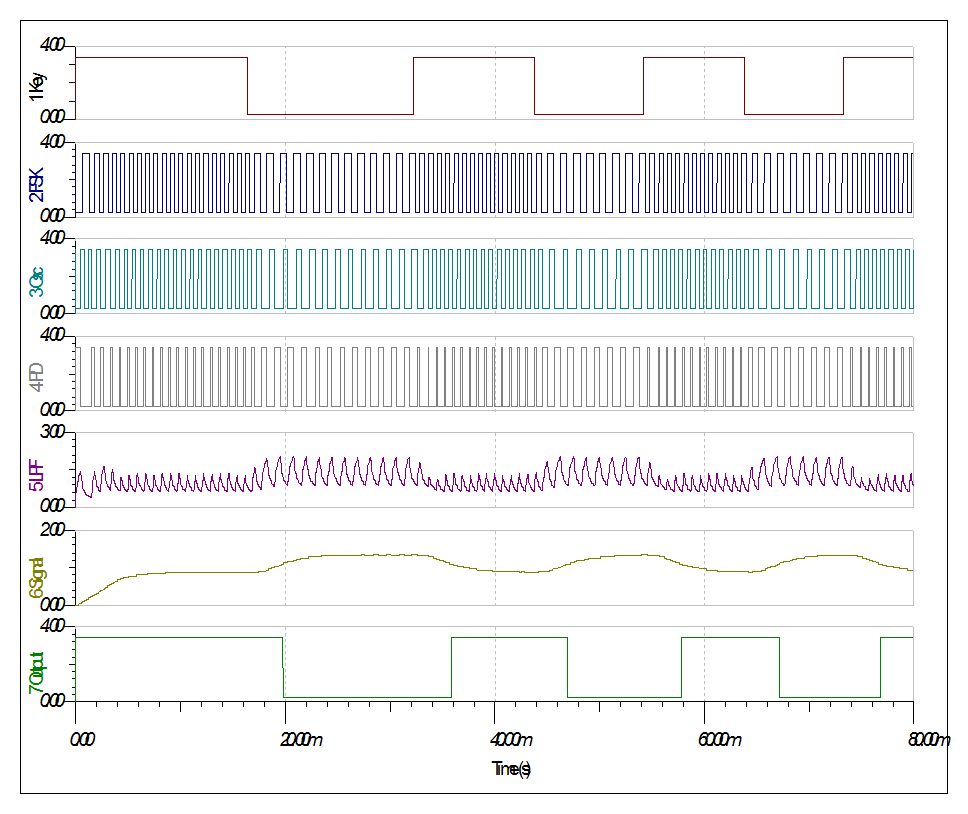
While I am thinking of it, here is my DIY PLL (hardware design using LS-TTL, the actual PLL is the 74LS02 at the bottom of the schematic (beginning with the 2_FSK probe) - yes it is that simple):
And the PPL decoding a signal:![]()
The actual code to simulate the above is not difficult (which you may find surprising).![]()
Another option would a Discrete Fourier Transform (DFT).
A search of the Internet suggest Goertzel algorithm would be a very good choice (someone has even written an Arduino library!).
Here is the algorithm:
double goertzelFilter(int samples[], double freq, int N) {
    double s_prev = 0.0;
    double s_prev2 = 0.0;
    double coeff,normalizedfreq,power,s;
    int i;
    normalizedfreq = freq / SAMPLEFREQUENCY;
    coeff = 2*cos(2*M_PI*normalizedfreq);
    for (i=0; i<N; i++) {
        s = samples[i] + coeff * s_prev - s_prev2;
        s_prev2 = s_prev;
        s_prev = s;
    }
    power = s_prev2*s_prev2+s_prev*s_prev-coeff*s_prev*s_prev2;
    return sqrt(power)/N;
}
(source: Efficiently detecting a frequency using a Goertzel filter - Wilfried Elmenreich)
Note: I modified the return value for rms of signal voltage.
Going through the calculations for an ATTiny85, 25 samples at 125 kHz (K=8) has a centre frequency of 40 kHz and will take 200 us (i.e. 8 pulses). The bin/band-width would be 5 kHz. The 8 bit (0-5v) ADC has a voltage step of about 20 mv.
On the multiplexing problem
A CMOS 4052 (2x4 analog multiplexer) or equivalent would work well here.
The pre-amp could even be on the MPU side of the multiplexer but then shielding of the inputs would become necessary - perhaps not!
Only one analog pin and three digital (output) pins would be required for four sets of sonar range finders (easier than using four ATTiny85 and I2C).
So interface directly to the EPS-12E is a good option.
Need to check out the EPS-12E ADC.
No, the conversion speed is about 83 us (12kHz) but OP report less in loop{} (about 8kHz).
Found an external SPI 4/8 chanel ADC (MCP3004/8) which looks interesting and fast enough (75 to 200 ksps depending on the voltage).
I need to see if a digital version would work for this application.
Simulation of Goertzel Algorithm
Wrote a short C program and plotted the results in Excel.
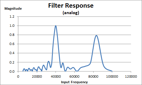
Here is the analog filter response:
![]()
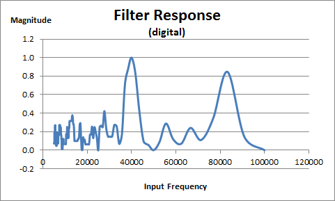
Here is the digital (0 or 1) filter response:
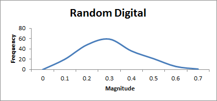
Here is the response to random digital (noise):![]()
![]()
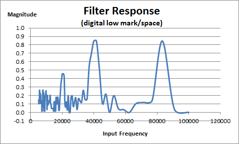
Testing with low mark/space ratio:
![]()
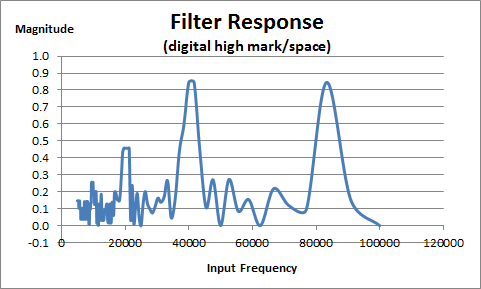
And with high mark/space ratio:
![]()
Although you could build a sonar range finder that just tested for any signal at the pin, the code is pretty neat in that it adds additional filtering.
Especially neat is the digital version version of the code.Should be pretty easy to read a digital pin quickly (one source says 0.527 us on the ESP8266) on any MPU.
Not quite sure!
Not quite sure how to set up the analog/digital interface.
Here is one idea:
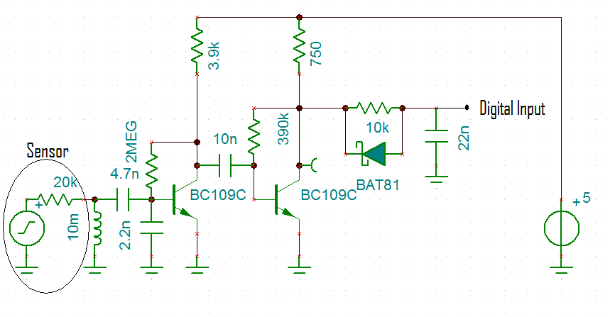
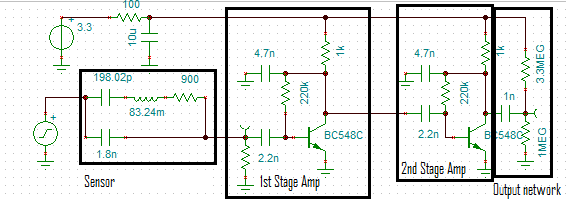
Cascade two amplifiers and offset the output (the input pin of the MPU):
![]()
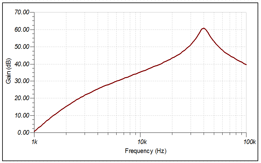
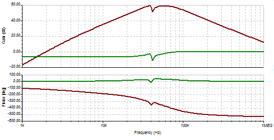
The gain is just less than 60dB:
![]()
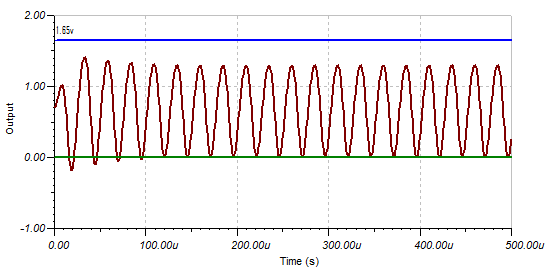
At 2 mv pp (at the signal generator) the signal is less than the MPU input trip point (assumed to be 1.65v):
![]()
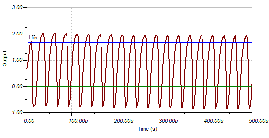
At 10 mv pp the signal will trip the MPU input:
![]()
At 20mv pp the signal is not that much different:
![]()
Now the question is what should the gain be?
The gain depends on the background (signal) noise.
I found this image on the Internet:
![]()
(source: http://www.botlanta.org/ahrc-publications/sonar6)
This author has used an adaptive threshold but for his set up, a fixed threshold of 200 mv pp would work just as well (after removing transmit pulse).
The HC-SR04 (and others) uses variable gain (i.e. gain steps) with time.
A high gain bandwidth amplifier
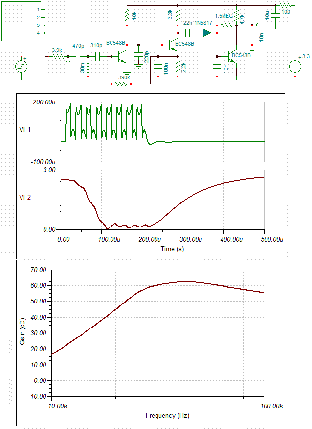
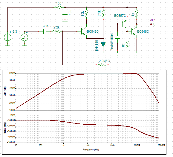
I spent the day designing a new high gain (60dB) high gain band width (60dB at 1MHz) for 3.3v. Here is the result:
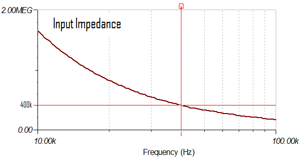
You will notice that the gain is controlled by the "external" resistors (i.e. the 2k2 and the 2M2) just like an OpAmp.![]()
The output voltage (~2 v) is controlled by the diode drop.
The Rolloff capacitor depends on the application (between 100pF and 100nF), higher values are required for lower gains (basically the same as an OpAmp compensation capacitor but not as well behaved).
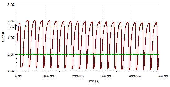
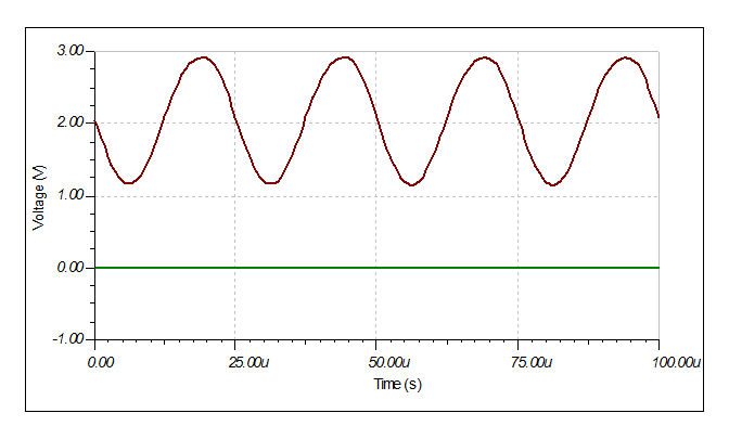
Here is the output for a 2 mv pp input signal at 40 kHz:
The input impedance varies with frequency but at 40kHz is about 400k:![]()
Not bad for 9 components excluding the power supply decoupling (2) and the external components (3).![]()
I wonder if it is stable outside of the simulator?
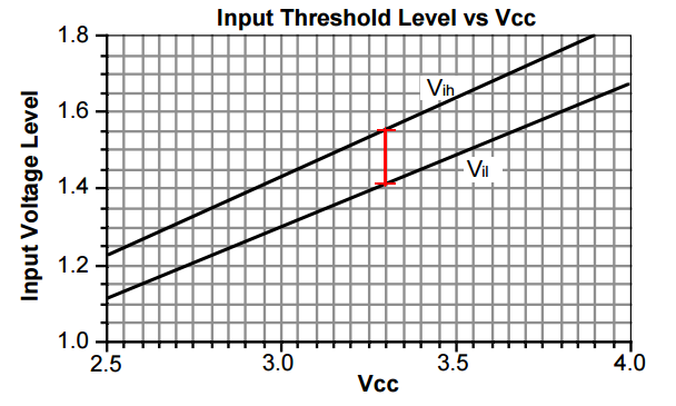
Checking the 3.3v logic trip voltages
In the above images I had assumed that the trip voltage was 1.65v (half the voltage supply). In fact the Vih is 1.55v and Vil is 1.4v (~150 mv hysteresis):
![]()
(source: https://www.idt.com/document/apn/124-33v-logic-characteristics)
Other 3.3v logic families are similar (the TI datasheet stated 1.5v for Vih and 1.4 for Vil (~100 mv hysteresis)).
Data Slicer
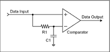
After a day or so I research I determined the approach take by others is a "Data Slicer":
Here a comparator compares the signal against its average DC value (just ignore the schmitt trigger in the circuit):![]()
![]()
The RC constant should have a corner frequency (=1/(2*Pi*R*C)) approximately equal to the "pulse" frequency (=40 kHz).
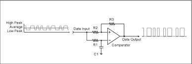
But how do you deal with noise (suppression)? After a few more days searching I found this circuit where the average DC voltage is offset:
So here is my design:![]()
Threshold settings (i.e. the 100k variable resistor) with a 13 mv pp input signal:![]()
- 0% (100k) ~2 mV input signal threshold
- 50% (50k) ~4 mV input signal threshold
- 80% (20k) ~9 mv input signal threshold
In the above design the transistor pre-amp has an input impedance ~4k and a gain of x18. The data slicer corner frequency is 40 kHz.
Conclusion
This is a very interesting approach and deserves further attention but since I have worked out why the HC-SR04 does not work and how to fix it. I will leave it for now.
AlanX
-
Conned Again
09/22/2016 at 10:07 • 11 commentsConned Again
I bought these 15 mH inductors many many years ago. Finally I have a project to use them in. Here is the receiver part of the sonar range finder I have been designing:
![]()
(Note the 15 mH (=153) inductor on the left hand side.)
Before building the transmitter side (on the right of the vertical wire link), I wanted to check that it was working.
Checked the collector voltages:
- a bit too low (Tr2 was 1.9v instead of 2.5v)
- the transistor gain is higher than expected (450 instead of 290)
- easy fix, increase the feedback resistor.
Check the output for noise:
- Less than 1 mV pp (transistor noise) with "impulse" noise at less than 10 mV pp (from the nano providing the 3.3v power?).
Set up a HC-SR04 as a sound source and test the receiver:
- No signal detected?
- Measure the sensor directly and yes the signal is there.
- Check the base of the first transistor - nothing!?
Check for miss-wiring etc., all okay.
Think about it and decide it has to be the inductor:
- Removed the inductor and tested for the presence of a signal - yes the signal is now present.
What went wrong?
Hand calculated the resonance frequency - close enough.
Do ferrites age? Anyway, the inductor cannot be 15 mH.
Checked the DC resistance, less than 0.6 ohm (including the fuse of the multimeter) which is just too low when compared to a 4.7 mH inductor I have (which is about 11 ohm).
Peel the jacket off and count the windings - 22 turns!
![]()
Checked some ferrite datasheets and my estimate is about 15uH not 15mH.
I have been conned!
I have some ferrite beads (FB-43-2401) that with 171 turns of 28 AWG (i.e. ~0.32 mm diameter wire) would make a 15 mH inductor. No, threading 4 to 5 m of fine wire does not sound like much fun. I will have to order some from ebay.
The Sensor Test
Measuring the sensor directly gave voltages in the order of 100-200 mV with the sound source just 10-20 cm away. That is great, the sensor is working as expected BUT is was ringing for 100s of microseconds! Looks like the sensor will need to be damped (properly loaded). In theory, the transistor is matched to the sensor so when powered it should be damped.
Rework the Design Again
Found a toroid ferrite at the local electronics shop:
- 18mm x 10mm x 6 mm L8 material and no other data.
Found a datasheet for L8:
- 1500 ui
- 300kHz max frequency (for ui)
Found a webpage to calculate Al:
- 1.06 uH/t^2
Magic, 120 turns for 15 mH.
Reworked the matching networks for both the receiver and the transmitter and reduced the transmitter choke to 4.7 mH (which I have on hand).
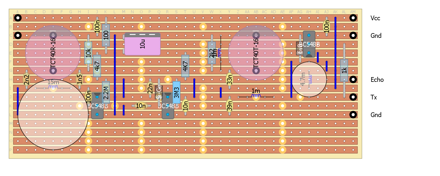
Here is the updated strip-board design:
![]() Here is the receiver:
Here is the receiver:![]()
And here is the transmitter:
![]()
Damping the Transmitter and receiver Sensors
I am a bit worried about ringing of the transmitter and the receiver sensors.
An unloaded receiver sensor rang for 100-200us when 15 cm away from a HC-SR04.
The matching networks should load the sensors but I have added provision resistors if ringing is still a problem when in-circuit (10k for the receiver sensor and 1k for the transmitter sensor).
Success
I wound the 15 mH inductor last night.
120 turns on a 18mm x 10mm x 6 mm toroid of L8 material.
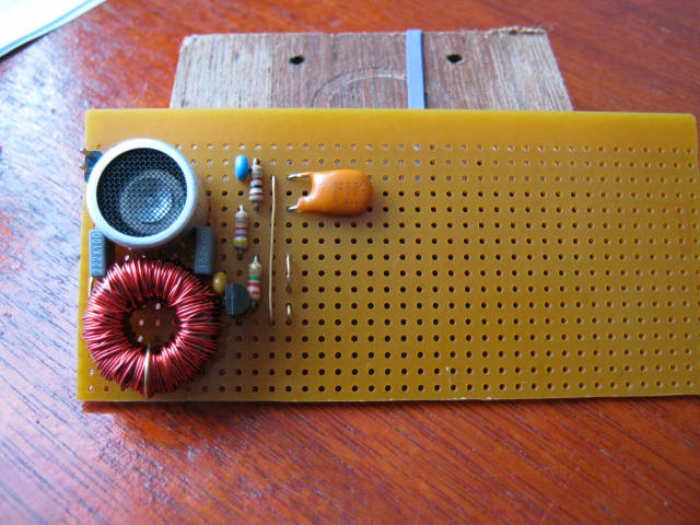
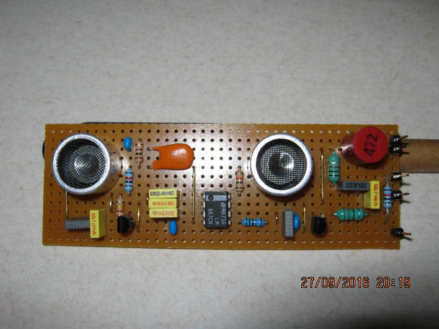
Here is the first stage of the transceiver:
![]()
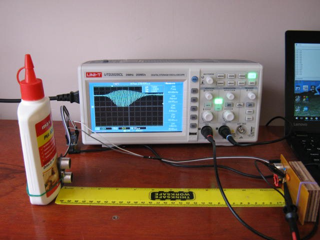
Here is the test set up using a HC-SR04 as a signal source (30 cm away):
![]()
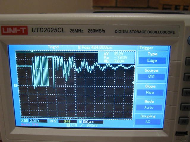
An here is a closeup of the oscilloscope:
![]()
Yes the output is rail to rail! The sensor Q is quite evident with the 300 us ramp up (3 major divisions). Note that the transistor output hits the rails after 200 us. The signal decay is about 400 us.
How strong should the signal be?
For this set up the sensor should (my estimate) produce about 30 mv rms (~100 mv pp).
The display matches the expected transistor performance. based on Tina. So all is good.
I have made provison to further load the sensor to damping the ringings but it is too soon to tell if it is actually required for my application.
Demodulator
Added the next stage (the demodulator), it works but it is not very sensitive or stable.
I think unintended demodulation from the first stage is upsetting the bias of second stage.
I am not sure how I can fix this, at least easily.
Perhaps I should use a 567 tone decoder instead.
Modelling the TCT40RT-16 receiver sensor
I thought it may be of some value to model the receiver sensor.
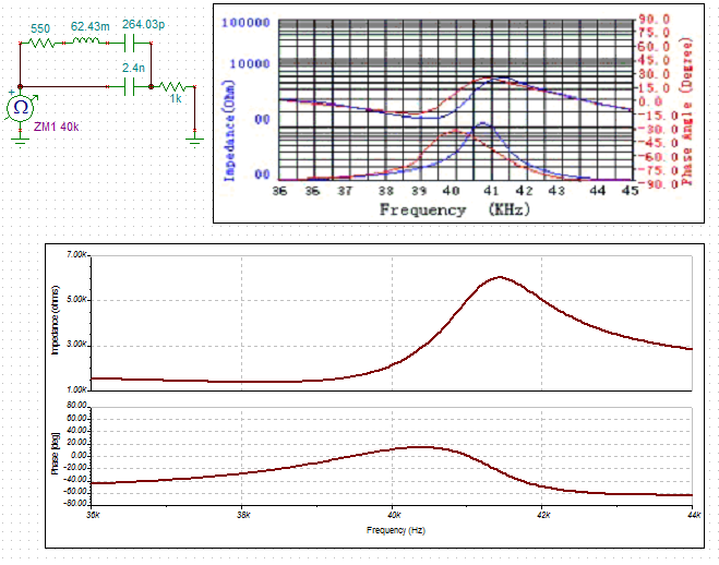
So I measured the parallel and series resonance off the datasheet (39.2 MHz and 41.3 MHz).
The datasheet is not clear which sensor but the parallel capacitance is stated as 2.4 nF.
From the above I calculate 62.43 mH and 264.03 pF for the series components.
The parallel and serial impedances measured off the datasheet are 1.5k and 6k.
I could not get a match for these values by adjusting the series resistance alone so I added a 1k resistance to lift the impedance.
Here is my equivalent circuit:
![]()
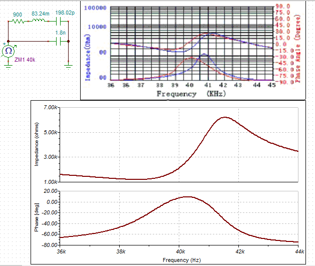
Here is anothe attempt that is closer but without the 1k resistor (I changed Co from 2.4n to 1.8n):
![]()
I have had no luck with the transmitter equivalent.
Yet another receiver design
If you are sick of yet another design spare a thought for me!
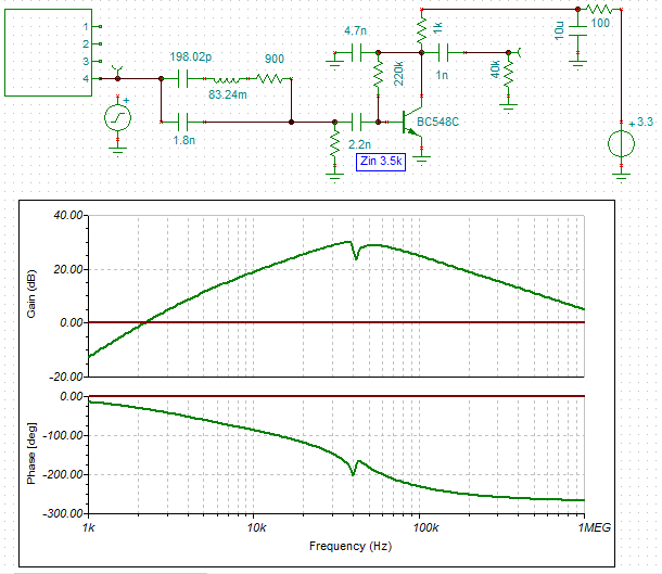
Anyway, I dropped the input impedance to 3.5k ohm (so I can drop the matching network). I looked at an active filter but lost too much gain:
![]()
Here is the transient response (at 40kHz):
![]()
I designed a 567 tone decoder circuit.
The tone decoder can detect signals down to 25 mv rms (10 mv rms with a 130k pull down resistor on pin 1). The bandwidth at these voltages is small (2-4%) so the decoder oscillator needs to be spot on. The main down side is that "pull in" can take up to 10 cycles (250 uS). Recovery time would be similar.
Here is the board layout:
![]()
Here is the assembled board:
![]()
I have had to migrate back to 5v as the LM567 does not work at 3.3v.
No problem for the transmitter (3.3v drive is okay).
The Echo will however be 5v, but as it is feed though a 10k resistor this will not hurt a 3.3v MPU (but about 100uA will flow through the protection diodes).
I have not tested the transmitter yet - tomorrow
The receiver works
It picks up the initial transmit pulse and a reflection or two depending on the sensor orientation.
There is almost a continuous ringing/noise of about 5 to 10 mv pp (just below the LM567 detection threshold). Very similar to the transient response above.
I will have to experiment with damping the sensor with a load resistor.
AlanX
-
DIY Sonar Sensor
09/10/2016 at 04:53 • 6 commentsDIY Sonar
First lets start with the expected signal level.
Based on the 400RT160 datasheet (http://www.robot-electronics.co.uk/files/t400s16.pdf) and the Pro-Wave Electronics Corporations application note (http://www.prowave.com.tw/pdf/an0508309.pdf) the approximate signal level is in the order of 1 to 10 mV:
400SR/T400 Transmitter SPL 117.0 10v rms at 30cm Power adjustment -6.0 5v rms Distance loss -28.5 =20*log10(30/x) Distance 800 cm Wave absorption -1.6 =-0.002*cm Receiver sensitivity -57.0 3.9k load Conversion uBar to V -74.0 Signal -50.1 dB Signal 3.119 mV Here I have assumed 5v rms transmitter voltage rather than 10v rms as per the standard.
The sensor input impedance is 3.9k ohms.
The signal input (3 mV) suggests a minimum receiver gain of 60dB (x1000) is required.
I have designed two circuits (more options are available for consideration).
The first is a two stage transistor amplifier (74dB gain based on the Tina simulation) followed by a diode detector. For this circuit I assumed the sensor impedance was about 20k as I had not found the right datasheet.
![]()
A very important note is that I have not designed the supply noise filtering for this circuit. With 74dB of gain (x5000) and the input in-phase with the output, the risk of feedback is almost certain.
Hers is the frequency and transient analyses:
![]()
![]()
The second version is less sensitive but should not suffer feedback oscillation:
![]()
The choice of detector diode determines the receiver sensitivity. A germanium diode would work best followed by schottky diodes and lastly conventional silicon signal diodes.
![]()
Preliminary Transistor Amplifier Design
The preliminary transistor amplifier design is as follows:
Preliminary Design Value Units Transistor BC548B Beta (2mA) 290 Vs 5.0 v Vc 2.7 v Rc 4.70 k Ic 0.489 mA =(Vs-Vc)/Rc Beta 236 =log10(2/1000)/log10(Ic/1000)*Beta(2Ma) Zin 12.1 k =Beta*25/1000/Ic Rb 0.99 M =(Vc-0.65)*Beta/Ic Av 108 =Vc/25*1000 The design formula works okay except that Tina predicts a much lower gain.
Still it is a useful starting point.
Pre-selection LC filter
In both these sonar receivers I have used a pre-selection LC filter to reduce out of frequency response and to match the sensor to the transistor input impedance.
I used capacitor tapping to scale up the impedance in the two circuits:
RL~RS*((C1+C2)/C1)^2, where C1= 4n7F and C2=2n2F in circuit 2
In this case I used Tina to determine the exact capacitor values but there are formulas for this if you look on the Internet.
Another design
I also played with this one:
![]()
And:
![]()
The low limit of detection is in the order of 100uV which is a bit of overkill.
The second version looks about right to me if I use a Ge diode (or a Ge silicon clone).
Probably time to make a prototype using strip-board, here is a layout:
![]()
Transmitter
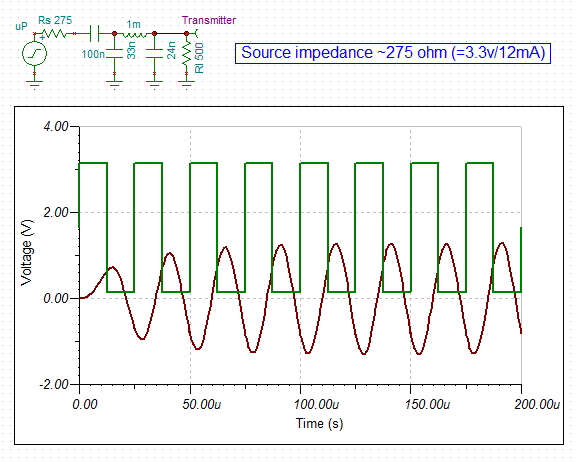
Based on the limited data on the EPS-12E the digital pins can source/sink 12 mA. This is similar to the AVR specification. So an estimate of the "source" resistance is 275 ohm (=3.3v/.012A). The effective source resistance is probably lower. The ultrasonic transmitter has a load impedance of about 500 ohm (based on the datasheet). So I matched the source impedance ad load impedance using a Pi network and updated the strip-board design. I calculate the output power to be 1.6 mW (2.55v pp based on Tina). Here is the Tina schematic:
![]()
Here is the strip-board design:
![]()
Checking the range:
400SR/T400 Transmitter SPL 117.0 10v rms at 30cm Power adjustment -20.9 EPS-12E single pin 3.3v into Pi network Distance loss -4.9 =20*log10(30/x) Distance 53 cm Wave absorption -0.1 =-0.0019*cm Receiver sensitivity -57.0 3.9k load Conversion uBar to V -74.0 Signal -40.0 dB Signal 10.0 mV Receiver detection limit A return range of 53 cm (26.5 cm one way) is practically unusable!
Okay, I either increase the transmitter power or increase the receiver gain.
Increasing Receiver Gain
Looking at the receiver I had a play with reducing the supply voltage down to 3.3v to eliminate the need for a 5v supply. The sensitivity "reduced" to 20 mv (from 10 mv):
![]()
It would seem that I should revisit the two transistor pre-amp schematic.
Increasing Transmitter Power
In order to increase the transmitter power I have to reduce the source resistance by buffering. Many options but here is one that I looked at:
![]()
The output is 5.5v pp which equated to 6.4 mW into a 500 ohm load.
In theory you could push this circuit for higher power but the Q increases rapidly making tuning necessary and tricky. Higher Qs also slow the power ramp up.
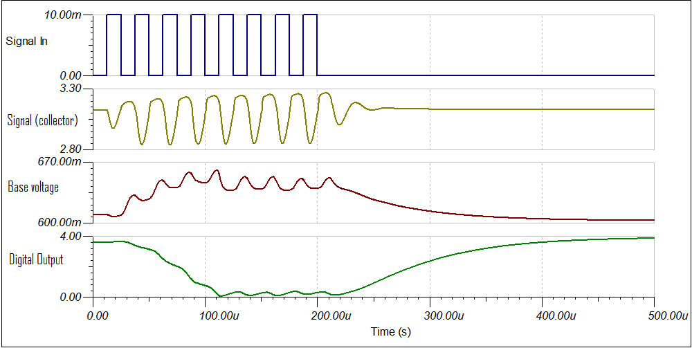
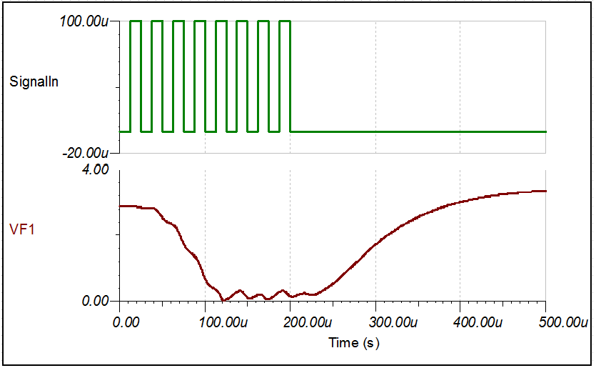
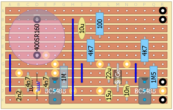
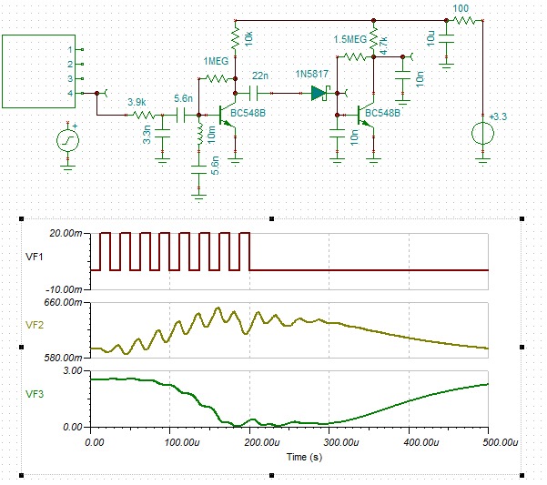
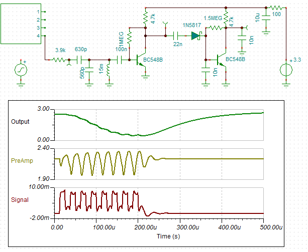
Revised 3 transistor design
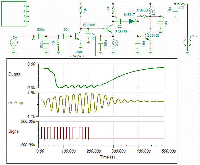
I have revised the design for 3.3v and a simplified "T" high pass filter matching network. I have added a 220pF to roll off the high frequencies faster. Here is the schematic and the response to a 200 uV signal:
![]()
(Note:the 3.9k resistor on the input is part of the sensor.)
The receiver can detect a 200uV signal which is more than enough for the low power transmitter:
And here is the signal analysis:![]()
400SR/T400 Transmitter SPL 117.0 10v rms at 30cm Power adjustment -20.9 EPS-12E single pin 275 ohm source impedance Distance loss -28.5 =20*log10(30/x) Distance 800 cm Wave absorption -1.6 =-0.0019*cm Receiver sensitivity -57.0 3.9k load Conversion uBar to V -74.0 Signal -65.0 dB Signal 0.6 mV Detection is about 0.2 mV Now I have to source the inductors and capacitor values I have chosen and then update the strip-board design.
Strange
Well I was looking at what inductors I had and what I had to buy.
A 30 mH would be an ebay order (2-3 weeks) but I had some 15 mH. So no problem, just double them up.
But I though I would check if I can come up with a 15 mH design.
Now, I had noticed that the webpage I was using gave component values that were a bit off (peak at 30 kHz instead of 40 kH etc). I had countered this by optimising the design in Tina (slow but effective).
Up until now I thought it was due to the influence of the transistor.
But i noticed that the components values where not the same as a practically identical but different webpage.
Upon further investigation (and calculating the component values by hand) I found the webpage I was using was wrong. Tina said my calculations were correct.
So I started using the new webpage but even then some of the networks gave wrong answers. I some cases the component value labels were swapped around.
So I built a spreadsheet for the calculations. All good. I worked out a band-pass network using just one 15 mH inductor:
![]()
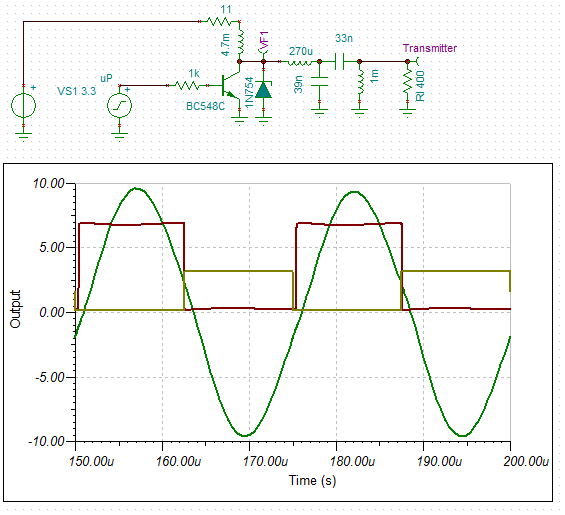
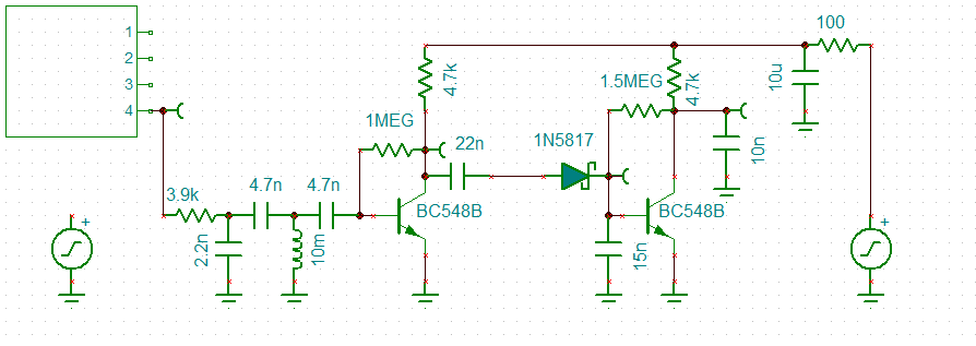
Updated Transmitter
Next was to check the transmitter.
I decided to look at a single transistor design using a collector "choke".
A two stage design is required else the Q would be too high.
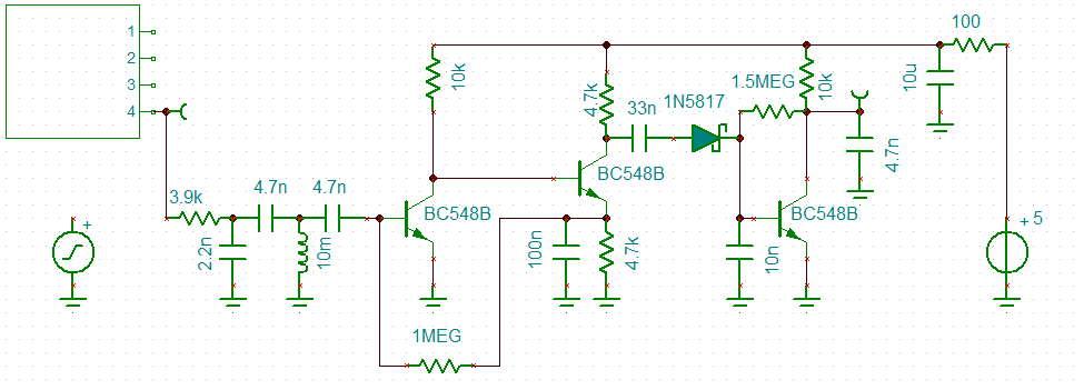
Here is the design I can up with:
![]()
Because the circuit is driven by a square wave, the "choke" generates inductive voltage spikes.
I tried a capacitor at the base of the transistor (did not work) and a diode across the 'choke".
The diode worked but I was still concerned about the inductive spikes (~0.7v) superimposing on the power supply.
The final design uses a 6.8v 400 mW zener to clip the inductive spike.
Even Stranger
Following is the Tina simulation with the zener diode:
![]()
You will notice the ringing (~5.3 MHz, this should not be a problem).
What you will not know is that the output voltage (21.6v pp) has increased (from 17.3v pp) when the zener was added.
So the inductive power has been put to good use!
The output power has increased from 75 mW to 116 mW.
I have heard of parametric amplifiers but I am still quite astonished.
Updated Signal Maths
400SR/T400 Transmitter SPL 117.0 10v rms at 30cm Power adjustment -2.3 EPS-12E single pin 275 source impedance Distance loss -28.5 =20*log10(30/x) Distance 800 cm Wave absorption -1.6 =-0.0019*cm Receiver sensitivity -57.0 3.9k load Conversion uBar to V -74.0 Signal -46.5 dB Signal 4.8 mV (rms) So with the new transmitter, the expected signal is about 5 mV (rms) at 800 cm return distance.
So I can use the two transistor receiver as it is sensitive to about 5 mV (pp):
![]()
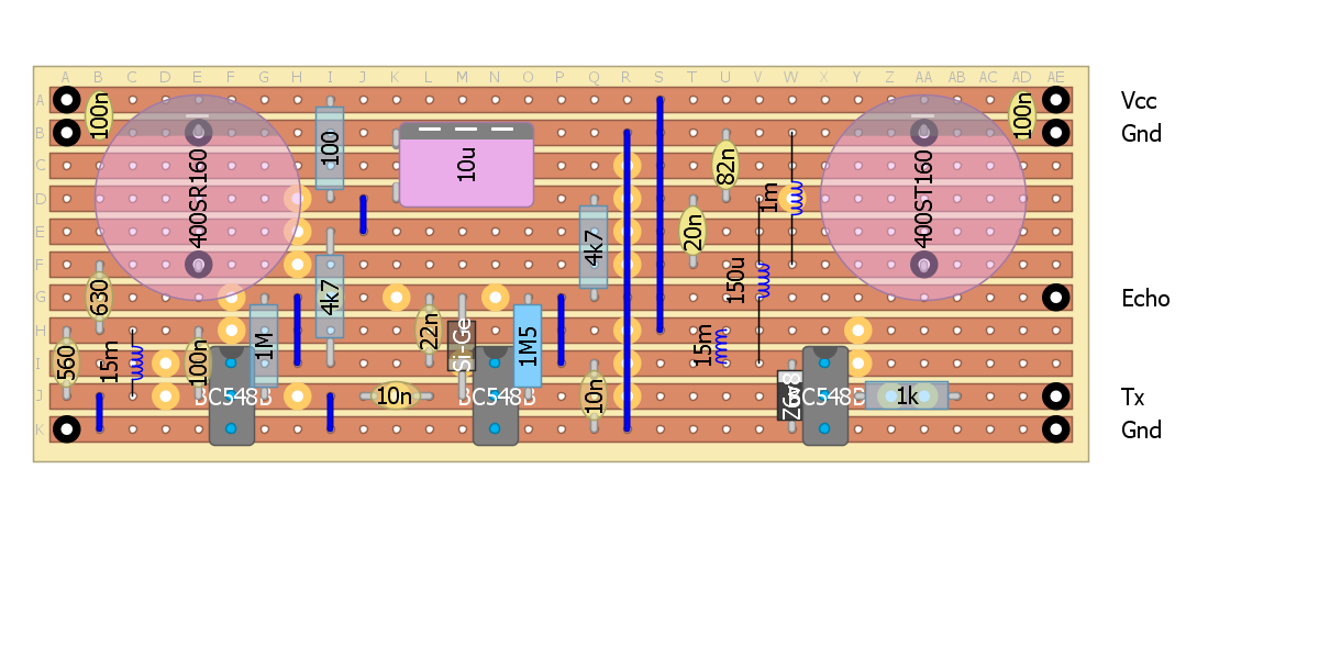
Back to the strip-board design!
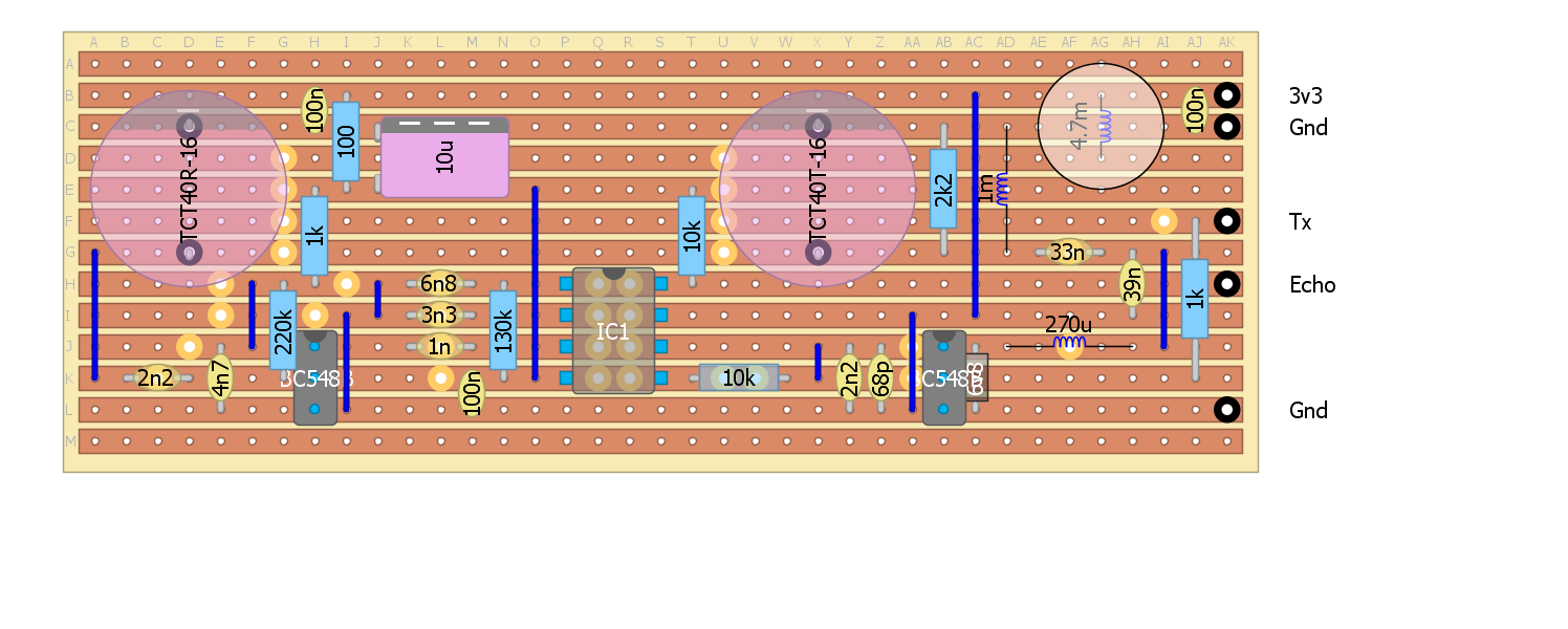
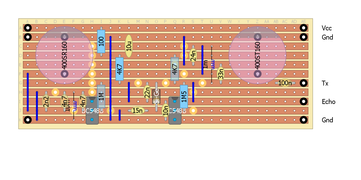
Here is the latest design layout:
![]()
Parts
I wandered down to the local electronics shop and purchased enough components for 5 sets of sensors.
The only hiccup was that the bag of sensors that I order on ebay last February (which were meant to be pairs) were all transmitters.
Still I have two other sensor receivers that I can use for test-work..
So I am not going to be able to finish the fours sensors I need for the Dalek in the next two weeks. Not good. Time is running out.
AlanX
-
Software Build
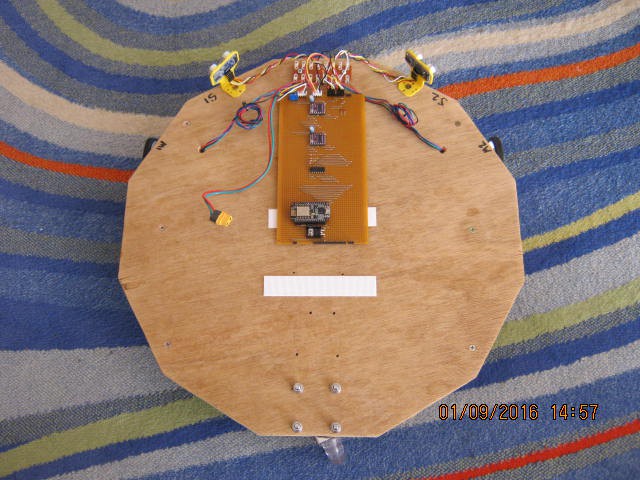
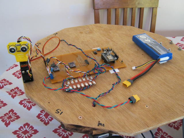
09/01/2016 at 08:08 • 0 commentsHardware Complete
The hardware is complete, here is the testbed:
![]()
The battery is missing (being recharged after a day of debugging).
The white strips are Velcro.
The testbed has been set up as an autonomous robot using the ultrasonic sensors to stay away from objects.
Software Problems
It basically works but there a problems (what is new!).
Currently making sure the sensor and stepper drive logic works.
The main problem is that the sensor (or sonar) ticker interrupt (every 250 ms) interferes with the stepper pulse ticker interrupt (every 10ms) as stepper pulses appear to be lost). I assume that the sonar ticker interrupt (that can take up to 40 ms (with time out) to return) is blocking stepper ticker interrupt. The ticker interrupts do not appear to be the same as normal interrupts as the sonar routine waits for a real interrupt on D3 and is working.
It is not unreasonable to assume that Ticker is blocked while servicing a ticker interrupt.
Worked it out.
I moved the pulse timing loop out of the interrupt routine and into loop(). No difference!? Okay worked it out. Ticker is not interrupt based but "Blink without delay()" based. Better than nothing I suppose. Okay, recoded on this basis and the motors work fine but the sonar no longer works.
Motor Noise
The sonar work fine until I turn on the steppers. The interrupt line must be picking up the stepper noise. It was okay before because the sonar blocked the stepper pulse during the echo period.
So now I have to research noise suppression.
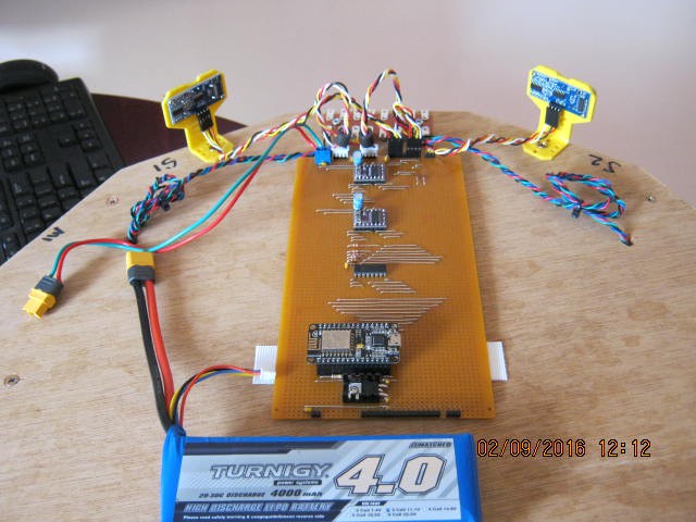
Noise Fixes
- Added 6 decoupling capacitors (0.1uF) to the 3.3v, 5v and power in lines.
- Added 4 decoupling capacitors to the DRV8825 motor outputs (my steppers have 58 mH inductance for each phase so the resonant frequency would be about 2 kHz, so no problem).
- Add two ferrite beads to the stepper cables (why not!).
- Twist paired all the cables.
See image:
![]()
Results- The EPS-12E is now okay with serial while the motors are running (five stars)
- The steppers are much easier on the ears (three stars)
- The ultrasonic sensors are just as bad/unreliable with the motors running or not (three stars).
Ultrasonic Sensors
I think I forgot how bad ultrasonic sensors are! I did a sonar project a while back so I should have known:
![]()
Filtering Bad Sonar Reads
Filtering the bad reads is problematic. Simple averages don't work well.
With the sonar project I used the median value of three sequential reads.
This time I used two similar consecutive reads with "too far" over-rides.
This work as well as can be expected, but the code need tuning.
It still struggles to get through the doorway and still crashing into walls.
Here it is when it works (turning to avoid the wall):
And later (going straight):![]()
![]()
Sensor Check
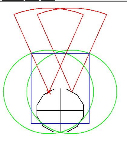
I thought it was time to draw up the sensors to "engineer" the direction they point and the correct range trigger.
So here is my sketch:
![]()
I should point the sensors forward and set the range to 50 cm (assuming a 45 degree aperture based on a datasheet I have).
This gives full frontal coverage and 640 mm wide window.
But the problem is that the sensors do not detect the walls as the angle of incidence is too low (~22.5 degrees).
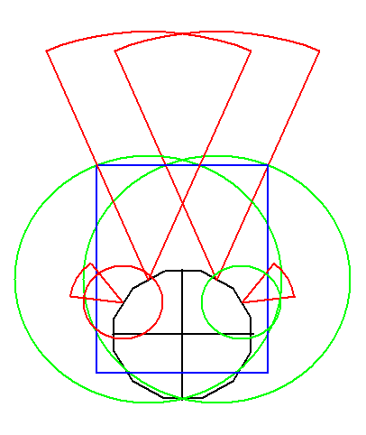
I need four sensor! Two short range (at 60 degrees with 15 cm range) to detect the walls:
![]()
The forward sensor worry me a little because they are only 14 cm off the ground so expecting a range of 50 cm not going to be reliable (some back-scatter off the ground is likely).
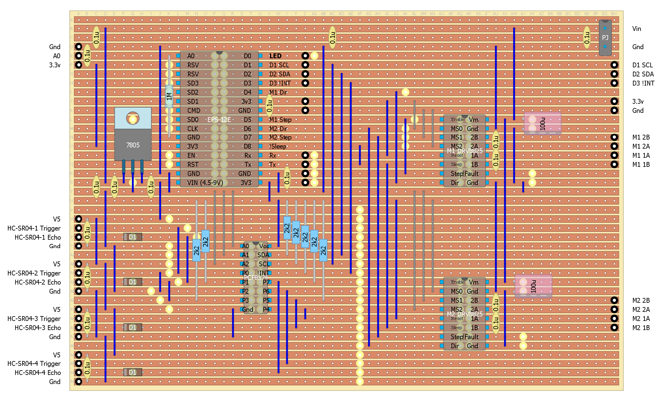
Board Redesign
It looks like I will need four ultrasonic sensors and the PCF8574 is the obvious choice for managing these.
I have four spare ESP-12E digital pins so I should move the two sets of stepper direction and step lines off the PCF to make room for two more ultrasonic sensors.
The board layout needs a rework anyway. It would be a good idea to move the sensors away from the DVR8825s.
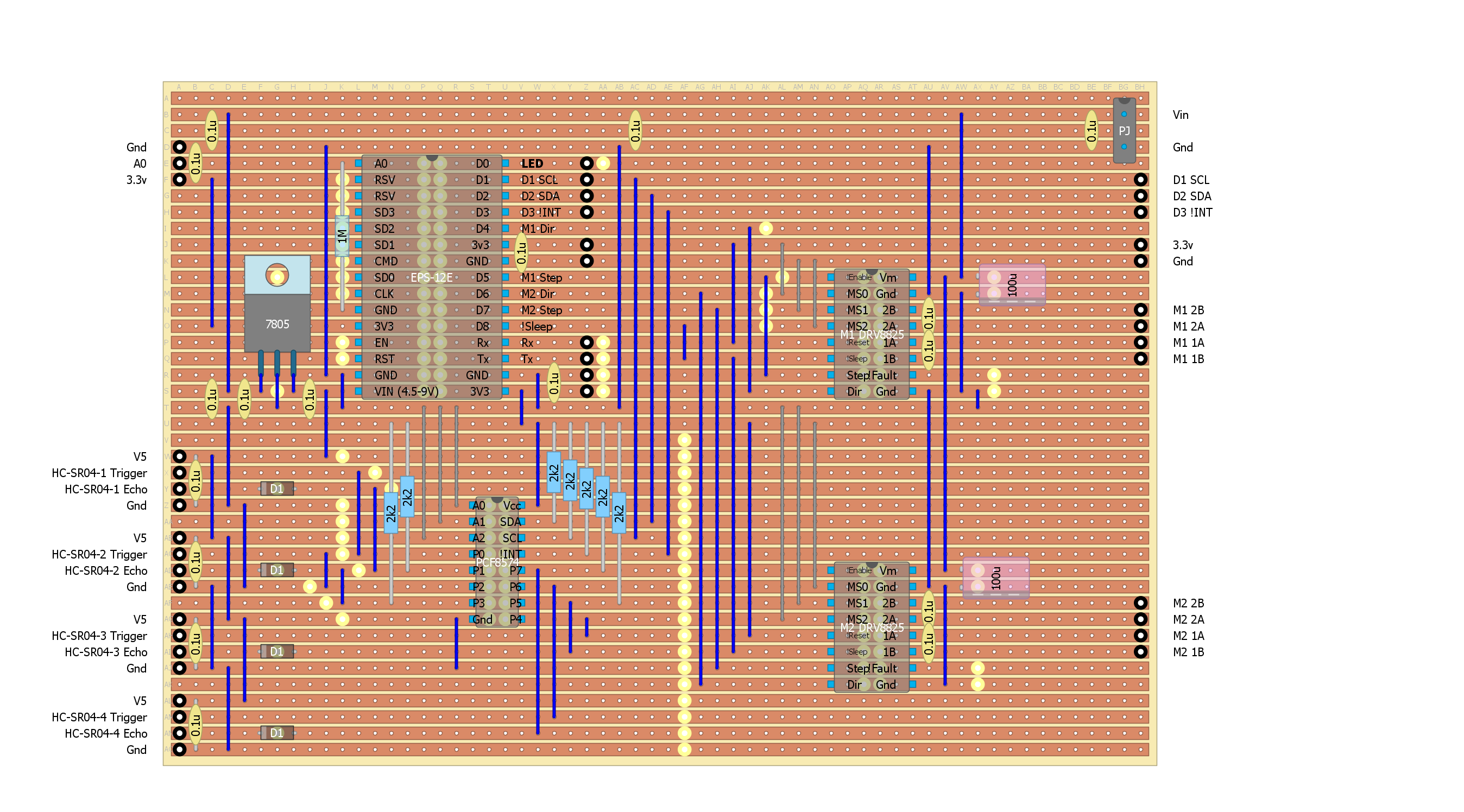
So back to the drawing board!
Spent a day resigning the board. Here is the design:
![]()
Had some work to do at the partners house (fixed 4 leaking taps and swapped out the washing machine).
But I did manage to find 4 hours to assemble the board.
It powered up okay (good sign) but I need to re-code the ESP-12E for the new board.
How hard is this meant to be?
Now I have to say it has been surprisingly difficult getting this rather simple project working.
This is the sixth board I have used:
- Arduino UNO and 2x L298N (these driver boards are useless)
- Arduino UNO and 2x Monster Motor Boards
- Ardunio Nano, Bluetooth (not recommended) and 2x A4988
- Wemos D1R1 (WiFi) and a Protoneer V3 CNC shield using 2x DRV8825
- EPS-12E, PCF8574, 2x DRV8825, 2x HC-SR04
- EPS-12E, PCF8574, 2x DRV8825, 4x HC-SR04
I have run into electrical noise issues, real headaches from the stepper motor noise and unreliable sensors.
Although I destroyed the third board with a loose battery wire, at least I have not destroyed any other board so far.
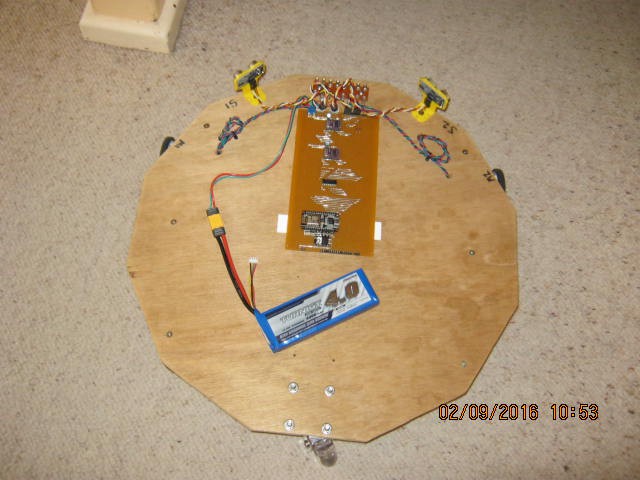
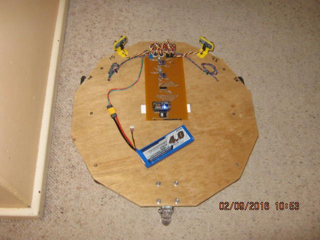
New Code and New Board Installed
I coded the ESP-12E for the new board this morning.
Those ultrasonic sensor give me a headache and make me nauseous.
But the four sensors are working after finding I forgot to solder a ground link.
Have to stop as I am going out for Father's Day lunch (best not to be too sick!).
Here is the test-bed ready for testing:
![]()
Ultrasonic Sensor Aperture
What I did find out is that the minimum angle of incidence off a plywood plate is about 60 degrees.
This also suggests that the effective angle of aperture for these sensors is more like 30 degrees.
Checking with a hand about 15 to 20 cm away from the sensor and it only detected the hand inside 15 degrees (i.e. a 30 degree aperture).
So the wall sensors will need to point at 75 degrees rather than 60 degrees.
I had a noisy sensor, the one with the cable extension (removing the extension resolved the noise).
The board and code seems to be working within expectations for the sensors.
If I had realised that the ultrasonic sensors had such a small aperture I would have gone with the sonar version using a servo to scan the path ahead.
Motor Control
The motor control works as expected except that the serial will not work with ticker running a 10 ms clock.
Overall Performance
In a word: dreadful. Certainly software tuning will help.
It can detects forward objects and the presence of a wall but it is very slow to respond.
Filtering out the bad readings takes time (assuming that is the main issue).
It would have been easier to use a servo and a sonar set up.
Next Steps
Not sure what to do next. It is just not good enough at the moment.
The hardware seems to be as good as can be expected.
I was checking the code and found some errors and better ways of doing things.
It is looking more promising.
I am going to wear earmuffs from now on as the ultrasonic sensors are driving me crazy (particularly if I pulse them slowly).
I hate these ultrasonic sensors
I re-coded the sensor loop to stay with a sensor until it got two similar readings (within 10 cm) before moving to the next sensor.
Also anything beyond 100 cm is set to 100 cm.
Depending where you point the sensor it may never return consistent readings.
Yes the entire stepper system was turned off.
Sensor 3 was the worst but all the other sensors could be made to fail.
Thinking about how it might be failing (i.e. time out), I slowed the cycle down from 50 ms to 100 ms.
Now it does return (sometimes after four or five fails).
Time out is meant to be 38 ms but obviously it is much longer.
Checked the power supply line with the scope and it is clean.
Sensor 3 has timeouts up to 110 ms. I replaced this sensor but no real improvement.
Tried shielding the sensor electronics with aluminium foil, no improvement.
These Chinese ultrasonic sensors are useless
I don't think I can fix these sensors. They give random readouts when out of range.
I would guess they have automatic gain control and end up listening to noise when out of range.
Thus the random out of range readings.
I bought 8 of these (3 different brands) and 3 have already been binned.
I can't even fit the last two to the mount as the PCB mounting holes are too small.
I binned 2 of 3 sensors (two different types) just for my sonar project.
Now there are more expensive (non-Chinese) sonar sensors out there.
Very likely these will work perfectly but the at more than ~$50 a piece I am not keen to try.
DIY Ultrasonic Range Sensors
If I want ultrasonic range sensing I will have to build my own.
After the sonar project I did buy a packet of sensors with this in mind.
I am not looking to sense far objects in this case so a high power transmitter circuit and a low noise pre-amplifier are not required.
More research! So this project is on hold until I come back from holidays.
AlanX
My Dalek Build
For next Halloween I want a Dalek for "Trick or Exterminate"
 Here is the response for the active filter (the IC2:C):
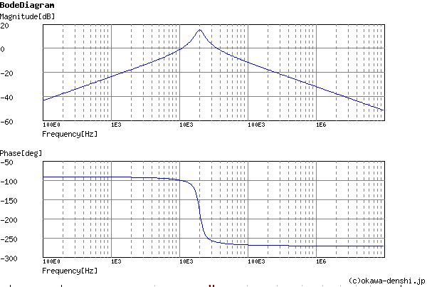
 So it would appear that either a very fast digital read (>1 Mhz) or the analog read (=125 kHz on the ATTiny85) can work.
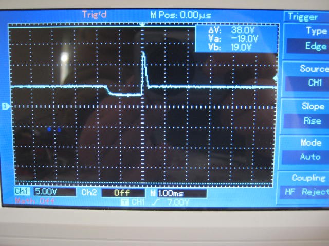

 Here is the updated driver board (with a separate power supply for the servo:
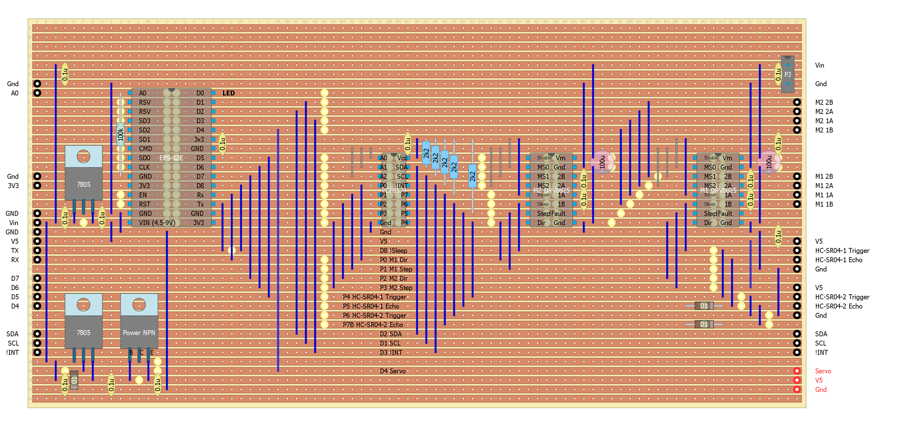
 Had a play with the servo pulse constants (further refinement still required):
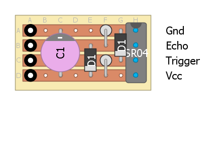

 The transit and receive sensor pairs are about 36 mm apart (~1/2 wave length).
 Here is the receiver: