agp.cooper
-
R6502B
08/25/2016 at 07:56 • 0 commentsR6502B
I had a PCB for one of these old time microprocessors manufactured.
They have arrived, three weeks from China - not bad).
But I am caught out in that I have done nothing on the software side, have no keyboard or display!
Software
Originally I was going to use BASIC and my keyboard and some sort of video display. But porting this (my IO and memory map are non-standard) will take time. On the 6502 site (http://www.6502.org/source/) are some simple monitors. VTL02 (VTL-2 for the 6502) by Mike Barry looks like a good starter. Particularly as the header contains the keyboard IO equates etc that I will need.
I don't have all the components (74LS132 are a bit hard to find) so I did a mail-order. That will buy me two weeks.
I will have to patch something up for keyboard and a display to get going as well.
AlanX
-
Indecision
08/23/2016 at 03:22 • 0 commentsIndecision
I am in two minds whether to go as a single board of to split the board into two?
Here is the a schematic with the keyboard separated from the PLA:
![]()
The advantages are:
- One project becomes two smaller projects.
- A smaller footprint (the boards can be stacked).
- I can finish the keyboard layout and get the PCB board made.
- I can drop the PLA if I go for a microprocessor project.
I think getting the board made (as it takes four weeks) sounds like a good idea.
Stacking the boards (the PLA underneath) seem pretty straight forward.
AlanX
-
Updated Physical Design
08/19/2016 at 06:36 • 0 commentsUpdated Physical Design
I bought some cheap(?) 279 mm x 215 mm x 3.5 mm birch plywood some time ago.
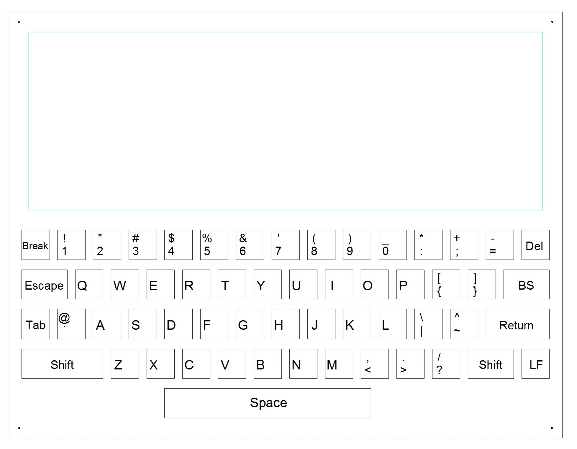
So I have rescaled the keyboard to fit. I only need half the area for the keys:
![]()
This is only the top layer (one of five excluding the PCB). The light blue (cyan) area is reserved for the electronics (which are located underneath) and will be trimmed back once the PCB design has been completed.
CNC Milling the Boards
Splintering is a problem when milling cheap wood. To minimise, I have given the first board a light coat of Estapol to seal the surface and will trace the design with an engraver bit first. Then I will use a 0.8 mm end mill to cut out the keys. There are 4x 1 mm diameter holes in the corners to help with dreaded alignment problems. I will likely make these 3 mm in diameter to service as assembly bolt holes.
I have not worked out what to do with the lettering/symbols.
AlanX
-
The Hardware
08/17/2016 at 06:46 • 0 commentsThe Hardware
That is the actual keyboard!
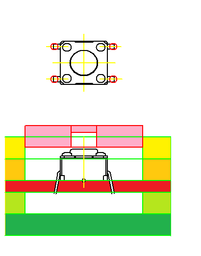
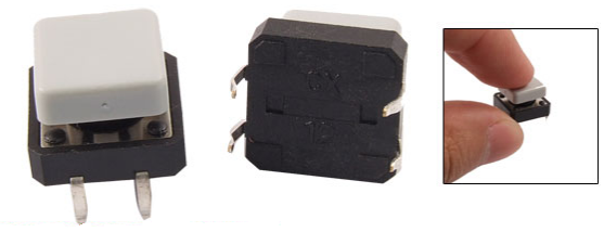
I have made a preliminary design using standard momentary contact switches (the OMRON 6 mm x 6 mm type with a 2.3 mm shaft). It would fit between 3 mm plywood sheets as shown here:
![]()
The pink cap would be 3 mm plywood as well (engraved with the symbol on the top and drilled on the bottom for press fit).
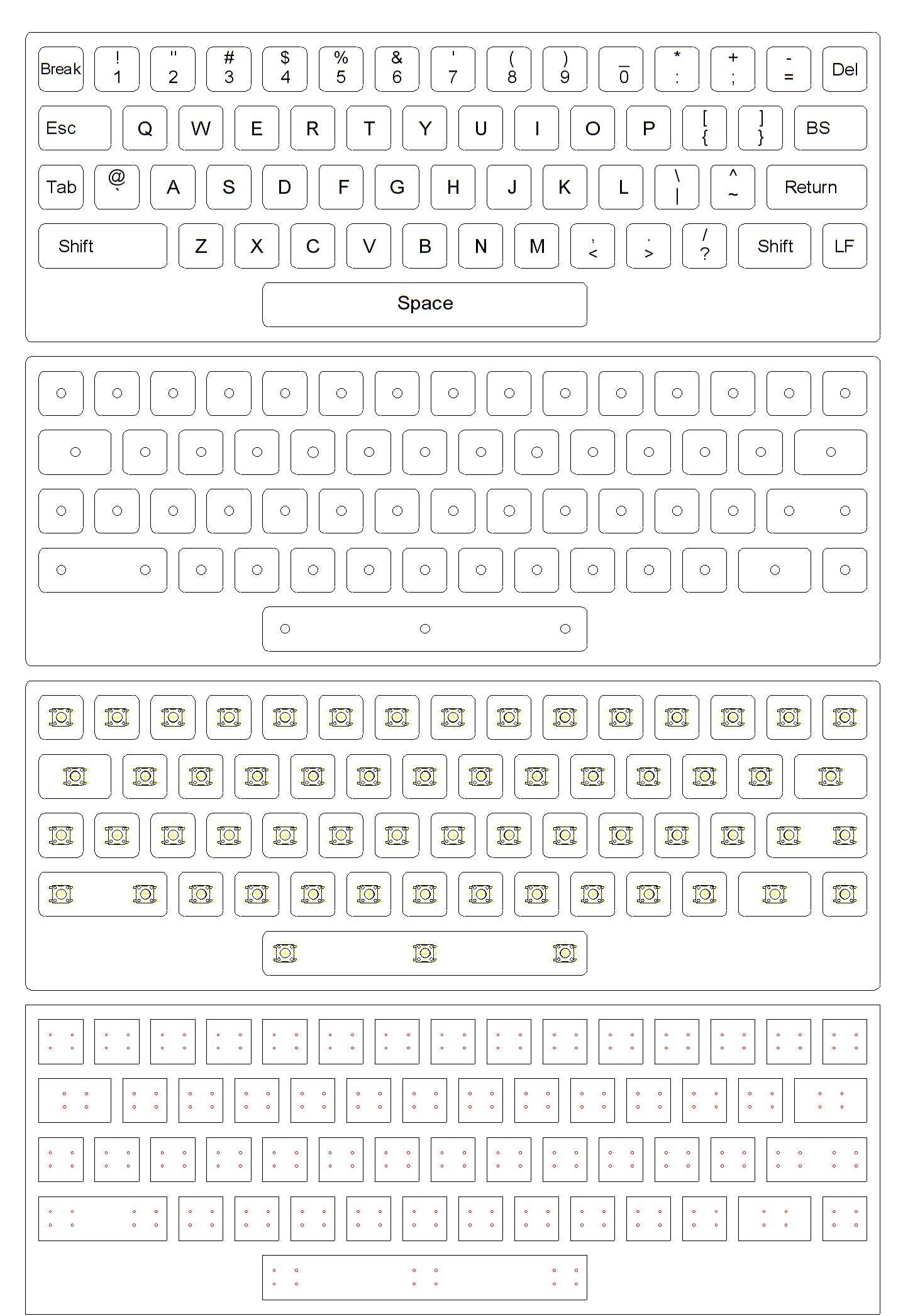
The preliminary CNC design is presented here:
![]()
A preliminary PCB
Here is the preliminary PCB:
![]()
The preliminary PCB does not include any the logic components. Looking at this board, all the electronics should me moved to the top of the PCB.
I am considering the use of these switches (12 mm x 12 mm) as they have a cap built in:
![]()
I should be able to engrave (CNC) the symbols and perhaps fill with black ink the engraving strokes directly on the cap. Alternatively a laser engraver may work here.
AlanX
-
Remapping the Keyboard
08/17/2016 at 05:05 • 0 commentsRemapping the Keyboard
Given most of the work is done with the "basic shift logic" how hard could it be?
The basic shift logic:
![]()
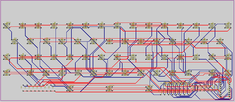
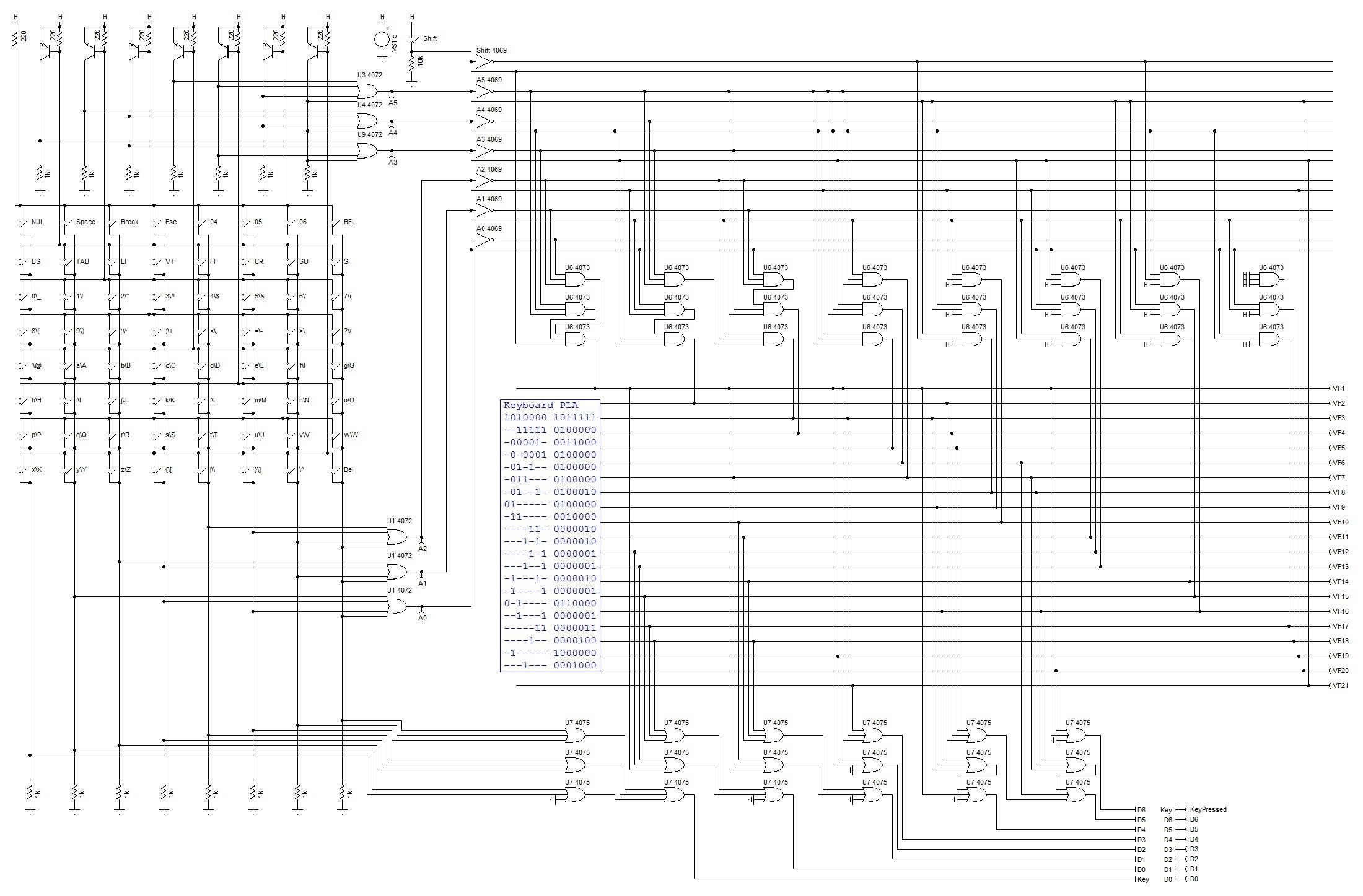
Well much harder than expected, here is the schematic:
![]()
Now many will recognise this as a PLA (Programmable Logic Array).
Designing a PLA
The first step is to generate a truth table. The problem is this is not that simple. It gets pretty confusing with 128 cases to consider.
Really the first step is to write a program to generate the truth table. So here is a simple C code program that creates the truth table:
#include <stdlib.h>
#include <stdio.h>
#include <stdbool.h>

int main(void) {

  FILE *F1;
  int a,x;
  int a0,a1,a2,a3,a4,a5,a6;
  int x0,x1,x2,x3,x4,x5,x6;

  F1=fopen("KeyBoardMapping.txt","w");
  fprintf(F1,"a0,a1,a2,a3,a4,a5,shift,,x0,x1,x2,x3,x4,x5,x6\n");
  for (a=0;a<127;a++) {
    // Shift mapping
    x=a;
    if ((a>=32)&&(a<=63)) x=a+64;  // lower case "'" to "Del"
    if ((a>=16)&&(a<=31)) x=a+16;  // Keys "0" to "?"
    if ((a>=0)&&(a<=15)) x=a;      // Ctrl keys as is
    if ((a>=96)&&(a<=127)) x=a-32; // Shift: Upper case "@" to "_"
    if ((a>=80)&&(a<=95)) x=a-48;  // Keys "Space" to "/"
    if ((a>=0)&&(a<=15)) x=a-64;   // Shift: Ctrl keys as is
    // Special key mapping
    if (x==95) x=127; // "_" is now "Del"
    if (x==32) x=95;  // "Shift 0" is now "_"
    if (x==1) x=32;   // key 0 is "Space"
    if (x==2) x=24;   // "Can" or Break/^C
    if (x==3) x=27;   // "Esc"
    a0=a&0x01;
    a1=(a>>1)&0x01;
    a2=(a>>2)&0x01;
    a3=(a>>3)&0x01;
    a4=(a>>4)&0x01;
    a5=(a>>5)&0x01;
    a6=(a>>6)&0x01;
    x0=x&0x01;
    x1=(x>>1)&0x01;
    x2=(x>>2)&0x01;
    x3=(x>>3)&0x01;
    x4=(x>>4)&0x01;
    x5=(x>>5)&0x01;
    x6=(x>>6)&0x01;
    fprintf(F1,"%d,%d,%d,%d,%d,%d,%d,,%d,%d,%d,%d,%d,%d,%d\n",a0,a1,a2,a3,a4,a5,a6,x0,x1,x2,x3,x4,x5,x6);
  }
  fclose(F1);
  return(0);
}
Once we have a truth table we determine the Prime Indicants (PIs). I use Logic Friday:
![]()
LogicFriday is a front end for Espresso by Richard Rudell (rudell@ic.Berkeley.EDU).
Here are the PIs table used to design the PLA:
![]()
So I was not wrong in saying that remapping a few keys is expensive.
(Now I did try adding the PLA after the "basic shift logic" but the result were just as bad.)
Interface
The keyboard interface pretty basic, a byte with the D7 (Key Pressed) used for polling or an interrupt.
Limitations
Note the missing Ctrl and Alt keys. So it will be up the the program to set how extended key codes are entered.
AlanX
-
Keyboard Remapping
08/17/2016 at 02:54 • 0 commentsOnly 64 Keys
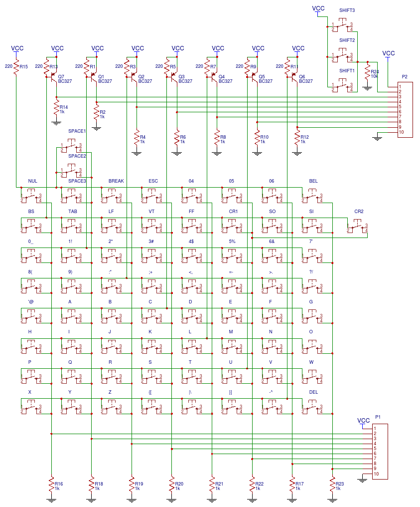
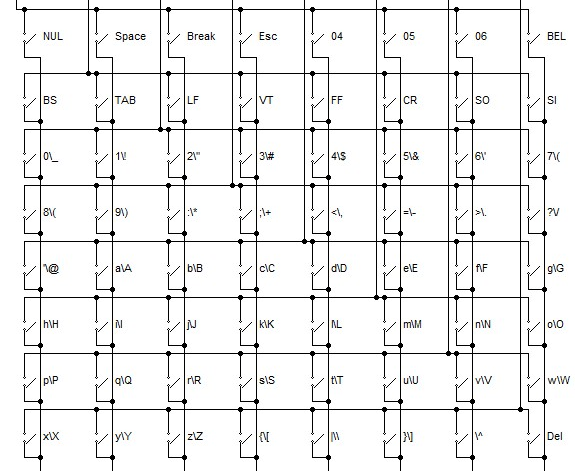
To start I have assumed only 64 keys (maximum) are available for the keyboard. The first key is mapped as code as 0, the last key as code 63. Here is my keyboard switch schematic with the final key mappings (n.b. keys 04, 05 and 06 will not be used):
![]()
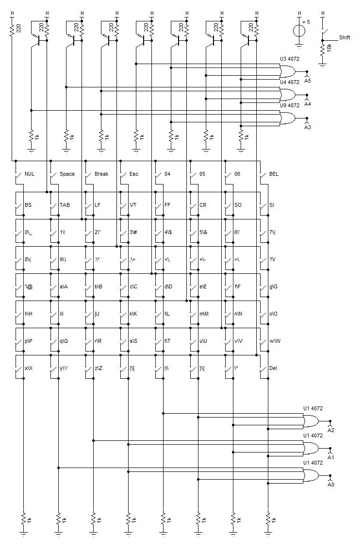
Extracting a code from the switches without column and row scanning (which is why a microprocessor is usually used) requires some analog to digital logic (the PNP transistors in the schematic):
![]()
This is the basic keyboard schematic that will map the the key code (not the ASCII code).
The column codes are A0-2 and the row codes are A3-5.
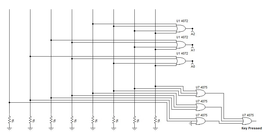
As I am using key code "0" I need to know that a key has been pressed, this logic is added to test if a key is pressed:
![]()
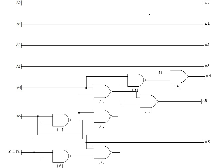
Remapping keys and the Shift Key
We need to add "shift key logic" to remap the key code to ASCII codes, and to map the lower case or shift upper case logic to the keyboard.
Here is an example of decoding logic ("the basic shift") that could be used to remap keyboard codes to ASCII codes:
![]()
Problems with the Basic Shift
The basic key shift does 95% of the work needed for a practical keyboard but there are problems:
- the space (" ") is accessed by shifting "0"
- the "DEL" is shift "_"
- the "ESC" and "CAN" (i.e. Break) are not accessible.
We therefore need to remap some individual key codes around.
Remapping individual keys is expensive.
AlanX