 Jakob Wulfkind
-
SUCCESS!
06/12/2014 at 07:43 • 0 commentsIt took a little bit of work, but I finally got a video of the driver in action. It's low quality, and the burn wasn't as clean as the one I did before I started recording, and I managed to burn my fingers at the end of the filming, but at least I managed to get it going.
You'll notice that the oscilloscope in the background keeps displaying a sawtooth wave whenever the electrodes are making contact. The rising parts of the wave are the charging pattern from the bench power supply (for safety reasons, I couldn't run the unit from wall current while it was hooked to the oscilloscope), and the falling periods are the discharge from the capacitors to the workpiece.https://www.dropbox.com/s/tr4c1mc2wbt4wei/2014-06-11%2018.02.58.jpg
I also have a few pictures of the equipment to show you:
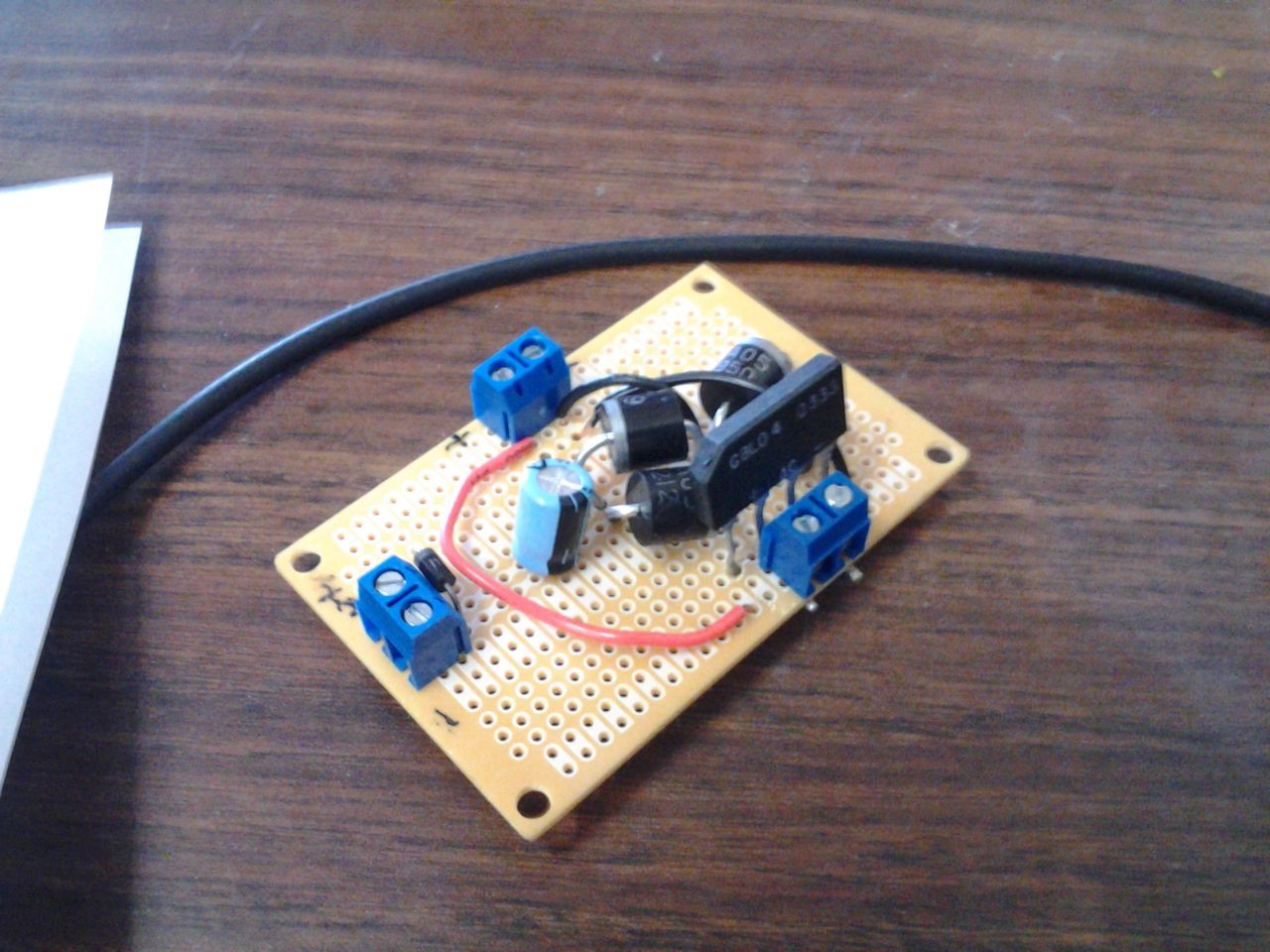
*The power supply board, freshly soldered and ready to go![]()
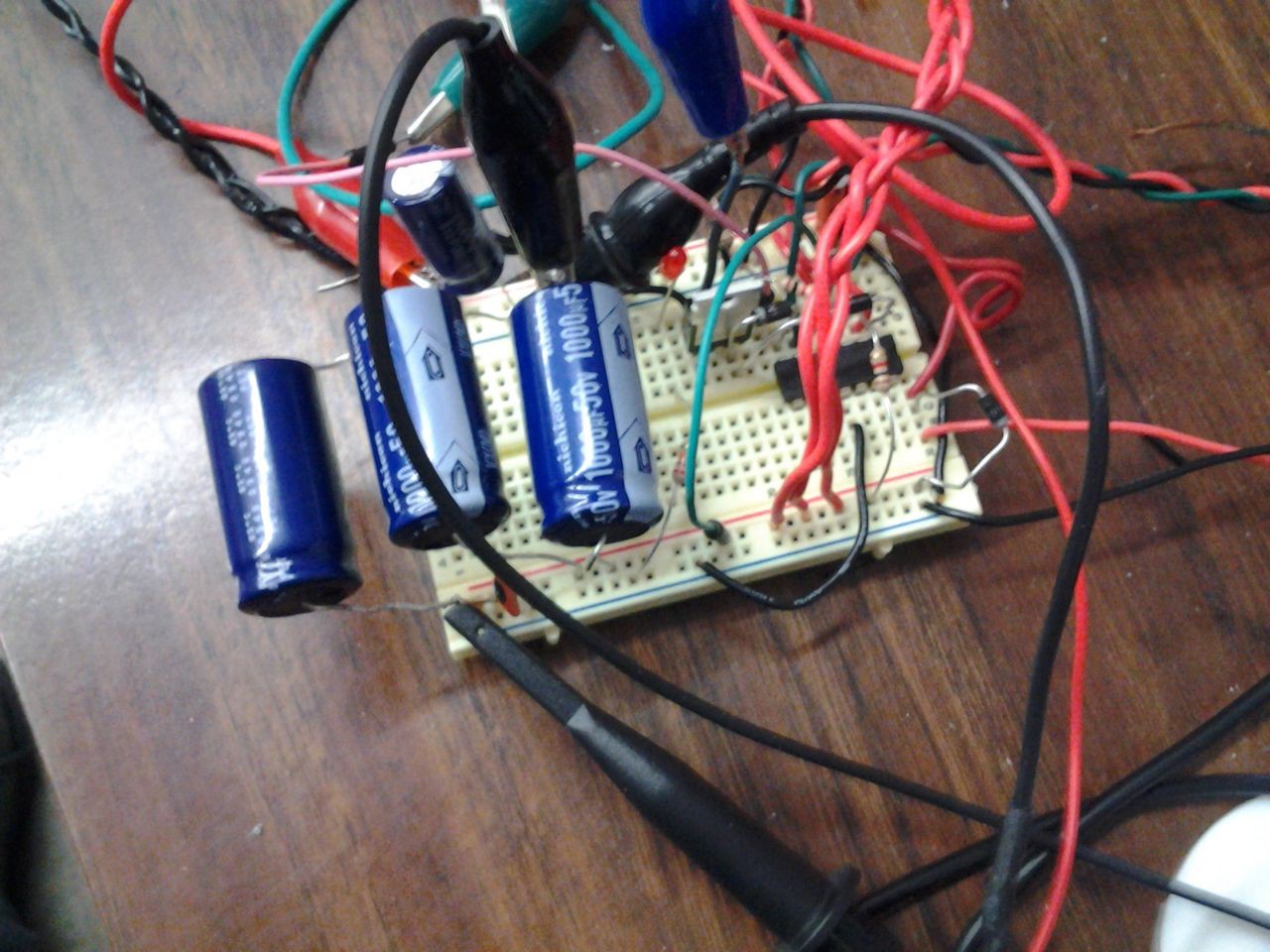
The logic board and capacitors, on a solderless breadboard.
![]()
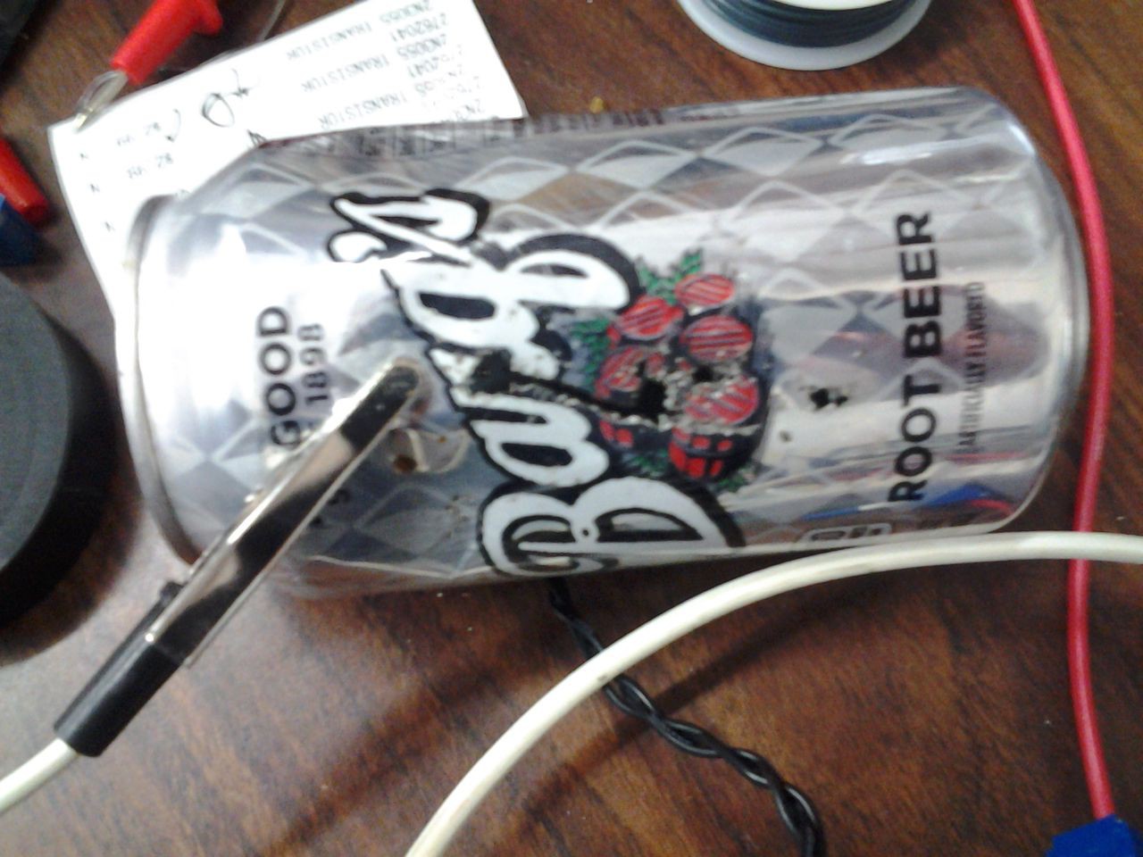
The soda can I plasma-cut before attempting a video -- it took three seconds to make that hole!. Apparently this circuit is camera shy.
![]()
The soda can I cut in the video. I realized after I finished the video that I didn't properly sand away the insulative enamel on the outside of the can, so that's probably why it took me so long to strike a proper arc and cut all the way through.
![]()
More soon!
-
In Which Actual Circuit Diagrams are Shown
06/07/2014 at 18:51 • 0 commentsSo apparently the habit that I am actually in is promising myself that I will post a project log every wednesday, and then posting a log a few days late.
Working on this project has taken me fairly far from my existing experience with low-power electronics into the realm of high-current devices. About once every few hours, I get a reminder of this in the form of a jumper wire, diode, or capacitor overheating and going up in a puff of smoke and having to be replaced with a thicker, more robust version. This also seems to be the reason why I haven't already generated anything more powerful than a bright spark -- I was originally using twenty-gauge wire as my discharge electrode leads, and the wires themselves were the source of so much resistance that they significantly reduced the output power. It's an odd change from small-signal electronics to actually have to worry about half an ohm.Because of the high wattages and discharge currents involved, I've separated the project into three portions: the capacitor bank, with its own dedicated rectifiers, the logic board, with a separately rectified VCC (ground is still common), and the power supply board that provides these rectified voltages from the transformer. The power supply board is fairly straightforward:
![]()
D1-D4 are high-amperage discrete rectifier diodes, while B1 is a standard integrated bridge rectifier.
![]()
The capacitor board should be separated by a little bit of distance from the other two boards, as a leaky capacitor (or, as shown in the last log, an exploding one) can put the other components at risk.
![]()
With the relay open, cap_charge will increase until it reaches the threshold voltage set by DISCH_VOLTAGE, and will then trigger Q1 to close the relay on the capacitor board and allow power to flow through the electrodes. This will also charge the ELECTRODE_VOLTAGE line, allowing the second comparator to hold the relay closed until it drops below the voltage set by the PULSE_LENGTH potentiometer. This allows a user to set the desired discharge voltage, and the total percentage of the capacitor's power discharged by a single pulse, which will in turn control how long the capacitor bank takes to recharge and initiate another pulse.
-
Ker-ZOT!
06/03/2014 at 17:46 • 0 commentsSo I haven't been keeping up with my planned once-a-week project log schedule, and there's a lot of development that's already gone on. Here it is in a nutshell:
This build started two weeks ago while I was waiting on the CNC machine to become available for my other project, the hybrid axis wind turbine (I also haven't been posting logs there as diligently as I should have. Suffice to say there has been progress there as well). I had been thinking about mounting solutions for the wind turbine, specifically concentrating on steel lattice support structures, and decided to try making a quick-and-dirty capacitive arc discharge welder out of a few supercapacitors lying around in the lab.
The old standby of charging a cap for a few seconds and then using it to melt a hole in the side of a coke can was well and good, but the novelty wore off quickly, and it was clear that I wouldn't be able to use that method to create durable structures . Also, I made the discovery that you shouldn't use a plasma discharge arc on a soda can that hasn't been opened.
It occurred to me that by manually charging and discharging the cap, I was in essence using a very primitive form of PWM. I then realized that if I could automate the system to charge to a particular voltage, then discharge until it dropped down below a threshold voltage, that the size of the capacitors wouldn't matter, since I would be outputting the same wattage over a long enough time. I switched from a 3.1F audio capacitor to four 1000 uF capacitors.
![]()
...I'm now down to three 1000 uF capacitors. Kids, always remember to check the polarities when wiring a high-wattage circuit.
But the concept was a sound one! I got just as much sparking and pitting from 3000 microfarads on an automated charge-discharge cycle as I did with 3 Farads discharging by hand! I don't have any photos, unfortunately (it really isn't safe to be handling a high-wattage system with one hand and photographing it with the other), but I expect to have a few posted on my next build log.
Pulsed Capacitive Discharge Power Supply
Pulsed-discharge power system suitable for welding, plasma cutting, laser driving, and other high-power equipment.


