-
BOM
07/18/2017 at 20:57 • 0 commentsSince the components list here on Hackaday.io is a horrendous way to publish a BOM and a BOM needs to be published for projects entering the "Best Product" Hackaday Prize category, I decided to upload a spreadsheet instead. :) I also tested the FindChips software Hackaday was pushing, and it's pretty cool, but I didn't get much support to add components it didn't know about. Anyway, here's also a link to that BOM. Enjoy!
-
For sale on Tindie!
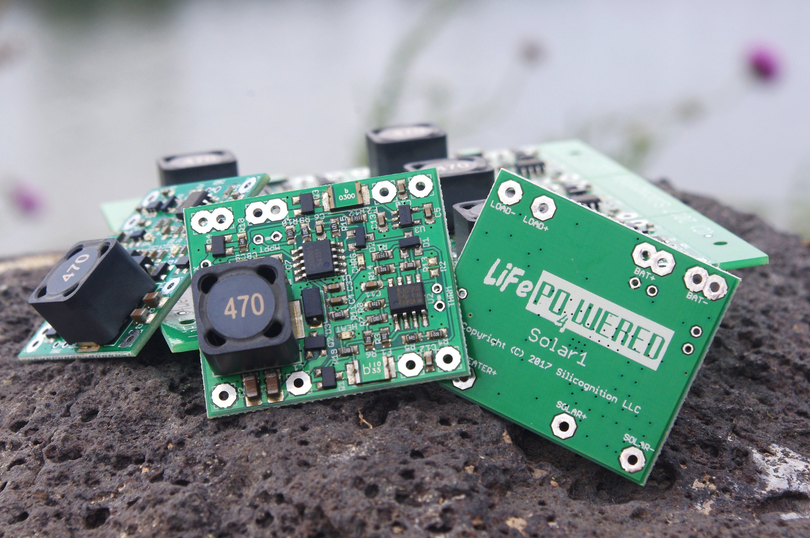
06/29/2017 at 17:04 • 0 commentsFinally got around to taking some product pictures and writing enough documentation to be able to start selling the prototypes I built on Tindie!
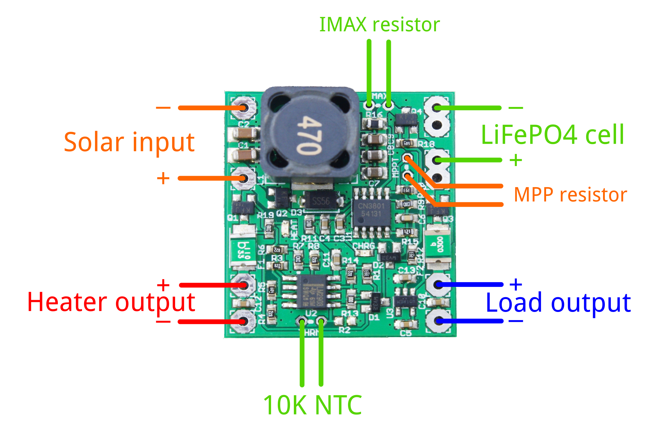
Hopefully with the connection diagram and design information it will be possible for most people with some electronics background to use these successfully.
I'll duplicate some of this information here for those interested in how to make use of this board:
![]()
Calculating MPP resistor
To extract the maximum amount of power from your solar panel, you need to customize the maximum power point setting to match that of your panel. Use the following formula to calculate the value of the MPPT resistor:
MPPT = 120500 / (Vmpp - 4.295)
Some examples values from my own testing with different panels:
- 6V panel, Vmpp = ~5.2 V -> MPPT = 120K
- 9V panel, Vmpp = ~8V -> MPPT = 33K
- 18V panel, Vmpp = ~16.2V -> MPPT = 10K
Customizing maximum charge current
There are many ways that charge current is limited by different parts of the system, so often it's not necessary to worry about limiting the maximum charge current. For instance, even in the brightest sun, the output power of the solar panel may be limited to the extend that the charge current never reaches the limit of the battery. You can check this by taking the wattage of the panel, and using it to calculate the theoretically maximum charge current (Icharge = Ppanel / 3V).
If you find you do need to limit the current, you can calculate the maximum current as follows:
Ichargemax = 0.12 / Rsense
Rsense for different default charge current versions I have for sale:
- 3.07A: 0.039 ohm
- 2.35A: 0.051 ohm
- 1.93A: 0.062 ohm
- 0.5A: 0.24 ohm
The maximum charge current can be increased by adding a resistor IMAX in parallel with the sense resistor already present on the PCB. The new sense resistance can be calculated by:
Rsense = Rdefaultsense * IMAX / (Rdefaultsense + IMAX)
You can then use this new Rsense value to calculate the resulting charge current limit.
Thermistor
A 10K NTC thermistor needs to be connected for the system to operate correctly. The system has been designed for thermistors with a B value of 3950, but reasonable performance can be had for B values down to 3435. There is a footprint for surface mount (R2) as well as through hole (THRM) thermistors. Only one of them should be used at a time.
Many battery packs come with a 10K thermistor built-in, and connecting this thermistor to the charger is the ideal situation. If no thermistor is present in the battery pack, we sell a thermistor with 8 cm leads that can be taped to the battery pack. A surface mount thermistor on R2 may work if there is little temperature difference between the PCB and the battery. If you don't want thermal protection of any kind, a 10K resistor can be installed instead of a thermistor.
Below are calculated threshold levels for different B values of the thermistor:
- [B value 3950] Under temp limit: 0.2°C (falling), 0.7°C (rising) - Over temp limit: 52°C (falling), 58°C (rising)
- [B value 3435] Under temp limit: -3.2°C (falling), -2.6°C (rising) - Over temp limit: 57°C (falling), 64°C (rising)
Battery heater
In under temperature conditions, the solar panel's voltage is applied to an optional heater connected to the HEATER pads. This can be used to bring the battery up to temperature before charging is started, ensuring that no low temperature lithium plating occurs and thus maximizing battery life.
In its simplest form, the heater can be a power resistor thermally connected to the battery pack. Since no MPP is maintained, the user needs to take care to choose the resistor value so it will not collapse the solar panel voltage under reasonable light conditions where enough energy is present for heating, while at the same time ensuring it doesn't pull more than 1.1A under ideal light conditions.
Limitations
- Does NOT come with a battery, this one is BYOB (Bring Your Own Battery).
- ONLY use LiFePO4 batteries, no other Li-ion or LiPo!
- Only use a single cell 3.2V LiFePO4 cell, or place cells in parallel to create a larger capacity LiFePO4 battery that still has 3.2V output voltage. Cells in series are NOT supported.
- The load output has a 3A thermal fuse, the heater output a 1.1A thermal fuse.
- If you don't connect an MPP resistor, the MPP voltage will be 4.295V. Unless you have a 5V solar panel, you will not extract energy from the panel efficiently.
- If you don't connect a thermistor, the system will be in under temperature protection.
- Don't trust your solar panel spec, it is likely highly overrated. Do your own testing to find maximum power output and maximum power point voltage. In reality you can expect about 70% of rated power.
-
Pick-and-place prototype build
05/29/2017 at 19:56 • 0 commentsI received my prototype panels from Elecrow, very happy with the quality of these low cost boards I must say! So I went through the work of setting up the TinkerMill's TM245P pick-and-place machine to build prototype panels. I made a video to show part of the build process for those who are curious:
I'm building versions with different sense resistors. In principle I could produce them all with the maximum sense resistor of 0.24 ohm and then have customers add a through-hole resistor in parallel if they want a higher maximum charge current, but people don't tend to have these very low resistor values just laying around and they tend to cost more than normal resistors, so it seems to make sense to offer different values.
I will be offering 0.5A, 1.93A, 2.35A and 3.07A current limits. Note that this only configures the maximum charge current if you have a very high input source, in practice your solar panel will have a limited current output anyway and you may be able to charge a small 0.5A battery perfectly safely with a 3.07A board if your solar panel is small.
I still have to work on documentation but I hope to have these boards available in my Tindie store shortly so people can start putting these in the field. :)
-
Updates! Panel on order
04/21/2017 at 23:57 • 2 commentsI decided to use the Hackaday Prize 2017 as motivation to try and finally push this project to production! :)
I've had a unit outdoors in my #SoundBeacon project through the Colorado winter. We didn't have a very severe winter, so it wasn't a great test, but it seemed to work fine. I never saw the battery voltage go below 3.2V.
I've incorporated some changes based on what I've learned from testing the #LiFePO4wered/18650. I've gone to a bigger, higher current Schottky diode, and a newer, higher current MOSFET that I also intend to use in the #LiFePO4wered/Pi+. I hope to streamline my operations by trying to standardize components across projects. I also added a lot of thermal vias near the power components, especially the Schottky diode, to pull heat to the ground plane. With these changes, I hope that the system will be capable of 3A charge and load currents. To accommodate this, I also changed the thermal fuse on the output. The updated schematic is available in the files section.
If I did all my calculations correctly, the thermal protection system should be able to work with 10K NTC thermistors with B value between 3450 and 3950 (this seems to be some sort of "standard" in battery packs... I wish they'd ACTUALLY pick a standard resistance and B value instead). The battery will stop charging and the heater will kick in when the temperature falls below -3.1 to 0.2 degrees C. Charging will resume when the temperature rises above -2.5 to 0.7 degrees C. On the high temperature end, charging will stop when the temperature goes above 58 to 63 degrees C and will resume when the temperature falls below 52 to 57 degrees C.
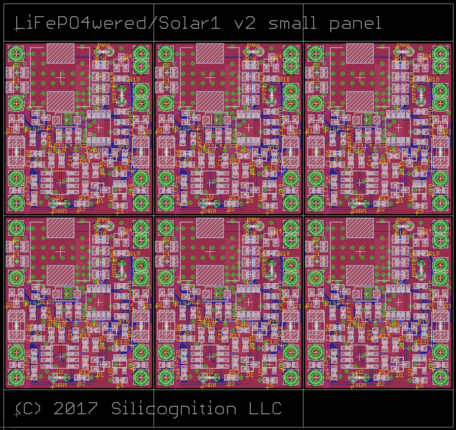
I decided I need to get many more prototypes into the field to build confidence in the system. So I designed a panel so I can build a good number:
![]()
It's a small panel designed to fit within the 10x10 cm limits of Elecrow's Special Offer. So I will be getting 10 panels of 6 PCBs and I intend to use Tinkermill's TM245P pick-and-place machine to build these myself, since there are no difficult, small pitch components.
They are not officially for sale, but I had one customer very helpfully offer to buy some (at reduced "prototype" price) and test them in his devices. Thanks much Will! I want to encourage anyone else who has a need for a solar power supply to do so as well. The more field test data I can collect, the better!
-
Schematic!
11/17/2016 at 19:01 • 0 commentsI've added a PDF of the schematic! At this point, the main charging part is know to work, but not thoroughly tested over the full voltage and temperature range. The over and under temperature protection has not been tested either, nor has the heater.
But it might be useful to someone to get an idea. :)
-
First prototype build
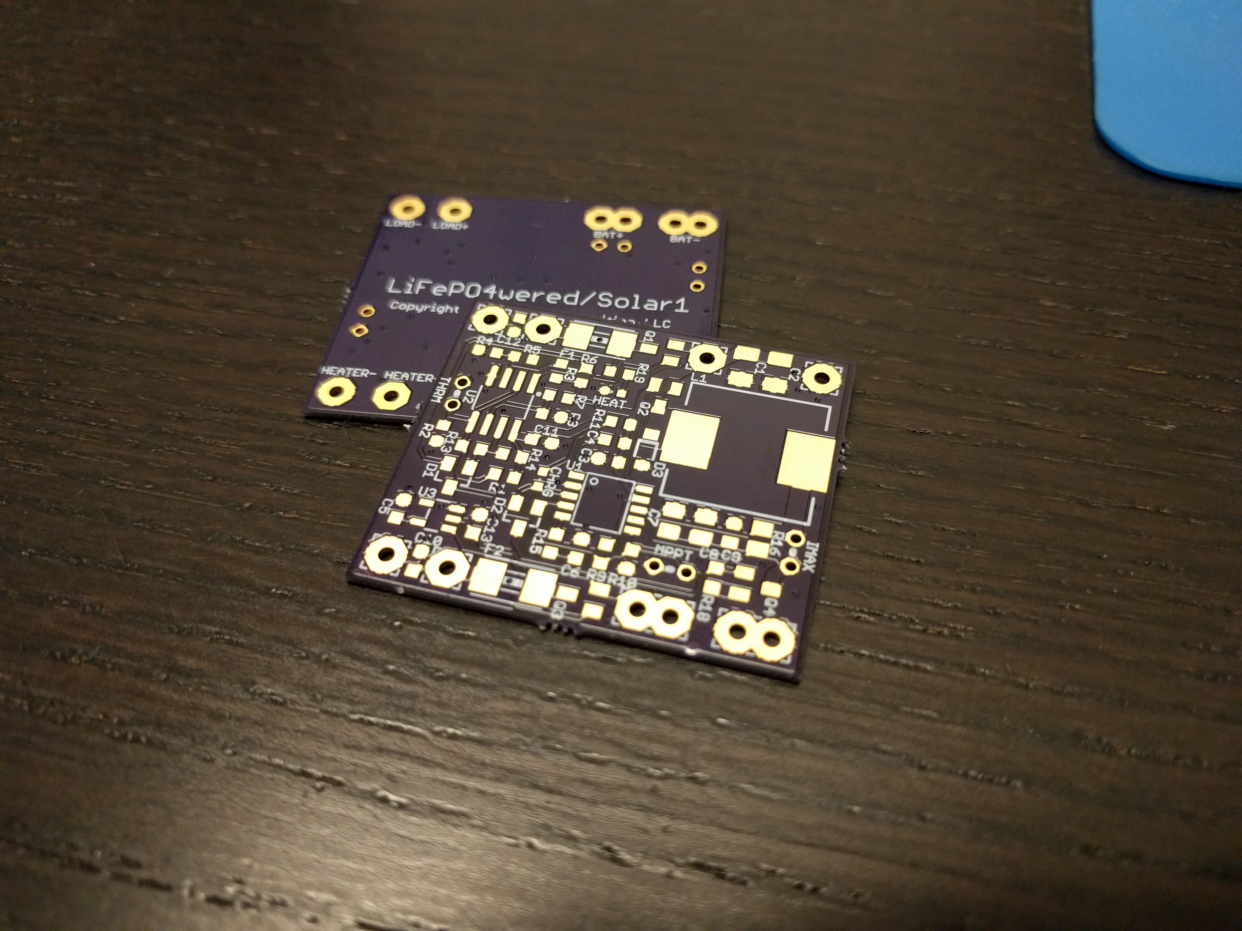
08/22/2016 at 19:41 • 1 commentReceived some perfect purple PCBs from @oshpark, so it was time to build prototypes!
![]()
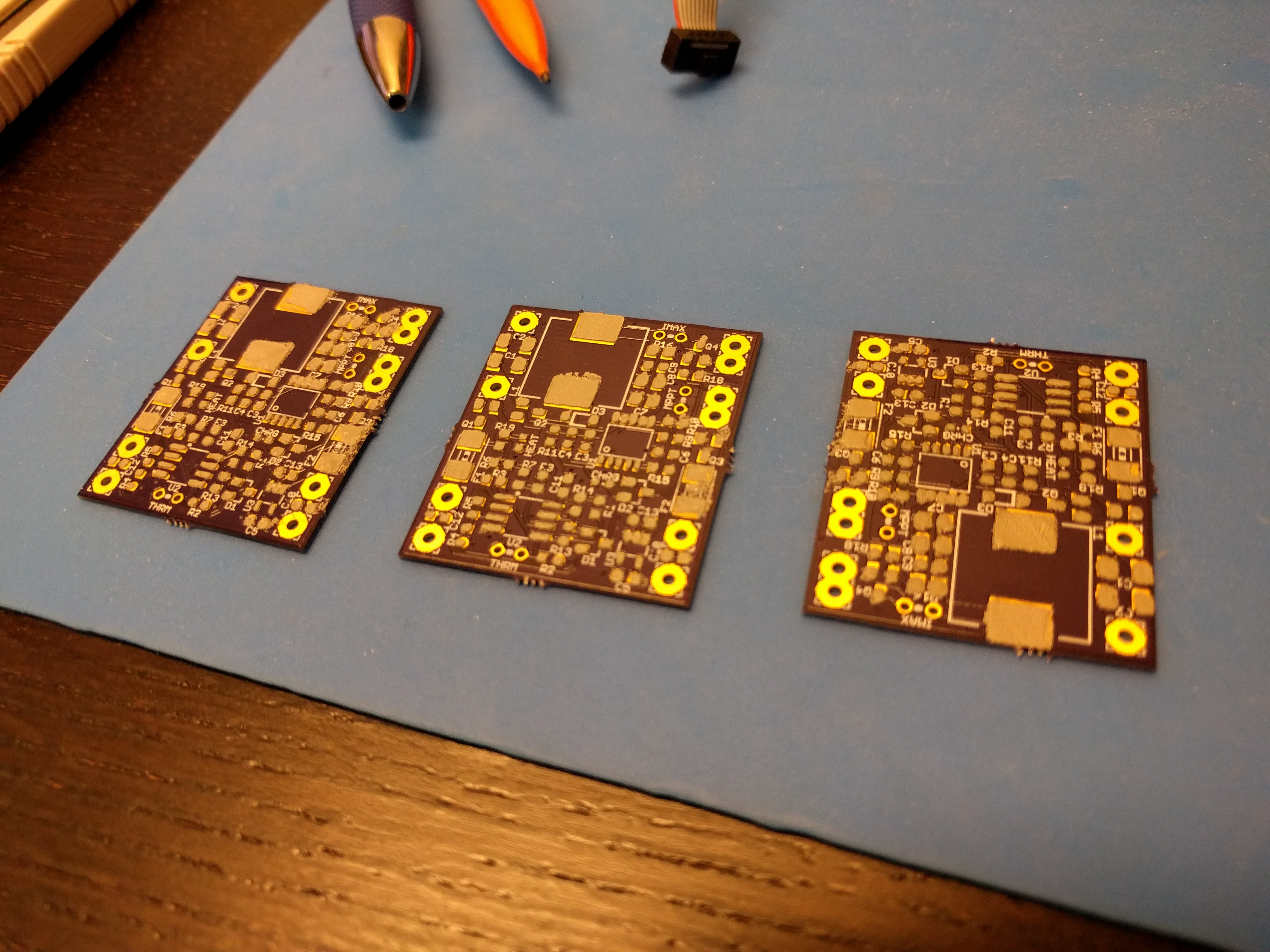
I decided to build up all three boards at once (I guess I'm an optimist), and use a stencil and solder paste, but place the parts by hand instead of using the Pick-and-Place available here at the Tinkermill. I tried to use the laser cutter to make a kapton stencil. It worked horribly, but after many tries I finally had something usable enough to make these three boards. Here are the PCBs with (fairly messy) paste applied:
![]()
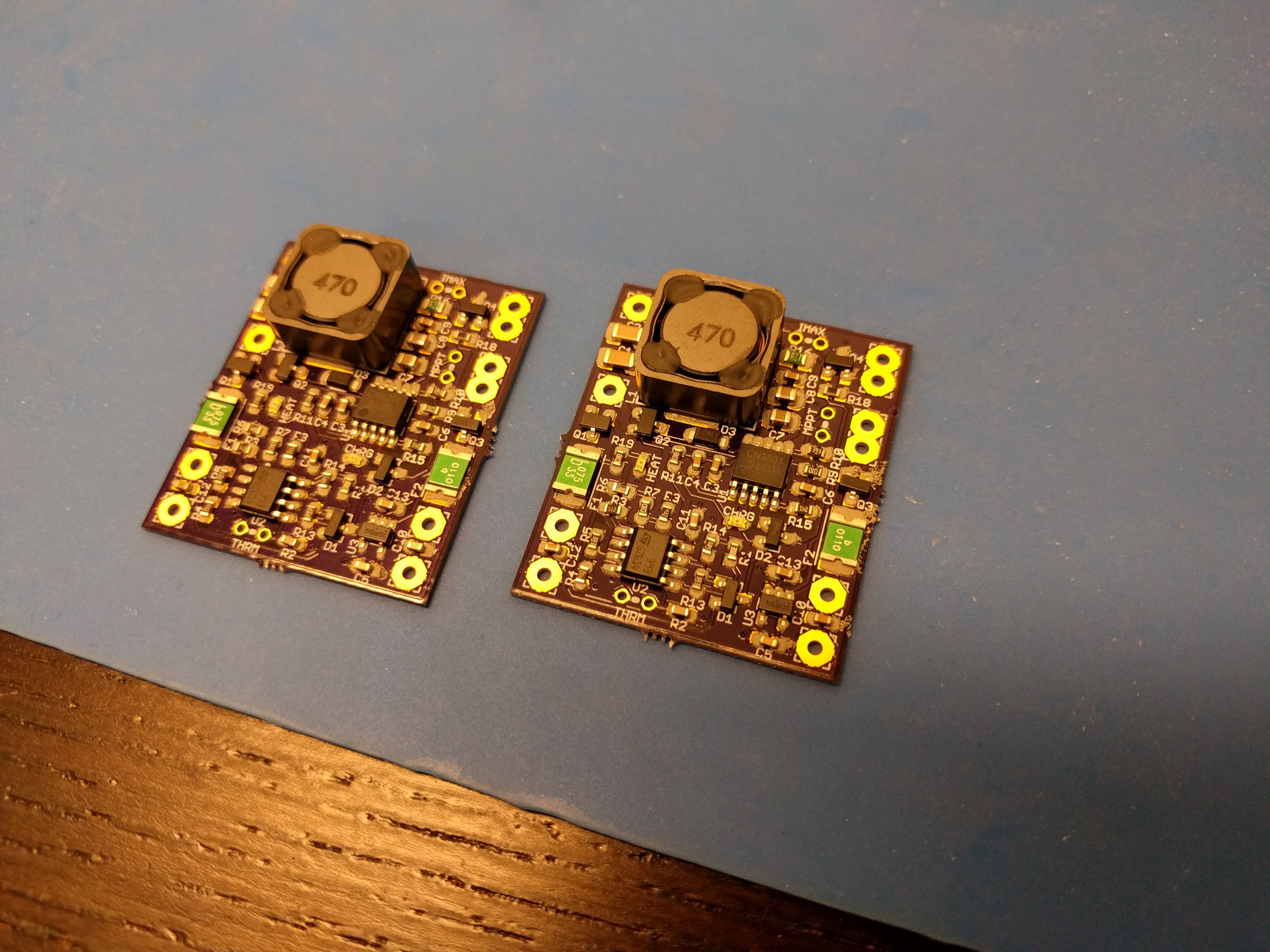
I figured the messy paste would be OK in this case since no small pitch components are involved. After spending some time placing the parts, this is how things looked:
![]()
Only two boards in the picture because the other one is in the reflow oven. :) The end result after all three boards were reflowed:
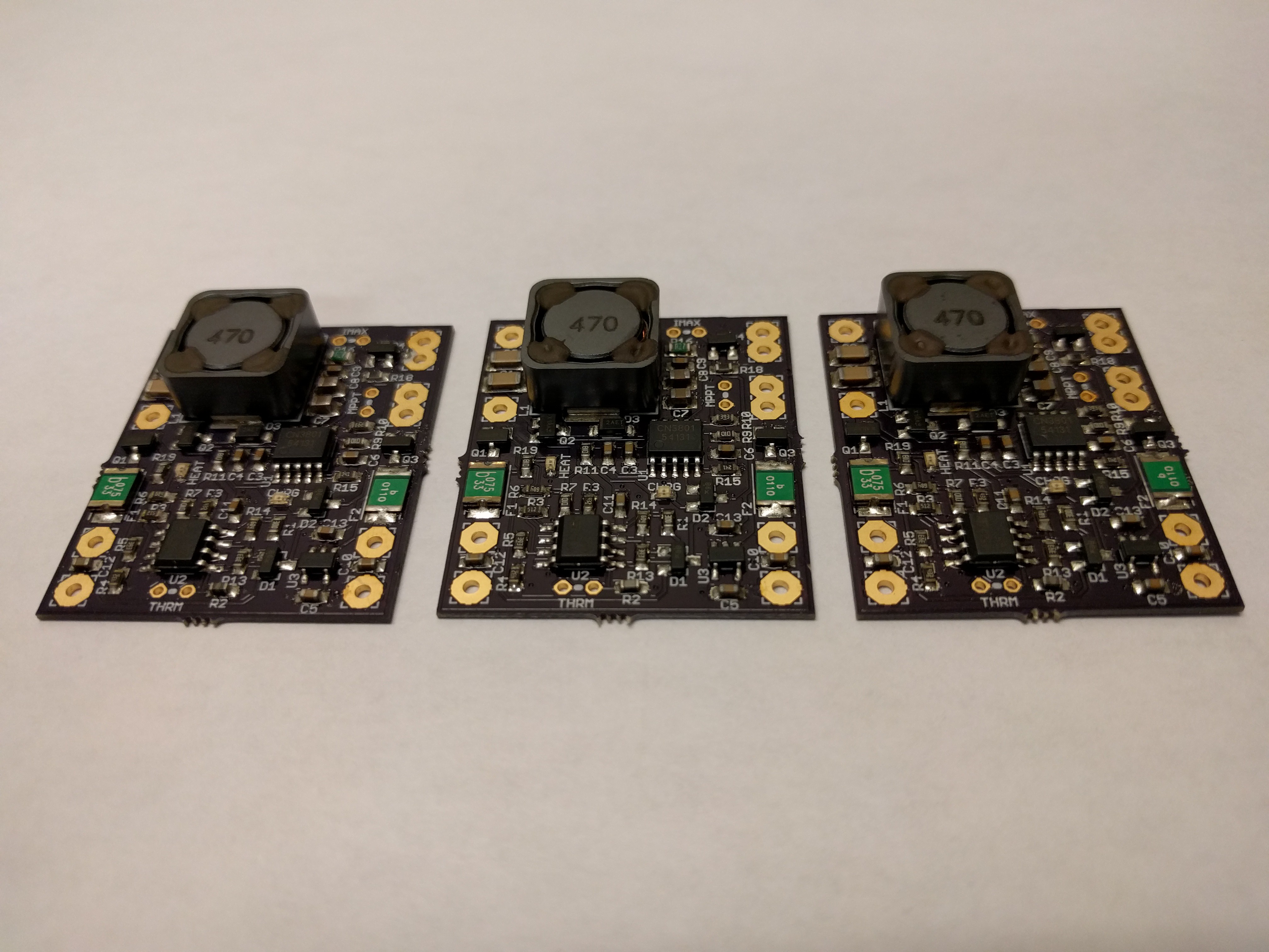
![]()
Nice, they turned out well! Next, I need to find some time for testing.
 Patrick Van Oosterwijck