deʃhipu
-
20ch Firmware Improvements
01/20/2017 at 21:25 • 0 commentsToday I spent several hours working on the firmware -- adding the address selection support and making the whole thing much robust.
The first thing I added, was to modify place where the servo events are updated. Until now, they were updated immediately after the I2C transaction finished -- as soon as we had the servo pulses. But that meant that if you are unlucky, it could happen while the timer interrupt fires, and the data seen by the interrupt would be inconsistent. We can't switch off the interrupts while updating the events, because it takes very long time, and our timings would be completely off then. So what can be done? Well, all the events typically happen in the first 2ms of the cycle. We have 18ms left to update the events (that's also why the glitch wasn't so easily visible). So now, when the I2C transaction finishes, a flag is set signalling that an update is needed. Then, while waiting for more I2C data, the loop checks that flag and whether the last event in the cycle has been already processed. As soon as the last even is processed (which we can recognize by the fact that it has delay of 0xffff), we update the events and clear the flag. Sounds easy, but it took me some hours to get right.
Unfortunately, that didn't eliminate all the glitches. The second problem happens when you have two events very close to each other -- so close, that processing of the first one finishes after the second one's scheduled time. You could expect the second event to be a bit late then, but it's actually much worse -- since the interrupts fire on equality, and not whenever the counter overflows the trigger, the interrupt for the second event is skipped entirely and never fires -- the pin is only updated in the next event, or never, if that event was the last one. Ouch. I spent some time optimizing the interrupt routine and moving stuff in it to make it a bit more robust, but it's never processed instantly, and the problem remains. In the end, I'm just looking for events that happen too soon after the previous one, and when that happens, merge them with that previous event. It introduces a few microseconds of a glitch, but that's better than the alternative.
For the address selection, I had to use the analog-only pins of the ATmegaXX8. I was already a bit tired when I started on it, so I stupidly copied the code from my #Mechatronic Ears project, forgetting that it's for an ATtiny85. And it mostly worked -- the AVR chips are very similar, after all, especially when using the correct header files with the right macros -- except that I masked wrong bits in the mux selection. It took me sever tries to track that down, but once I found it the fix was trivial.
The next bug is related to the internal pullups I'm enabling on the I2C lines. Turns out I had the masks for the PWM routines slightly wrong, and they were also toggling the pullups. The effects on the I2C transmission were... interesting, if not a bit nondeterministic. It helped that I got a really nice logic analyzer for Christmas, that also has an analog channel, and that I could see the voltage levels on the I2C lines acting weird, even when there was no data being transmitted. Fixing this while keeping the interrupt routines as fast as possible took several tries, but I managed to move all the operations into the event update routines in the end.
The last thing I added is sending a stop condition on the I2C bus whenever something unexpected happens on it. That lets me recover from errors in communication more easily.
-
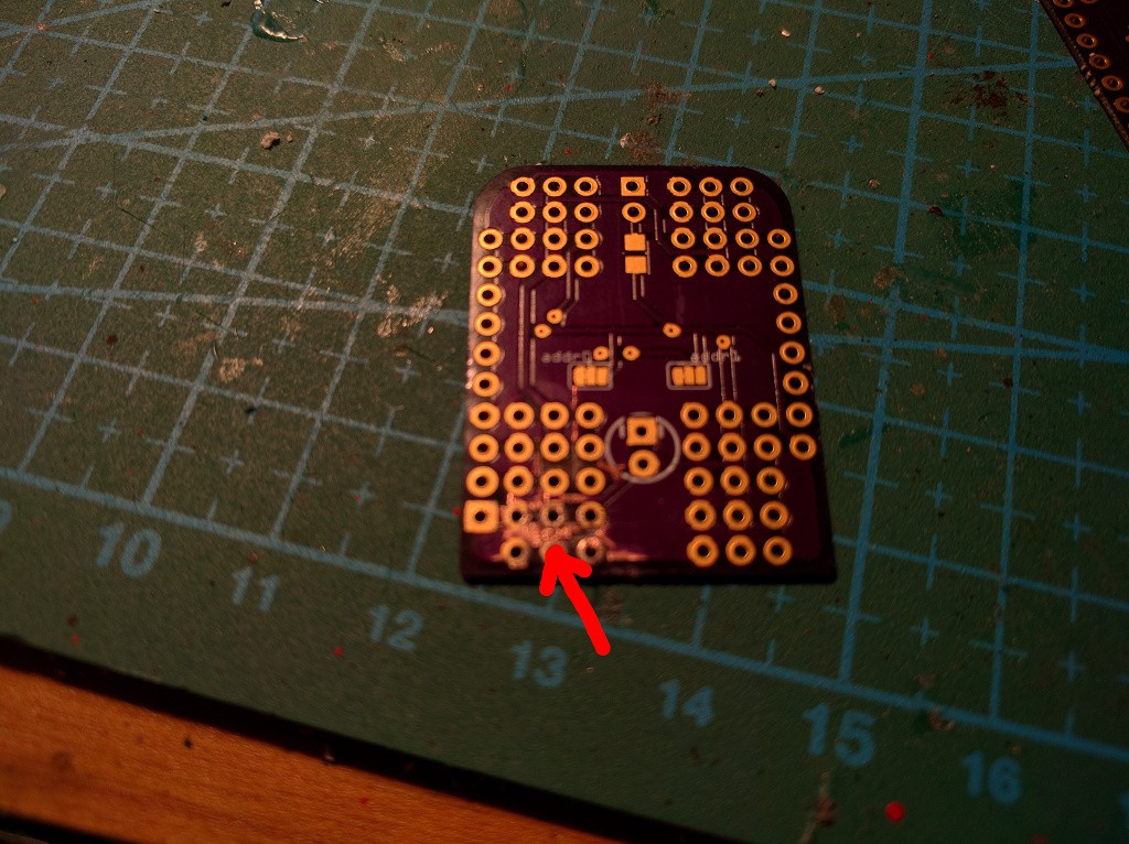
20ch Servo Shield Assembled
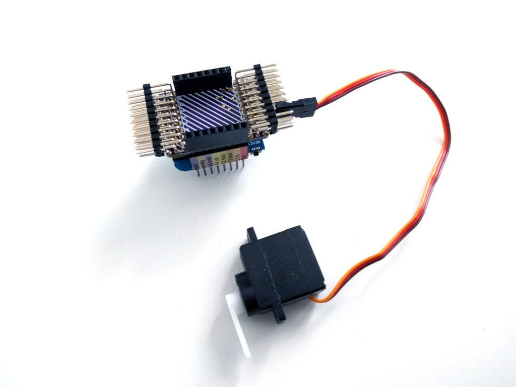
01/20/2017 at 10:13 • 0 commentsIt took some time, but the 20-channel version of the D1 Mini servo shield is finally assembled. I still used an ATmega328p, because that's what I have on hand (the code is now small enough to work on an ATmega8). As you can see on the picture below, the angled headers make it stick out of the D1 Mini outline a little bit -- but now you can really stack them! Once I update the firmware to take into account the address selection jumpers, you will be able to stack four of those babies, giving you a total of 80 servos to control. Of course powering that many servos from the poor D1 Mini is a bad idea (unless most of them only move sometimes), so you can also cut the trace connecting the 5V power with the D1 Mini pin, and provide the power separately.
![]()
Of course, as soon as I got the PCB in my hands, I immediately got some ideas on how to improve it: connect the reset pin to the D1 Mini's reset pin, for easier programming and to make them both reset together, make the D1 Mini outline on the top of the board smaller, so it's more readable, etc. -- but those are small things, and I'm mostly happy with this version.
-
Firmware for the 20-servo Shield
12/19/2016 at 09:16 • 0 commentsIt took some work, and it took some compromises. I ended up not using the first trick I mentioned, of sending the signals for each port separately. I also ended up needing sorting anyways, but did that with a horrible O(n²) insertion sort -- anything to save some bytes. But it's here and it works. I even managed to squeeze in an array for remapping the channel numbers to what is actually written on the shield. The whole thing has 990 bytes and you can see it below, or in this repository: https://bitbucket.org/thesheep/d1-mini-20ch-servo/src
#include <avr/io.h>
#include <avr/interrupt.h>
#include <inttypes.h>


#define I2C_ADDRESS 0x10
#define I2C_BUFFER_SIZE 32


static unsigned char i2c_buffer[I2C_BUFFER_SIZE];
static unsigned char i2c_cursor;
static union {
    unsigned char bytes[2];
    unsigned int value;
} bytes2int;


#define MAX_SERVO 20

static uint16_t servo_pulse[MAX_SERVO];

volatile static uint16_t servo_delay[MAX_SERVO + 1];
volatile static uint8_t servo_mask_b[MAX_SERVO];
volatile static uint8_t servo_mask_c[MAX_SERVO];
volatile static uint8_t servo_mask_d[MAX_SERVO];
volatile static uint8_t servo_event;

// Remap servo numbers to pins.
// 0 = PB0  1 = PB1  2 = PB2  3 = PB3  4 = PB4  5 = PB5  6 = PB6 7 = PB7
// 8 = PC0  9 = PC1  10 = PC2  11 = PC3  12 = PD0 13 = PD1  14 = PD2  15 = PD3
// 16 = PD4  17 = PD5  18 = PD6 19 = PD7
const static uint8_t servo_map[MAX_SERVO] = {
    13, 10, 11, 12, 14, 15, 16, 6, 7, 17, 9, 8, 5, 4, 3, 2, 1, 0, 19, 18
};

ISR(TIMER1_COMPA_vect) {
    servo_event = 0;
    PORTB = 0b11111111;
    PORTC = 0b00001111; // leave out RESET, SDA, SCL, PC7
    PORTD = 0b11111111;
    TCNT1 = 0;
    OCR1B = servo_delay[0];
}


ISR(TIMER1_COMPB_vect) {
    PORTB &= servo_mask_b[servo_event];
    PORTC &= servo_mask_c[servo_event];
    PORTD &= servo_mask_d[servo_event];
    servo_event += 1;
    OCR1B = servo_delay[servo_event];
}


void servo_update() {
    uint16_t last_pulse = 0;
    for (uint8_t event = 0; event < 8; ++event) {
        uint16_t smallest_pulse = 0xffff;
        for (uint8_t servo = 0; servo < MAX_SERVO; ++servo) {
            if (servo_pulse[servo] > last_pulse &&
                servo_pulse[servo] < smallest_pulse) {
                    smallest_pulse = servo_pulse[servo];
            }
        }
        servo_delay[event] = smallest_pulse;
        servo_mask_b[event] = 0xff;
        for (uint8_t servo = 0; servo < 8; ++servo) {
            if (servo_pulse[servo] <= smallest_pulse) {
                servo_mask_b[event] &= ~(1 << servo);
            }
        }
        servo_mask_c[event] = 0xff;
        for (uint8_t servo = 0; servo < 4; ++servo) {
            if (servo_pulse[8 + servo] <= smallest_pulse) {
                servo_mask_c[event] &= ~(1 << servo);
            }
        }
        servo_mask_d[event] = 0xff;
        for (uint8_t servo = 0; servo < 8; ++servo) {
            if (servo_pulse[12 + servo] <= smallest_pulse) {
                servo_mask_d[event] &= ~(1 << servo);
            }
        }
        last_pulse = smallest_pulse;
    }
}


int main() {
    // setup i2c slave
    PORTC |= 1<<PC4 | 1<<PC5; // enable pullups
    TWAR = I2C_ADDRESS<<1;

    // setup servos
    TCCR1A = 0x00;
    TCCR1B &= ~(1<<CS12 | 1<<CS11 | 1<<CS10);
    TCCR1B = 0x02; // prescaler 8
    OCR1A = 20000; // period
    TIMSK1 = 1<<OCIE1A | 1<<OCIE1B;
    DDRB = 0xff;
    DDRC = 0x0f;
    DDRD = 0xff;
    for (int i = 0; i < MAX_SERVO; ++i) {
        servo_pulse[i] = 0;
        servo_delay[i] = 0xffff;
    }
    servo_delay[MAX_SERVO] = 0xffff;
    servo_update();
    sei();
    TCCR1C |= 1<<FOC1A; // trigger COMPA

    // run i2c slave
    while (1) {
        TWCR = 1<<TWEN | 1<<TWINT | 1<<TWEA;
        while (!(TWCR & (1<<TWINT))) {}
        switch (TWSR & 0xF8) {
            case 0x60: // received address for write and acked
                i2c_cursor = 0;
                break;
            case 0x80: // received data and acked
            case 0x88: // received data and nacked
                if (i2c_cursor < I2C_BUFFER_SIZE) {
                    i2c_buffer[i2c_cursor++] = TWDR;
                }
                break;
            case 0xa0: // stop or repeated start received
                if (i2c_cursor > 0) {
                    unsigned char i2c_servo = i2c_buffer[0];
                    for (unsigned char i = 1; i < i2c_cursor - 1; i += 2) {
                        if (i2c_servo >= 20) {
                            i2c_servo = 0;
                        }
                        bytes2int.bytes[0] = i2c_buffer[i];
                        bytes2int.bytes[1] = i2c_buffer[i + 1];
                        servo_pulse[servo_map[i2c_servo]] = bytes2int.value;
                        i2c_servo += 1;
                    }
                    servo_update();
                }
                break;
        }
    }
}
And output from avr-size:
avr-size --format=avr --mcu=atmega328p main.elf
AVR Memory Usage
----------------
Device: atmega328p

Program:     990 bytes (3.0% Full)
(.text + .data + .bootloader)

Data:        198 bytes (9.7% Full)
(.data + .bss + .noinit)
(Yes, the Data section doesn't count, I checked that only the Program is getting flashed.)Yes, the whole program is in one large file, and only divided into two functions. Why? To save the few bytes. I also fixed the prescaler to 8, so I get one tick per µs, which makes all the computations a bit easier. There is no address selection, because that shield does it on the analog-only pins, and the ADC-reading code would add much too much to the program size. You can change the address by re-flashing new firmware, of course.
I'm also wasting the RAM quite liberally whenever that lets me save a few bytes of code memory. I don't care, I'm only using 10% of the available amount anyways.
-
Smaller PWM Code
12/18/2016 at 21:31 • 0 commentsI have been thinking about rewriting the PWM code in order to drop the inconvenient license, and possibly also bring the code under the 1kB mark, to enter it into the contest. Those are some notes from my ideas.
There are three tricks that I think could let me get this to work:
The first trick is that the servo signals don't need to agree in phase -- each of the signals is independent, so I'm completely free to decide when to start each of them. The only things that matter is the pulse width and the period of the whole signal. That means that I can generate the signals for the pins on each of the 3 ports separately -- first handle the B pins, then the C pins, and then the D pins. I would still have more than enough time for two more ports, if I needed them.
The second trick is to use a timer interrupt, but set the trigger to point to the next moment in time when one or more pins need to be set low, and then move that trigger to the next such moment.
The third trick is to do most of the processing outside of the interrupt, when a servo's position is changed -- calculate the port states and delays. The interrupt should only set the registers to values it takes from arrays.
I think that this approach is simple enough to have small code (for instance it has no sorting), but fast enough to be rather accurate (the delays will probably need an adjustment for the interrupt execution time). Together with a no-interrupt i2c slave, I hope to get some pretty stable signals.
-
Firmware in Plain C
12/13/2016 at 20:46 • 0 commentsI thought that maybe I would be able to get the servo controller code below 1kB, and enter this project into the contest. And even if I don't, hey, it's a great opportunity to learn about AVR's TWI peripheral, so why not. Thus, for the last week I had the datasheet for ATmega328p and the application notes for TWI open on one of my workspaces all the time -- but apart from an occasional glance, I didn't do much with it. Finally, Sunday came and I felt motivated enough to begin.
The PWM code, which I stole from the #Stubby the (Teaching) Hexapod project initially, is written in C and assembly, so no changes were needed there. I just needed the I²C slave code. In addition, since the PWM is interrupt-driven, it would be best to not use interrupts in the communication code -- this way it won't interfere with PWM timings.
Turns out you can do that quite easily. You just keep checking the TWINT flag in a tight loop, and when it gets set, you do what you would do in an interrupt normally, then just clear the flag and resume. The theory is quite simple, and the slave code is actually much simpler than the master code (especially since I'm only handling writes, and don't care about reads). It still took me two days to get it working -- somehow I couldn't get the ATmega to even ACK its own slave address...
Frustrated, I swapped the D1 Mini board that I was using to test the I²C communication (MicroPython is super-convenient for that, as you can just type stuff at the console and have it execute live), for a Adafruit HUZZAH Feather, changed the pins from GPIO4 and GPIO5 to GPIO0 and GPIO2 (because they have pullups already), and... it still didn't work.
When I shared my frustration at the hacker channel, Christoph suggested I try with a slower clock. So I lowered the clock frequency from 400kHz to 100kHz, and it magically worked. That gave me an idea -- maybe the pullups are too weak for the faster speed? So I tried enabling the internal pullups on the ATmega (I know, I know), and it works at 400kHz now too.
Here's the code, if you are interested:
#define PWM_MAX_PINS 12
#define PWM_PERIOD 20000L
// 50Hz

#include "pwm.h"
#include <avr/io.h>

#define I2C_ADDRESS 0x10
#define I2C_BUFFER_SIZE 32


volatile unsigned char *ports[PWM_MAX_PINS] = {
 &PORTD, &PORTD,
 &PORTD, &PORTD, &PORTD, &PORTD, &PORTD, &PORTD, &PORTB, &PORTB,
 &PORTB, &PORTB, &PORTB, &PORTB, &PORTC, &PORTC, &PORTC, &PORTC,
};
unsigned char pins[PWM_MAX_PINS] = {
    1, 0,
    2, 3, 4, 5, 6, 7, 0, 1,
    2, 3, 4, 5, 0, 1, 2, 3,
};


int main(void) {
    unsigned char i2c_buffer[I2C_BUFFER_SIZE];
    unsigned char i2c_cursor = 0;
    unsigned char servo;
    union {
        unsigned char bytes[2];
        unsigned int value;
    } bytes2int;

    pwm_init(ports, pins, PWM_MAX_PINS, PWM_PERIOD);
    for (unsigned char i = 0; i < PWM_MAX_PINS; ++i) {
        pwm_set_phase_batch(i, 0);
    }
    pwm_apply_batch();

    PORTC |= 1<<PC4 | 1<<PC5; // enable pullups
    TWAR = I2C_ADDRESS<<1;
    while (1) {
        TWCR = 1<<TWEN | 1<<TWINT | 1<<TWEA;
        while (!(TWCR & (1<<TWINT))) {}
        switch (TWSR & 0xF8) {
            case 0x60: // received address for write and acked
                i2c_cursor = 0;
                break;
            case 0x80: // received data and acked
            case 0x88: // received data and nacked
                if (i2c_cursor < I2C_BUFFER_SIZE) {
                    i2c_buffer[i2c_cursor++] = TWDR;
                }
            case 0xa0: // stop or repeated start received
                if (i2c_cursor > 0) {
                    servo = i2c_buffer[0];
                    for (unsigned char i = 1; i < i2c_cursor - 1; i += 2) {
                        bytes2int.bytes[0] = i2c_buffer[i];
                        bytes2int.bytes[1] = i2c_buffer[i + 1];
                        pwm_set_phase_batch(servo, bytes2int.value);
                        ++servo;
                        if (servo >= PWM_MAX_PINS) {
                            servo = 0;
                        }
                    }
                    pwm_apply_batch();
                }
                break;
        }
    }
}
However, it turned out that all my effort is for nothing. While my I²C code is only about 250 bytes (already a quarter of the limit, if you think about it), the PWM code I'm using totals almost 3kB. I should have checked that before I started.So no contest for this particular project, at least for now -- unless I manage to write my own servo PWM code that is more optimized for size, which is always an option -- I could then even drop the non-commercial license, and let the China churn out some cheap servo controllers... We will see, for now I switched my attention to other projects.
-
Pimped 20-channel PCB
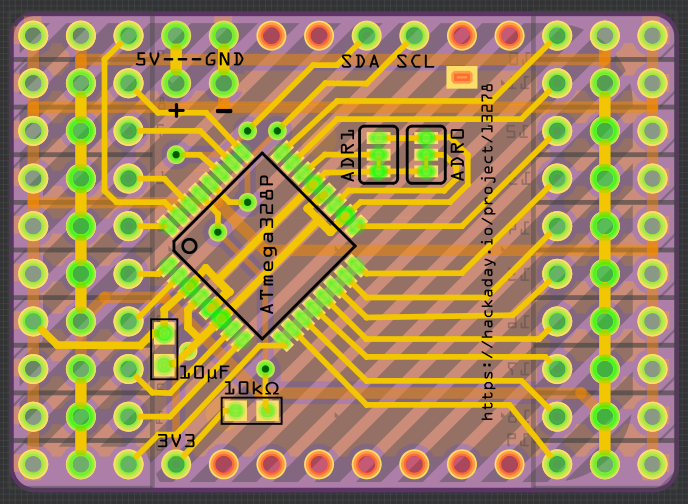
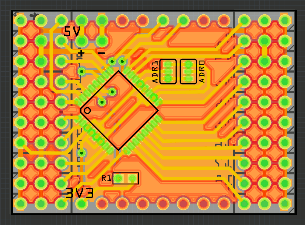
11/30/2016 at 19:23 • 0 commentsOK, the one-sided board experiment was fun, but not very practical. Especially since all the fab houses out there make two-sided boards by default, so I don't save anything. So I went back to the two-sided board, applied some of the improvements I discovered while working on the one-sided one, cleaned up the traces a bit, added a custom PCB outline with rounded edges and an outline of the D1 Mini on the bottom silkscreen, and I think it's ready for ordering. But I will wait one more day, maybe I will spot some more things.
![]()
-
One-sided PCB
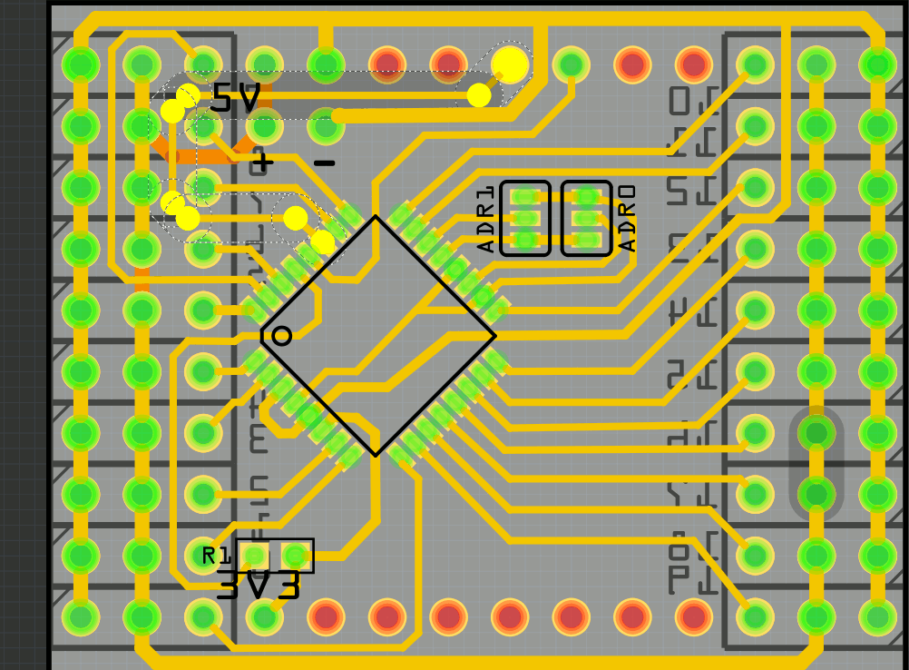
11/30/2016 at 14:15 • 0 commentsLooking at the design from the last log, I thought "Hmm, if only I had some more room on the sides for the ground and power lines, I could make this a single-sided PCB". Turns out I was wrong.
![]()
This is my best attempt at this. See that highlighted SDA line? If only it wasn't there, or I could fit it somehow next to the SCL line, everything would have been just fine. The track next to it would take it place, and the power rail could get a connection on top, where that track is now. Alas, there is no way to do that without a jumper cable.
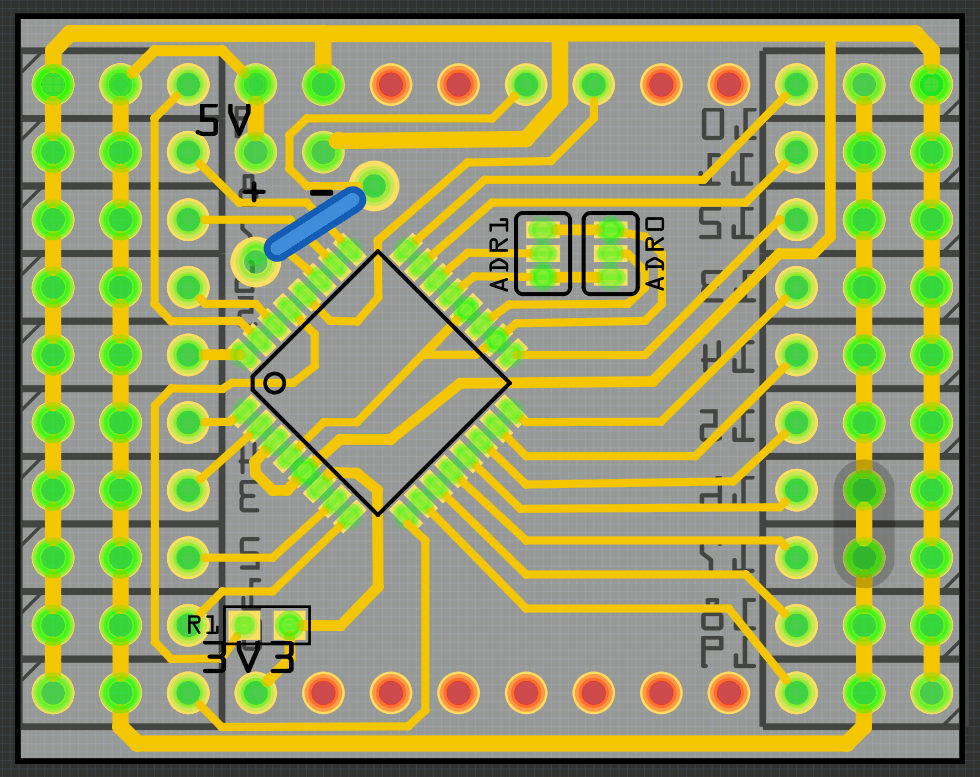
Oh well, a jumper can't hurt, can it?
![]()
-
20-channel Servo Shield
11/30/2016 at 13:05 • 1 commentYes, I keep refining the design. No, I don't actually need all those servo shields. But it's a fun challenge. So I made another one, this time controlling up to 20 servos at once.
![]()
Note how all the servo sockets are on the edges. That means that if you use angled 3×10 male headers, you can actually stack those. And with the address selection on the analog pins, you can have up to 4 shields at once. That's 80 servos. Of course, if you just reprogram them to use a different address, you could have hundreds of them.
So where are the two extra servo channels coming from? Turns out that if your ATmega328p uses an internal oscilator and you don't have an external oscilator connected, you can use those pins as gpios.
I'm still conflicted about whether to actually order this board or not. One idea is to order it, rewrite the firmware in plain C, and submit this to the 1kB contest...
-
Another Short
11/11/2016 at 11:50 • 0 commentsReleasing the design before actually receiving the boards and testing them turned out to be a mistake. Out of three boards that I got from OSHPark, two have a short between the servo power and ground. The third one seems fine.
So I opened the designs and looked through them carefully trace by trace -- but no short there. I opened the gerber files and looked through that -- no short either. The fact that two boards have a short but the third doesn't, suggests that there is some problem with some traces being too close to each other.
So I took a knife, and started cutting the traces on the board, trying to locate the short. I narrowed it down to the lower right quarter of the board -- specifically, to the ground fill on the bottom, between the servo socket pins.
![]()
Oops, seems like routing a "thin" trace between two 0.4mm pads doesn't leave enough room? This is a bit strange, because it always worked for me before -- perhaps I was just lucky.
Anyways, I went through the design and changed all the pads to 0.35mm, and also made some other traces passing through narrow spaces thinner. I also deleted the old designs from OSHPark, and added this new, corrected one. Ordered it, and we will see how that one works.
-
Released
10/09/2016 at 12:28 • 0 commentsI decided to make a formal release of the 18-channel servo shield.
I fixed all the problems I could find (including the short between power and ground), updated the firmware to have the servo sockets numbered in a sane order, and added jumpers on the bottom for changing the I²C address (so that up to 4 shields can be used at once without having to modify the firmware).
I also wrote simple libraries for MicroPython, NodeMCU and Arduino, with some examples.
I'm releasing the whole thing under a Creative Commons non-commercial license, because that's the license used by the PWM library that is included in there. I would love to release it under a license that allows commercial use (and to be able to order ready shields from China), however, that would require me to rewrite the firmware to not use that library (or get the original authors to change the license). Too bad I'm too lazy to do that.