deʃhipu
-
Shield Anatomy
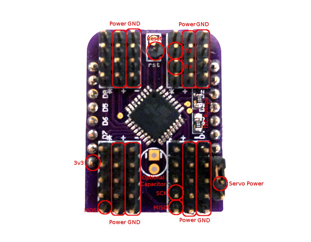
09/15/2016 at 19:20 • 0 commentsSince this board is so packed (18 servo sockets take a lot of space), I couldn't fit all the labels on it. So a bit of a legend is necessary:
![]()
The MISO, MOSI, SCK, RST, 3V3 and GND pins are needed for programming the chip after it's assembled. I'm just connecting the USBASP programmer to them and use the Arduino IDE with the Lilypad board selected. Then you also need to set the fuses with Avrdude:
avrdude -c usbasp -p m328p -U lfuse:w:0xE2:m -U hfuse:w:0xDF:m
to switch it from 1Mhz to 8Mhz. That's it, you can disconnect the programmer and use your new shield. Oh, before you program it, remember to add the resistor for the RST pullup on the back of the board. 10kΩ should be fine.You have two options for powering the servos. You can either connect the servo power pin to the 5V pin next to it, and power them from the same source as your D1 Mini, or you can use a separate power.
The order of the servo sockets on the board is pretty much random -- whatever was easiest to route. I suppose I could fix it in software, but for now I didn't even figure out yet which socket is which.
Ah, I also figured out why it didn't work with larger frequencies of i2c bus with esp8266 -- the fault is on the side of the esp8266 micropython, and its lack of support for clock stretching. A pull request is submitted to fix it.
-
18-channel Servo Shield
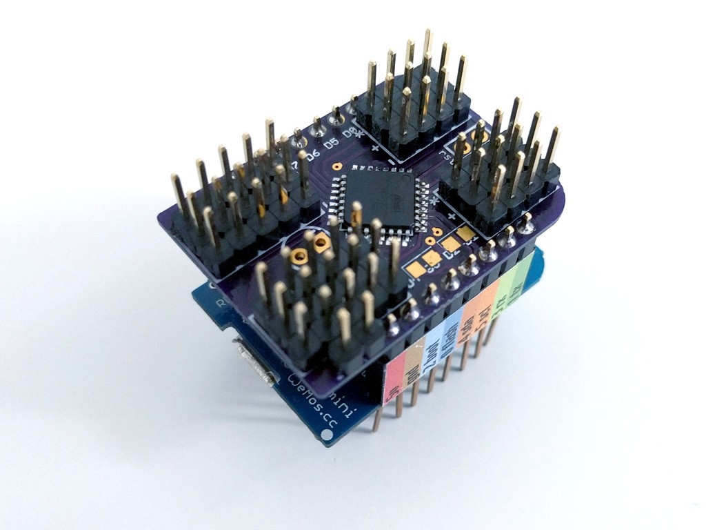
09/14/2016 at 12:21 • 0 commentsThe second approach is to actually use an ATmega328p chip communicating over I2C with the ESP8266, to generate PWM for 18 different servos. I had the code already from my #Servo Controller, so all I needed was a PCB for it. I considered using a Pro Mini here too, but finally decided that a bare atmega is enough -- I don't need an external oscilator, because neither the servo signal nor I2C are sensitive to timing differences.
![]()
So I received the PCBs from OSHPark, and assembled the shield. And of course I had a short between the 3.3V pin and the ground. One of the vias on my design got moved by mistake, and touched the ground fill. Fortunately that was easily fixed with a knife.
Then I connected my USBASP programmer, and with great help from @Christoph flashed the blink sketch, set the fuses to the right values, tested it, and then flashed my program.
First tests show that it works, except that for some reason I need to lower the frequency of the I2C bus to 150kHz from the default 400kHz, otherwise the slave gets stuck with its SDA pulled down as soon as it receives the second byte of transmission. I will poke at it some more and hopefully figure out what's wrong there.
-
Dumb 8-channel Servo Breakout
09/14/2016 at 12:11 • 0 commentsThe first one is only a servo breakout -- it doesn't have any components on it other than the pin headers. It lets you connect servos to all 8 available gpio pins (leaving only rx and tx), so that you can build a walking robot like #Katka.
To save space, the servos use angled headers. You can power them separately, or (after closing the juper on the back) from the 5V pin of the board.
There is a link to the OSHPark order page, and the design files and gerbers are uploaded in the files section.