-
On Using Feedback
10/08/2017 at 14:07 • 3 commentsI heard the Thomas Edison made 1,000 failed attempts before inventing the lightbulb sound byte over and over during grade school. There are a lot of anecdotes describing the hardships and long odds entrepreneurs overcome in the course of becoming successful, and I feel as though hearing them without some experience makes it difficult to really appreciate how much effort it takes to shrug off negativity.
---------- more ----------That's my guess anyway. I wouldn't know because I haven't had the displeasure of being drug through the mud by anything in life yet. Even so, I do know that just the smallest words against you can stand out at the end of the day and make it a bit harder to wake up the next morning and keep doing what you do.
The Hackaday Prize rounded up some feedback for Clunke recently. This has been a point of anxiety for me since submitting the project. I want design reviews. I want useful criticism. But I worried a lot about what might be said. I guess it's just the syndrome that happens when someone goes from isolated tinkering to the internet community.
Anyway, here's pretty much the only negative thing that was said:
![]()
So what if someone shitposts? Why does it bug me so much? It probably took, like, 7 seconds to leave that comment. And I've spent many minutes now stuck on it, trying to ignore this thing I read online that makes me feel bad about my project. It sucks. I have mad respect for people who deal with real rejection and come back from it time and time again.
Luckily, the majority of the feedback was legitimate, and concerned things that I ought to keep and eye on while working on Clunke:
![]()
My knee jerk reaction is that, no, Easy Buttons won't work. The above comment is just being dismissive and I should ignore it. Besides, I've taken one of those Easy Buttons apart before, and the mechanism is really space constrained and oddly design. And there's not a good place to wire a switch in, unless there are test pads on that PCB... Hrm... Maybe? Just maybe it could work.
That comment points out an important aspect of making AT switches: perhaps 3D printing them is both more difficult and more expensive than buying some generic button and modifying it. Maybe is good enough odds for me, and I'm honestly just curious, so I picked up an Easy Button from the local Staples:
Disabling the speaker is pretty straightforward:
Remove the screws under each rubber foot:
There's the mechanism. We're in luck, the PCB has nice points to solder to!
But when the silicon button is pressed, it doesn't short the circuit, instead it acts like a 500 ohm resistor:
Hmmmm. Well, it's that little dot of material inside the cone that causes resistance.. Maybe we can modify it to be a conductor.
Cut out a tiny piece of tin foil:
And glue it over that center bit of the cone:
While the glue is drying, get a mono cable:
Drill a hole in the button shell, and feed the cable through:
Solder the cable into the leads coming out of the switch component:
Slide the silicon cap back into its retainer:
Glue and tape the cable to keep it as much out of the way of the cap as possible:
And there you have it, an Easy AT Button!
Materials: Easy Button, audio cable (mono), tin foil, glue, solder.
Final price: $8.50. Not too shabby.
Tools required: drill, screw driver, soldering iron.
Now, I'm not about to go buy Staples out of their dwindling stock of Easy Buttons to convert them. I'm not sure how durable or suitable this switch is as an assistive button. It does work though, and nicely meets situations where an AT switch is needed immediately from local sources (the mono cable can be replaced with a regular audio cable, also from Staples).
tl;dr: Feedback FTW?
-
Quieter Printing - Adding a SSR
10/03/2017 at 13:50 • 0 commentsMy printrbot's motherboard (printrboard, as it is called) has a mosfet for controlling a heater for the print bed. Early on with the printer I noticed that this component tends to get a little toasty, so I used its 12V output to control a relay which handled the load better.
Except the relay goes CLACK ... CLACK ... CLACK as it turns the heater on and off to maintain a consistent temperature while the printer is running.
Yesterday I replaced the relay with a solid state relay (SSR), and it's certainly a relief to avoid the periodic clicking sound! I'm going to run some hour-long tests on it today to make sure everything works well, and then put it to use!
-
Making the Most with Money
10/01/2017 at 15:23 • 0 commentsSorry, the descriptive log title lost out to alliteration.
The semifinals prize money arrived. I've been in touch with two of the three other students who were on the design team for the original button, and we agree that the money should go toward testing and then making buttons. So the prize funds are for button materials only (i.e. not 3D printer parts). I'll be tracking it all on this post as I go.
---------- more ----------- 10-1-2017 - $64.33
- 2x 1KG reels of PETG filament from Atomic Filament.
- For learning to print PETG with and making version 2 buttons to test.
Prize Funds Remaining: $935.67
- 10-1-2017 - $64.33
-
Good Printers make Good Buttons
09/29/2017 at 02:56 • 0 comments- or at least they make any buttons at all.
My Printrbot (pictured above) has not had an easy life. Almost from the day it arrived as a kit, I've been ricing (in vain) to achieve lofty goals like queue based 24/7 printing. And in response it has spent more time than not being broken or mid-upgrade. Over this summer I decided to rip out a lot of the crazy stuff and try to get back to nice, reasonable working order. It's going well, but there's still a lot left to do.
---------- more ----------I'm a (self-proclaimed) terrible 3D printer operator. It seems as though endless hours slip away as I tune and calibrate, only to arrive at prints that look about as mangled as the first ones. After three years of owning one of these dang things, I still feel like a novice. If I'm going to make this printing-a-lot-of-buttons thing work, the printer and I need to find some common ground. To that effect, there's a lot of incremental changes I want to implement:
- The printer goes to work with me
- Takes up too much room at home, and my office is more conducive to keeping things tidy.
- Done!
- New base and scaffolding
- Just for aesthetics mainly.
- Done!
- Add auto-leveling
- Is a mess that needs a separate log post on its own.
- Done!
- More lighting
- I've learned that good visibility while working on these things is key.
- I have aluminum and led strips, just need to wire it up.
- Calibrate for PET-G
- It's the future, baby.
- Finish wiring external stepper drivers
- Probably the largest task, may require custom PCBs
- Make all external wiring easy to detach
- Being able to unplug the printer and physically move it is super underrated.
- Wire up loss-of-filament detector
- Will pause prints for me.
- Rebuild electronics panel
The idea is for the printer to remain usable in between each task, so it can continue to support Clunke development.
- The printer goes to work with me
-
Auto Leveling the Manual Way
09/29/2017 at 02:50 • 0 commentsThis is the recently-concluded story of my printrbot's trip to manual bed leveling land and back again.
---------- more ----------Above is a picture of the custom printer hot-plate I made while pursuing serialized printing. Before this my print bed had been aluminum, and worked with my printrbot's stock inductive leveling probe. Now the z-probe couldn't "see" any metal through that plate of borosilicate glass. What was I to do?
Well, first I put some copper tape on the glass (shown above) where common points for using the inductive probe were. That didn't give very good results though, so I decided to try and find a way to increase the operating distance of my sensor.. And how do you do that? By increasing the voltage to the sensor! It safely accepts 6-36V input, and I just assumed that it stepped down the signal output line to some 3-5V logic.
I assumed wrong. Highlighted in the image above is the fried mosfet which was used to step the z-probe signal line down to 5V logic for the microcontroller. When I ramped up the sensor's power voltage, the signal line followed, and blew out that component.
But I was in luck! I had just taken an EE course on transistors. With my newfound ability to sketch out an NPN circuit, I wired in a 5V tolerant replacement.
And I wound up just buying a beefier sensor to detect metal through the glass print bed:
This would have been a success, except the replacement sensor wasn't all that precise and I eventually gave up on it. I then removed the sensor entirely and put the print bed up on springs, leaving me to manually level the bed. This worked great, because I could really finely control the adjustment and get the first layer height really tuned in.
Fast forward to this summer. I realize that I've started having to re-level the bed between every print. The z-axis loses some steps somewhere after every print, and always returns to ~0.5mm instead of 0.0mm. It's starting to get old, so I decide the time is neigh for reinstalling a z-probe and returning the printer to auto leveling.
Guess what I did? Yup, I forgot about the delicate replacement transistor and I threw on the old high-voltage sensor which promptly fried the transistor. Crap, now what?
After more time than I care to admit, it dawned on me that as I went back to using a 5V sensor, scrounging up a replacement transistor shouldn't be necessary. The ATmega runs at 5V. The sensor runs at 5V now. They should be able to interface directly.
So that's what I did: just bridged the sensor line over to the microcontroller and pray the board schematic I found online was accurate.
It worked! The printer is back to printing, and I didn't have to go order a transistor online!
That's all, folks!
-
Printer Migration
09/29/2017 at 02:48 • 0 commentsThe printer is now safely at work!
---------- more ----------I didn't anticipate this, but my new office has the AC off when we're not around. I need to make sure the wider temperature cycle doesn't adversely affect filament. If it does I'll have to reevaluate things.
The picture above shows some of the completed upgrade tasks as well (new scaffolding, z-probe, stepper drivers). I'm going to try to refrain from making this project's logs all about messing with the printer, but fixing the z-probe was involved enough that I think it warrants a post here at some point.
-
Hackaday Prize and State of the Clunke
09/27/2017 at 03:14 • 0 commentsSo this project made it into the finals round of the Hackaday Prize! Given how awesome the other assistive tech projects I saw were, I'm still pretty surprised.
I've delayed quite a while with this log entry; right now is a pretty tumultuous time for me (just started a new job) and I wanted to make sure all the bases were covered before posting anything. Let's quickly take a look at where the Clunke Button stands today, and then I'll get back to the Hackaday Prize.
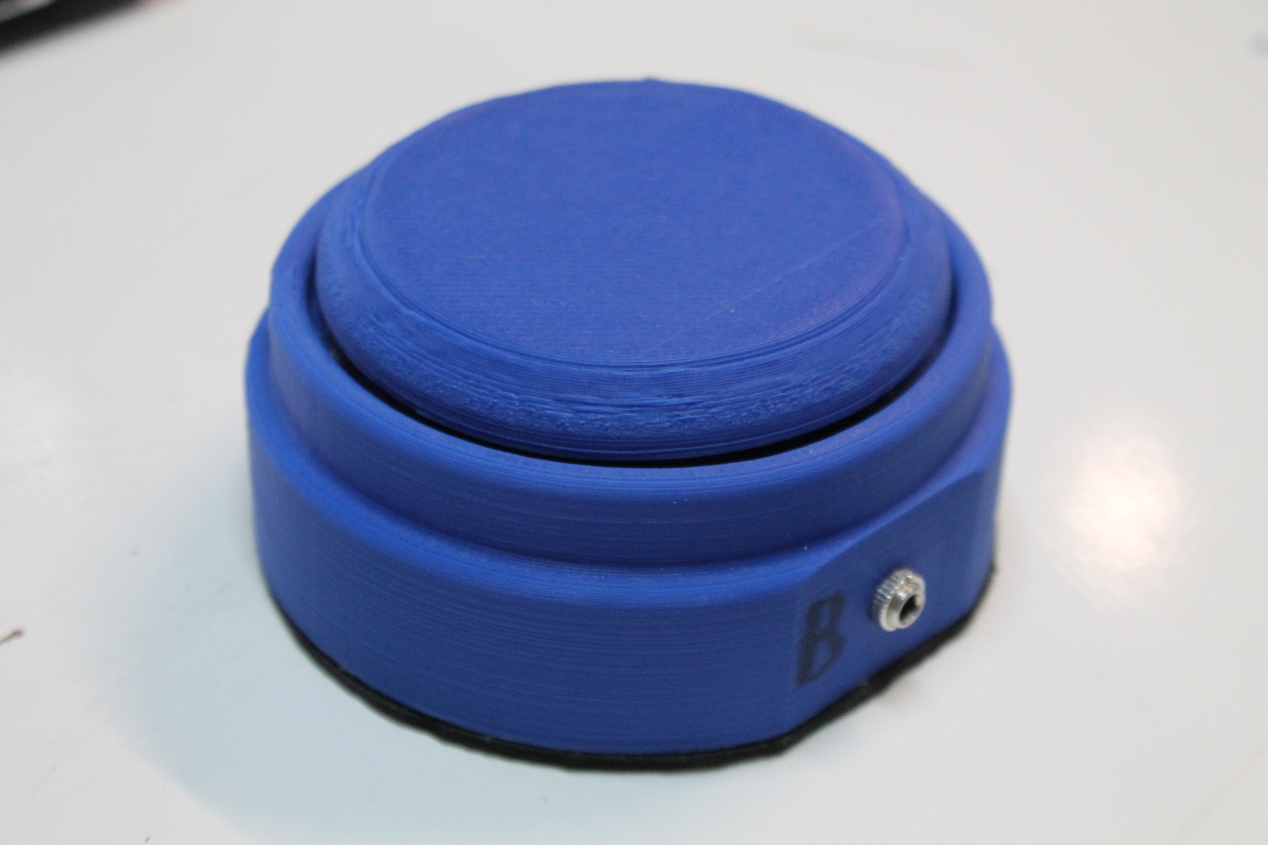
---------- more ----------The Clunke Button has an initial design already available for printing:
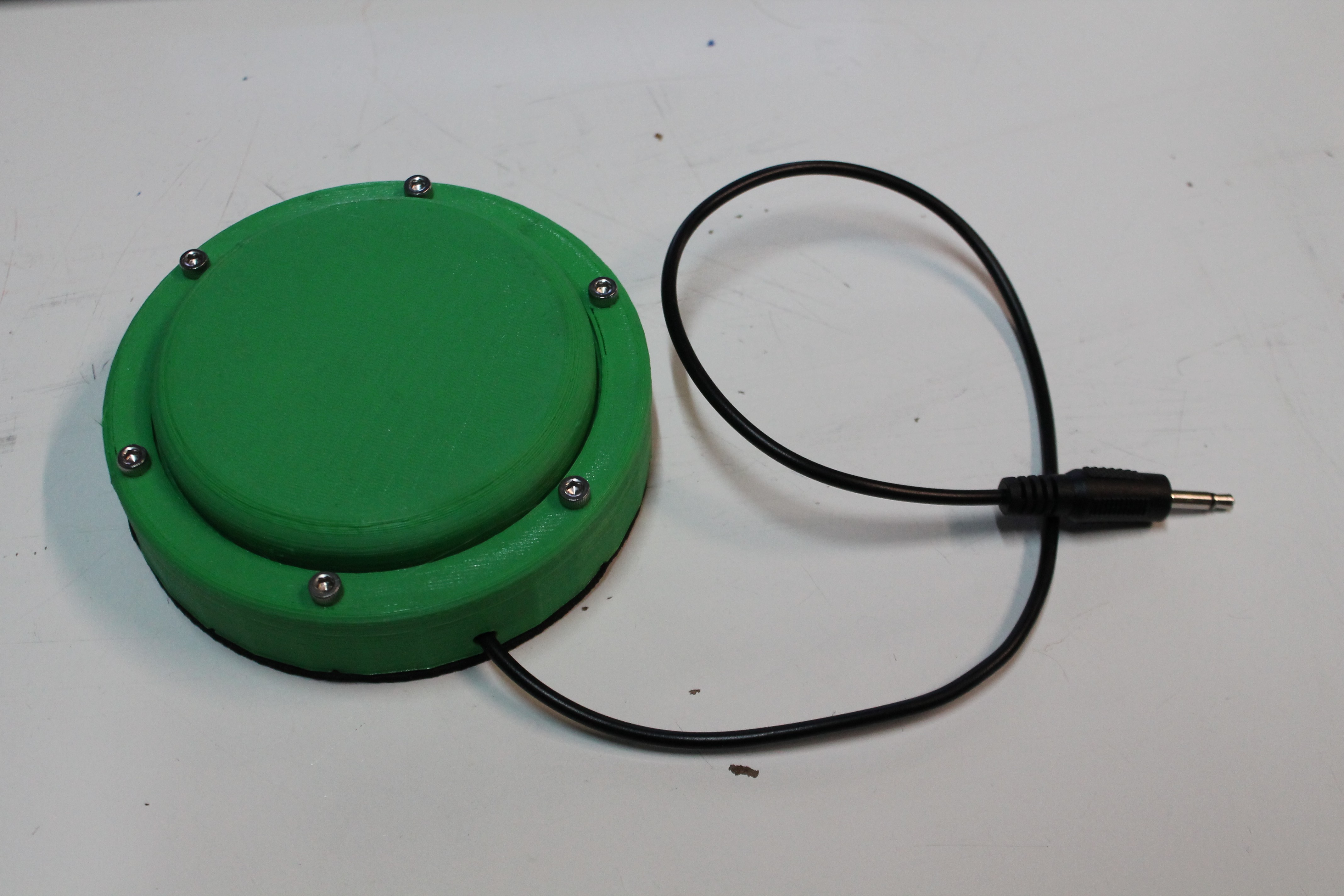
This button does work, but it has several shortcomings -- the most grievous of which is that the connection between the cap and base is not robust at all. So another button design was made:
This new button addressed some feedback from professional review, and is more durable, but it binds up when pressed from the edge of the cap, which makes it no more suitable than the original for regular use.
My first thought on being in the finals round of the Hackaday Prize was that this was a chance to challenge myself to iterate on Clunke and reach a product I'm happy with. But there's a nagging thought that keeps surfacing: the other buttons. When I started working on Clunke in 2015, the actual goal was to make buttons, but I didn't see any existing designs. Fast forward to 2017 and there are several really good ones. I find myself worrying now that by having Clunke listed online, I'm distracting potential users from other button solutions that work better. Since learning that Clunke made it through the seminfinals round, I've been evaluating whether or not to shutter the project, and now I've reached a decision.
I'm going to compete in the finals round. My little project doesn't stand a chance against the competition, but I'm going to put my best effort into it because it's the right thing to do. At the conclusion of the finals round, I'm going to conduct my own go / no-go review of Clunke. If it hasn't reached a point where I feel comfortable with others downloading and printing it, I'll cease working on it, and make the available project pages reflect the defunct status.
Why? Because if Clunke doesn't "ship" by the end of October, I'm going to start printing the other buttons. I've decided that as much of the prize money as possible is going to go toward the raw materials for printing and assembling AT buttons to distribute. A local organization has graciously offered to help me with testing and revising Clunke, and afterwards with bringing printed buttons (whatever design they may be) to users. I've had a lot of fun playing with CAD tools and printing thing that will never be used, but it's about time to finally shoot the engineer and start sending out affordable assistive switches.
-
Because of course it uses an ESP8266
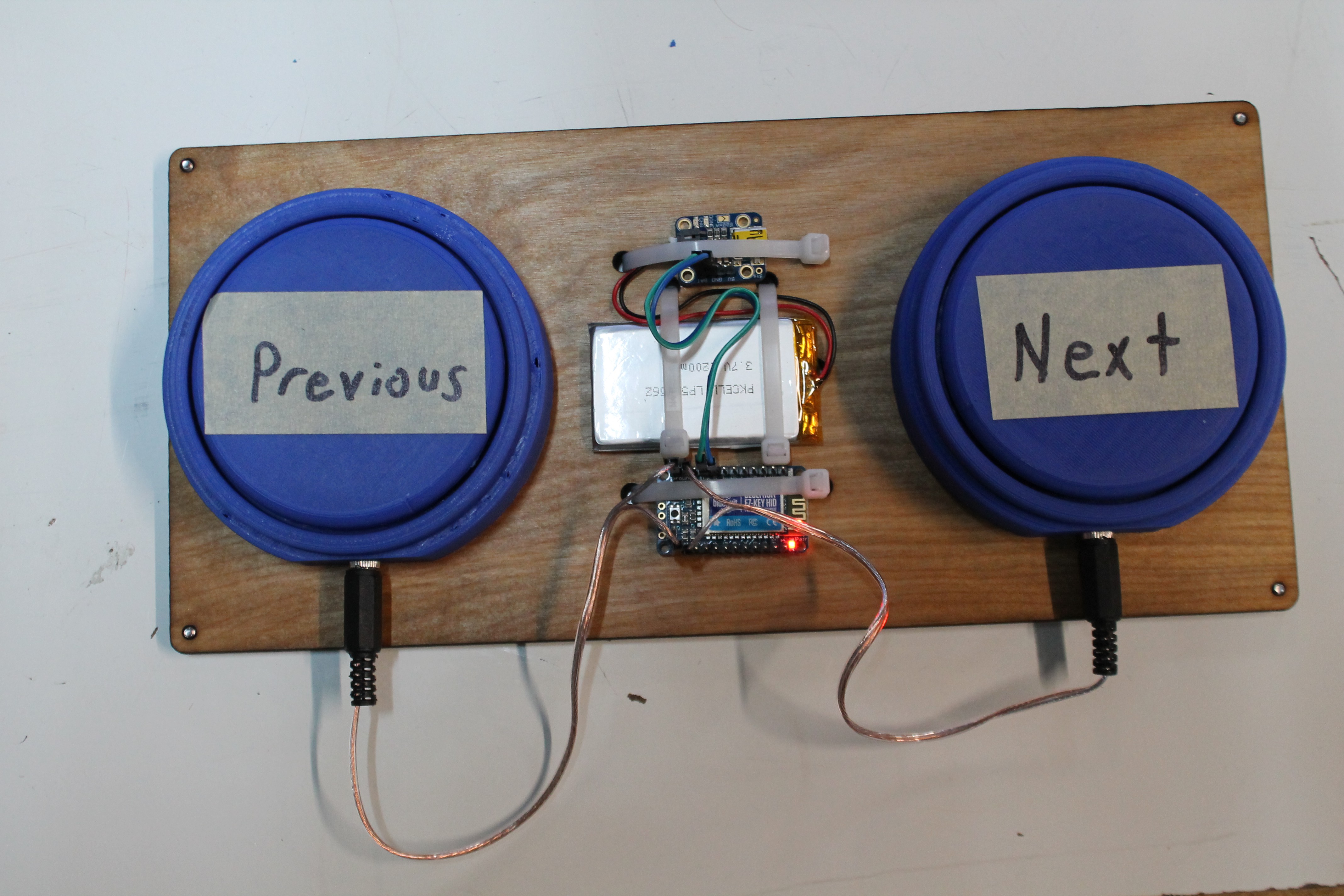
09/04/2017 at 07:12 • 0 commentsThis is a little off-track from the 3.5mm assistive button objective, but nevertheless I'd like to visit a brief moment in the project's journey when we decided that these AT buttons could also be hacker fodder:
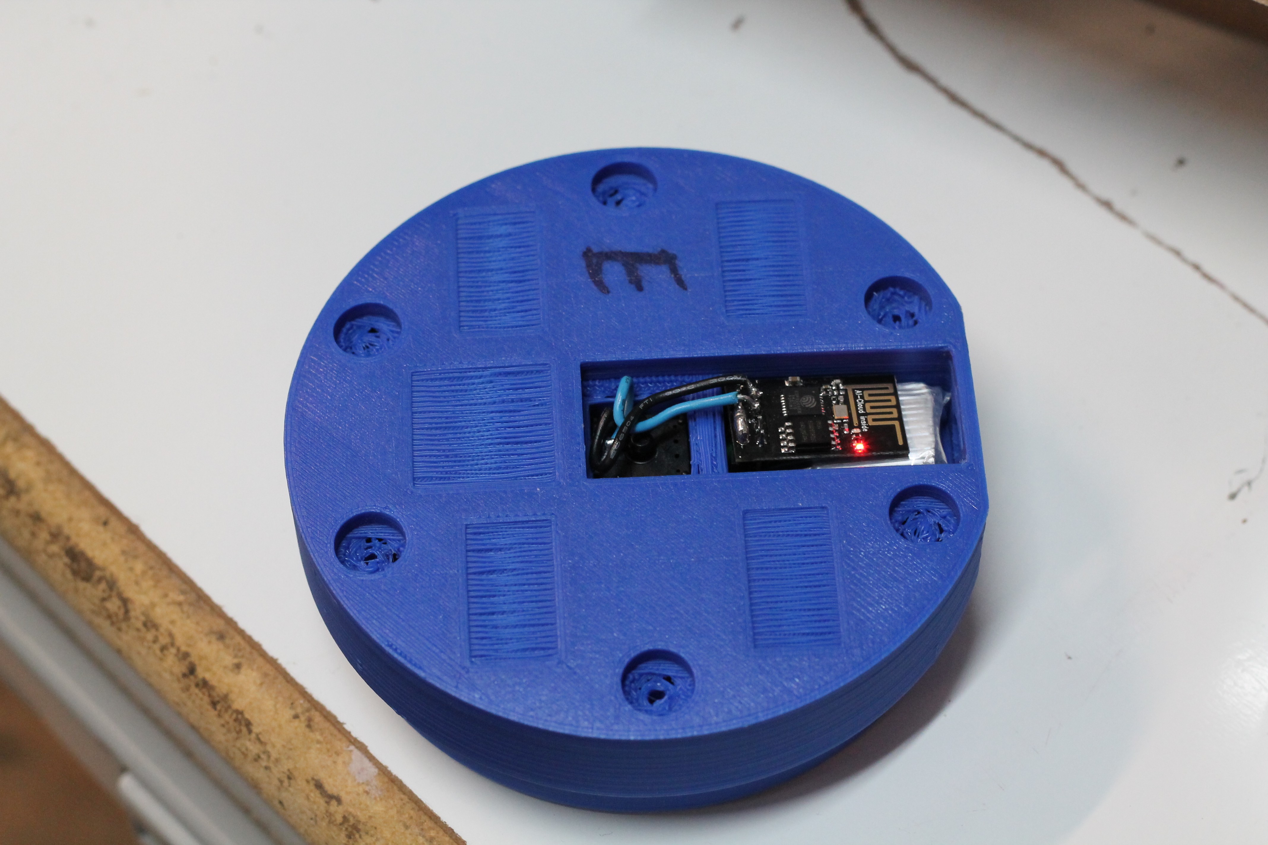
---------- more ----------The circumstance leading up to this abomination is pretty clear: we had to give a presentation to an audience of a few dozen, and wanted them to be able to try the button for themselves. So here enters an ESP-01 and a small RC battery.
The ESP firmware and companion desktop ticker are on github and pretty minimalistic.
Amazingly, the ESP ticker had only a few milliseconds of delay between pressing the wireless button and updating the display. That left only battery life as a design consideration, which we thoroughly tested:
(no lockout, so it just keeps spamming button presses)
Again, amazingly, the button's diminutive battery held out of over an hour of this abuse! It's enough to make me wonder if a 802.11 wireless button could be used for serious applications. Bluetooth AT buttons are already available on the market, and we found a way to make our printed buttons operate the same way, so why stop there? With the increasing popularity of LAN and IOT based home automation, a web-connected button could become quite powerful in terms of accessibility. Just something to consider..
The bluetooth buttons, also used during the presentation:
-
Designing for Warp
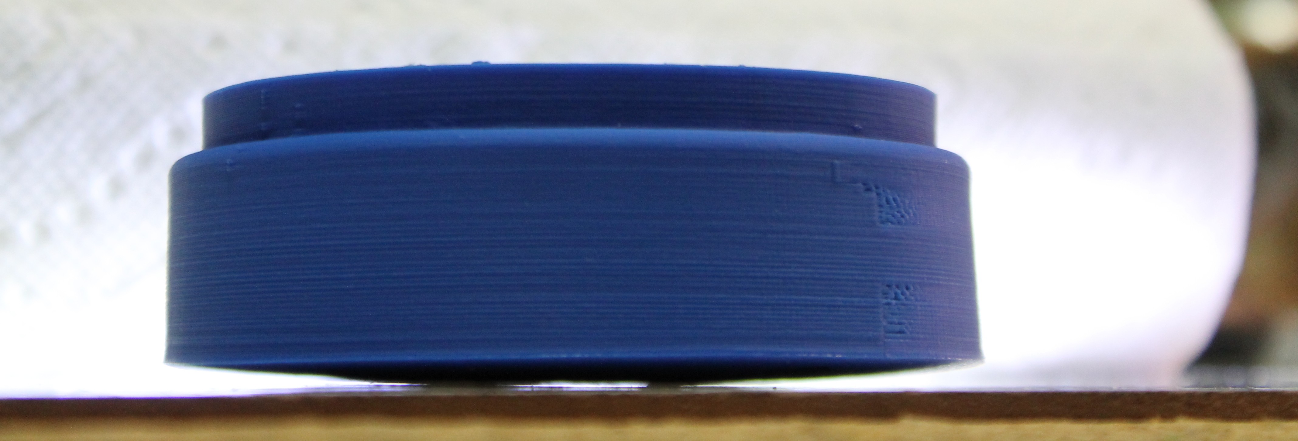
09/04/2017 at 06:46 • 0 commentsThe first couple of AT buttons we printed turned out well, but we quickly noticed a trend of warped bases where the edges of the PLA button tended to lift off of the printer's build plate.
---------- more ----------The curved bottom meant buttons would rock and make using them difficult. A solution was needed, and since I couldn't manage to tune the warping out of our printer's configuration, I turned to the button's 3D model.
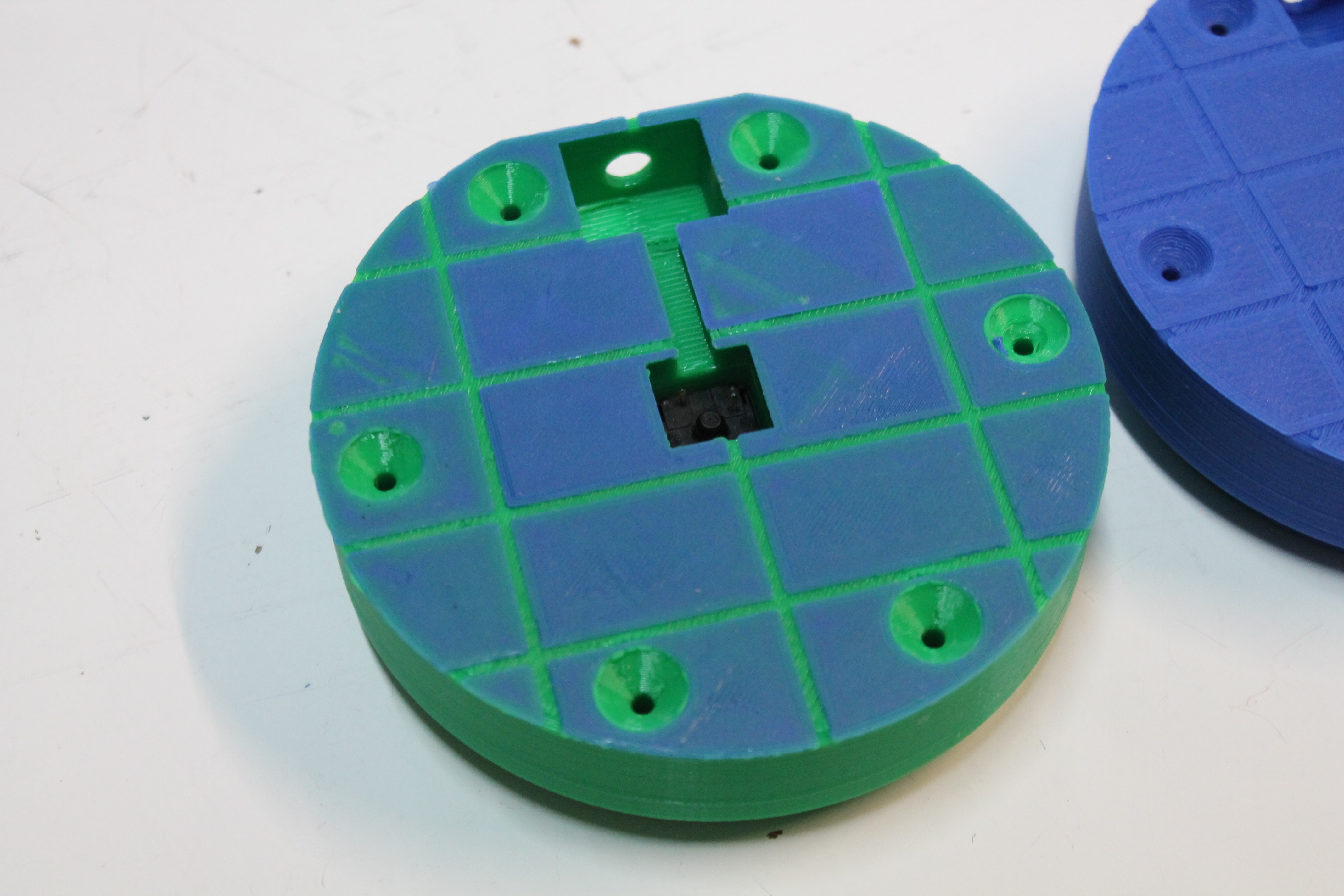
My first assumption was that warping was being caused by the large surface area of the button's base layer, so I made cavities in the first few layers to decrease the surface area:
Results were disappointing. The buttons kept warping pretty much as they had prior to the modification.
Luckily, I eventually came around to the notion that warping was a function of overall distance, not surface area. This meant we had to make the base layer contain less long segments:
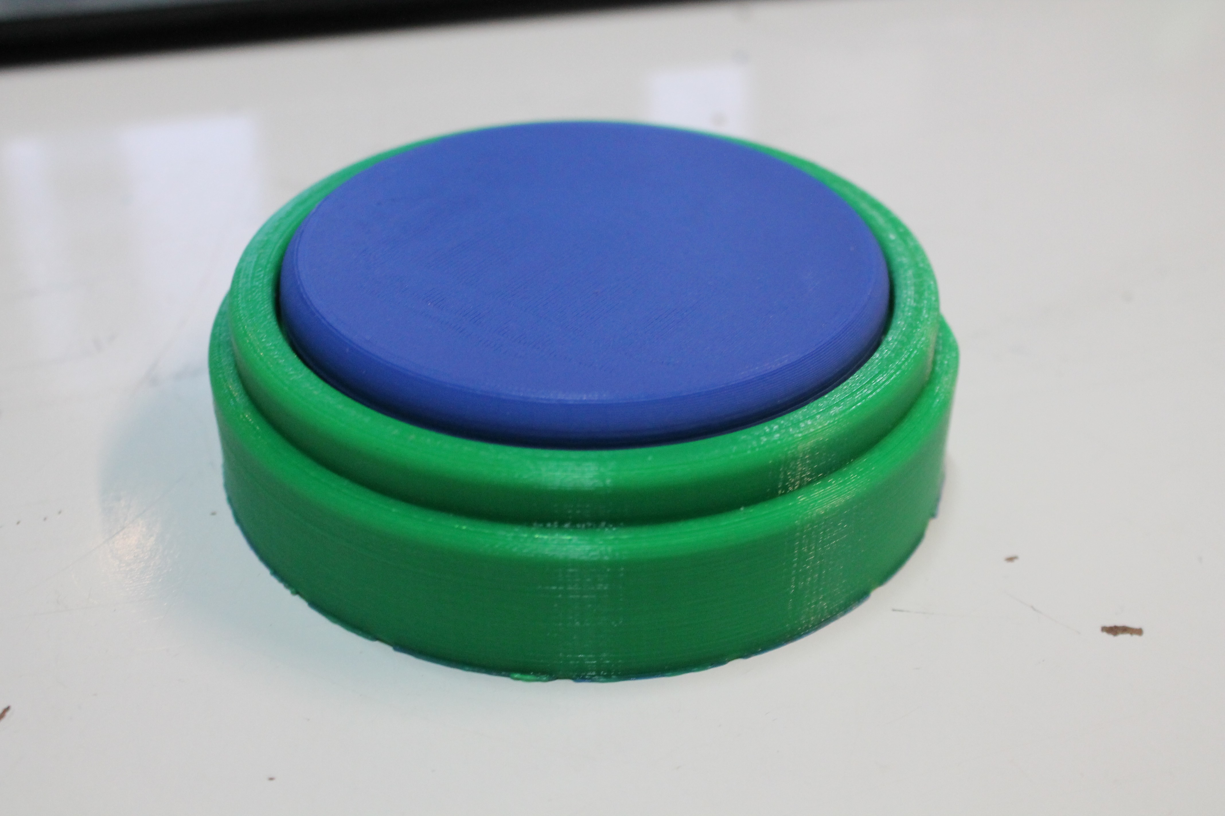
Success! The buttons started printing very flat:
As you can see, the "fixed" buttons also started using a different color PLA filament. In retrospect, our small-lines solution may have been correlation instead of causation, so another pass of investigation is due at some point.
-
Why not Lasers?
09/04/2017 at 06:02 • 0 commentsAs part of the senior design project, we developed a prototype keyboard that didn't require fine motor control to use. It's construction involved both 3D printed mounts and laser cut plywood.
![]()
So why didn't we use the laser cutter to make the adaptive button as well? Certainly the plywood would be cheaper, and even provide a more aesthetic result with some sanding and stain.
Well, the main consideration is that the keyboard was an unvalidated concept, something we hoped would find traction with users. The buttons, however, already had a clear use case, market, and demand; these buttons needed a design with local, small scale production in mind.
With the goal of making buttons easy to create, let's compare the laser and printer:
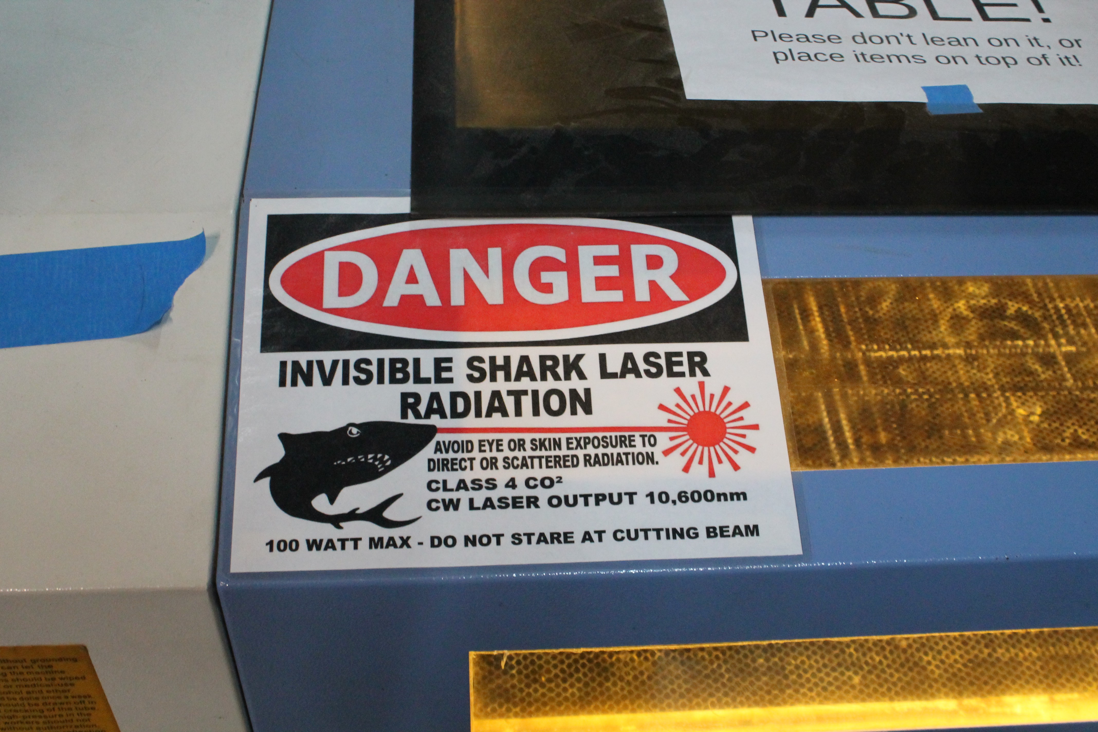
- The laser cutter is somewhat more dangerous than a 3D printer, requiring more attention to safety during operation (see above).
- The laser bed takes up 4 by 8 feet of floor space, whereas our 3D printer sits on a desk.
- The laser creates fumes and needs industrial ventilation. The 3D printer isn't proven innocent in this category, but with certain filaments the air-based hazards can be considered mitigated.
- Prices vary wildly among both 3D printers and laser cutters, but in our case we focused on making the button printable with sub $1000 FDM printers. Which meant that the $5000 laser cutter was much more expensive, again putting it out of reach for many DIY-ers who we want making these buttons.
So the printer made an all-around better platform for creating small gadgets in local communities.
 Christopher

