According to the great Archive stored by Bitsavers and after also consulting this amazing Pertec interface explanation at Sydex Inc., the Pertec interface consists of the following:
- Connectors: some times 1 x DB62M - tape drive cable, DB62F controller side, some times 2 x Card Edge (CE)50M - tape drive Pertec formatter or CE50F on the cable each marked P1 and P2, J1 and J2.
Both connectors have almost the same signals. Some drives support all of them, some drives just a part of them.
The following signals correspond to all 1/2" 9-track tape drives with densities of 1600 Bytes per Inch (BPI), 3200BPI and 6250BPI, both Phase Encoding and Group Coded Encoding methods:
/* test write  IW0....IW7
                            [W7] [W6] [W5] [W4] [W3] [W2] [W1] [W0]
                     15  14  13  12  11  10   9   8   7    6    5    4    3    2    1    0
         PB   0   0   0   0   0   0   0   0   0    0    0    0    0    0    0    0
  [WRITE]                                 X    X    X    X    X    X    X    X
 [WRMASK] 1   1   1   1   1   1   1   1   0    0    0    0    0    0    0    0
    WRMASK = 0b1111111100000000 = 0xFF00;
*/

// Write lines - IBM-style ordering, meaning Bit 0 = MSB,
// Bit 7 = LSB

/*   test IWP   PB8
                                    [WP]
         15  14  13  12  11  10   9   8   7   6   5   4   3   2   1   0
     PB   0   0   0   0   0   0   0   0   0   0   0   0   0   0   0   0
 [IWP]                                X
 [WRMASK] 1   1   1   1   1   1   1   0   1   1   1   1   1   1   1   1

WPMASK = 0b1111111011111111 = 0xFEFF;

*/
// IWP  Write parity - odd parity computed over IW0–IW7
// and on some drives is ignored and computed by the formatter.


// CONTROL SIGNALS
// Activated by the controller/mainframe side - operations
// for the drive to execute

/* test CTRL0  PB9...PB15
       HISP EDIT WFM ERASE REV  WRT LWD
         15  14   13  12    11  10   9   8   7   6   5   4   3   2   1   0
     PB   0   0    0   0     0   0   0   0   0   0   0   0   0   0   0   0
  [CTRL0] X   X    X   X     X   X   X
 [C0MASK] 0   0    0   0     0   0   0   1   1   1   1   1   1   1   1   1
    C0MASK = 0b0000000111111111 = 0x1FF
*/

#define ILWD    0x200  //  Last word—Used to tell drive that this is
                       // the last word (byte) to be written
                       //  in this record, Must be asserted at least
                       // 300 nsec. before trailing edge of final
                        //  IWSTR pulse.

#define IWRT 0x400   // Write — When asserted with IGO begins a write sequence.

#define IREV    0x800   // Reverse — When asserted, indicates operation is
                        // to be performed in the reverse direction.

#define IERASE 0x1000 // Erase—When asserted with IWRT and IGO,
                      // causes tape to be erased, usually for a
                      // predetermined length. Usually used to
                      // recover from write errors or provide extra
                      // space for mode changes (Read after write).

#define IWFM 0x2000   //  Write filemark; When asserted with
                      // IWRT, writes a filemark.

#define IEDIT 0x4000  // Edit—Not implmented on all drives.
                      // modifies/updates records inside tape files.

#define IHISP 0x8000  // High speed select—When asserted 1 µsec. before
                      // and then with IGO (de-asserted any time after
                       // the trailing edge of IGO selects high-speed
                        // (streaming) mode.

/*
  test CTRL1
                                               RTH1 RTH2 REW RWU LOL GO
        15  14  13  12  11  10   9   8   7   6   5   4   3   2   1   0
    PC   0   0   0   0   0   0   0   0   0   0   0   0   0   0   0   0
[CTRL1]                                          X   X   X   X   X   X
[C1MASK] 1   1   1   1   1   1   1   1   1   1   0   0   0   0   0   0
[C1MASK = 0b1111111111000000 = 0xFFC0
*/

//CTRL1:

#define IGO   0x01  // Initiate command—Pulsed low for at least 1µsec.
                    // to start command execution. The formatter address
                    // lines must be stable throughout the pulse and
                    // until IFBY drops.

#define ILOL  0x02  // Load on-line—Pulsing this line at least 1µsec.
                    // begins the tape load sequence on many drives.

#define IRWU  0x04 //  Rewind and unload—A pulse of at least 1 µsec.
                    // initiates a rewind-with-unload and sets
                   // drive offline. Some drives require that IREW is
                   // also asserted.

#define IREW  0x08 // Rewind—A pulse of at least 1 µn;sec. starts the
                   // tape rewind sequence. Completion is
            // // signalled by IRWD and IRDY being asserted by the drive.

#define IRTH2 0x10 //  Write density select 2—On some drives, this signal,
                   // along with IRTH1 is used to
                   // select the drive write density. If it is implemented,
                   // it is valid only at BOT and must be asserted with IGO
                    // during the first write sequence.
#define IRTH1 0x20      //


/* test ADDR
                                                         FEN TAD1 TAD0 FAD
          15  14  13  12  11  10   9   8   7   6   5   4   3   2   1   0
     PF    0   0   0   0   0   0   0   0   0   0   0   0   0   0   0   0
[ADDR]                                                     X   X   X   X
[ADDRMASK] 1   1   1   1   1   1   1   1   1   1   1   1   0   0   0   0
 ADDRMASK = 0b1111111111110000 = 0xFFF0
*/

#define IFAD  0x01  // PF0    Formatter address
#define ITAD0 0x02 // PF1 Transport address bit 0 (MSB!)—Used to address
                    // multiple drives on a single controller.
#define ITAD1 0x04 // PF2   Transport address bit 1 (LSB!)
#define IFEN  0x08 // PF3 Formatter enable — This signal should normally
                   // be asserted all the time.
                  //  If dropped for a minimum of 2 µsec., aborts any
                  // comman that asserts IDBY
                  // (I/O, skip, but not rewind or unload).

// #########################################################

/* test READ
                                          [R7] [R6] [R5] [R4] [R3] [R2] [R1] [R0]
          15  14  13  12  11  10   9   8   7    6    5    4    3    2    1    0
     PE    0   0   0   0   0   0   0   0   0    0    0    0    0    0    0    0
   [READ]                                  X    X    X    X    X    X    X    X
[READMASK] 1   1   1   1   1   1   1   1   0    0    0    0    0    0    0    0
 READMASK = 0b1111111100000000 = 0xFF00
*/
// Read data lines - IBM-style ordering, meaning Bit 0 = MSB, Bit 7 = LSB
#define IR0    0x01
#define IR1    0x02
#define IR2    0x04
#define IR3    0x08
#define IR4    0x10
#define IR5    0x20
#define IR6    0x40
#define IR7    0x80

/* test RP
                                     [RP]
          15  14  13  12  11  10   9   8   7    6    5    4    3    2    1    0
     PE    0   0   0   0   0   0   0   0   0    0    0    0    0    0    0    0
    [RP]                               X
  [RPMASK] 1   1   1   1   1   1   1   0   1    1    1    1    1    1    1    1
 RPMASK = 0b1111111011111111 = 0xFEFF
*/

#define IRP    0x100  // read parity

/* test STAT0
         RSTR DBY DENT FMK CER HER FBY
           15  14   13  12  11  10   9   8   7    6    5    4    3    2    1    0
      PE    0   0    0   0   0   0   0   0   0    0    0    0    0    0    0    0
  [STAT0]   X   X    X   X   X   X   X
[STAT0MASK] 0   0    0   0   0   0   0   1   1    1    1    1    1    1    1    1
 STAT0MASK = 0b0000000111111111 = 0x1FF
*/

// Status lines -  reports sent by the drive

#define IFBY    0x200    //  Forrmatter busy — Set by trailing edge of IGO,
            // clears when command finished (but you can send a new command
                    //as soon as IDBY clears)

#define IHER    0x400    //   Hard error — Pulsed during IDBY when a hard
                        // data error (or illegal character in the IRG) is
                        // seen.
                      // Note that most modern formatters correct this error
                        // automatically.

#define ICER    0x800    //  Corrected error — This signal is pulsed during
                         // IDBY when a single-track dropout is successfully
                         // corrected using the parity information.

#define IFMK    0x1000    //  File mark—Pulsed during IDBY when a tape mark
                          // is seen.
#define IDENT   0x2000    //  Identification—Asserted while drive is actually
                      // reading the PE ID burst, dropped the rest of the
                      // time so it's up to the controller to catch it and
                      //remember.

#define IDBY  0x4000  //  Data busy—This signal is asserted during I/O phase
                      // of read or write commands. It generally lags a few
                      // milliseconds after the drive asserts IFBY.

#define IRSTR  0x8000  // Read strobe—Pulses low for at least 200 nsec. when
                        // data on IR0-IR7 and IRP are stable before leading
                        // edge; typically held for 200 nsec. but this is
                        // not a requirement. Note that data is made available
                        // there is no check made to ensure that the host has
                        // picked it up.

/* test STAT1     !!!! LDP - load point / BOT
                                   SGL WSTR RWD FPT SPEED ONL HIDEN  RDY  LDP  EOT
           15  14   13  12  11  10   9   8   7    6    5    4    3    2    1    0
      PI    0   0    0   0   0   0   0   0   0    0    0    0    0    0    0    0
  [STAT1]                            X   X   X    X    X    X    X    X    X    X
[STAT1MASK] 1   1    1   1   1   1   0   0   0    0    0    0    0    0    0    0
 STAT1MASK = 0b1111110000000000 = 0xFC00
*/

#define IEOT    0x01   //End of tape — Asserted whenever the tape is past
                       // the EOT marker, clears when the tape is
                       // backspaced past it.

#define ILDP    0x02   // Load point — Asserted whenever the tape is at the
                        // load point

#define IRDY    0x04    // Ready — Signals that tape is fully loaded, on-line
                        // and not rewinding. This must be asserted by the
                        // drive before it will accept any command.

#define IHIDEN    0x08    // High density mode

#define IONL    0x10    //  Online — Asserted when the drive is online; clears
                        // within 1 µsec. of being taken offline.

#define ISPEED    0x20    // High-speed — This signal is asserted when commands
                          // are executing in high-speed mode; that is when
                          // the drive is not operating in start-stop mode.

#define IFPT    0x40    //  File protect — This signal is asserted continuously
                        // when the tape is not write-enabled
                        // No ring - no write.

#define IRWD    0x80    // Rewinding — This is asserted by the drive while the
                        // tape is rewinding.

#define IWSTR    0x100  //  Write strobe — Pulses low for at least 200 nsec.
                        // when the drive is ready to accept data. This is
                        // roughly similar to an "Acknowledge" signal after
                        // data has been received. The next data byte can be
                        // presented immediately.

#define ISGL    0x200    // Selected drive fault on some drives; not connected
                         // on others. If used, it is cleared by
                         // de-asserting, then reasserting IFEN.
Note that the interface uses inverted logic, meaning if a signal is at +5V is false, and when dropped at 0V is true.
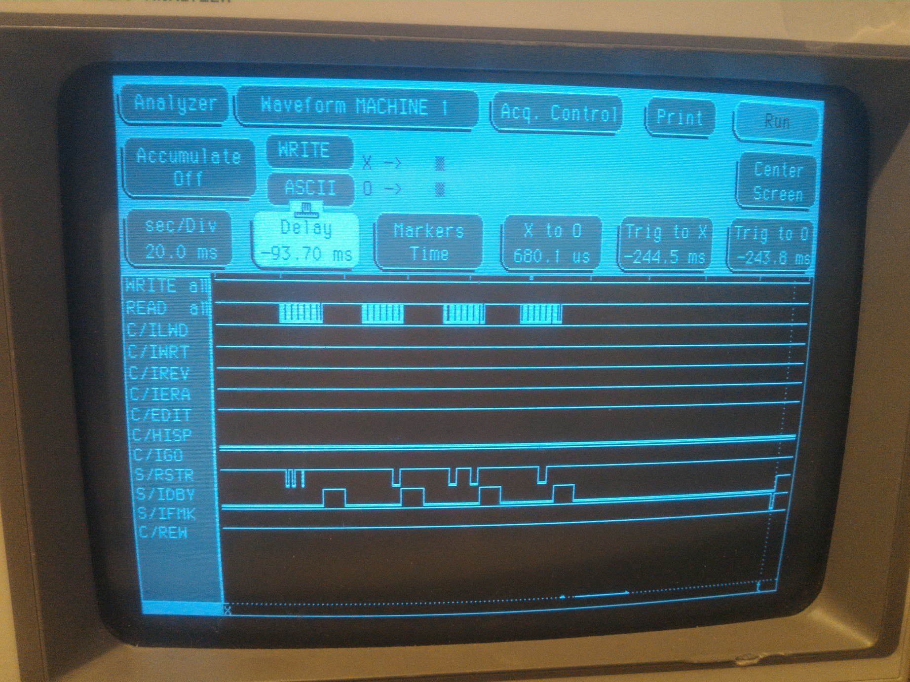
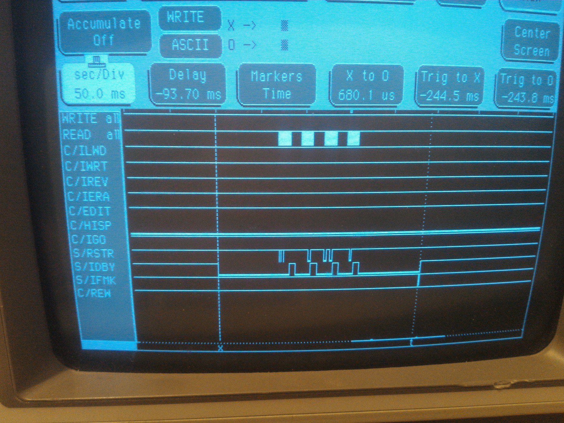
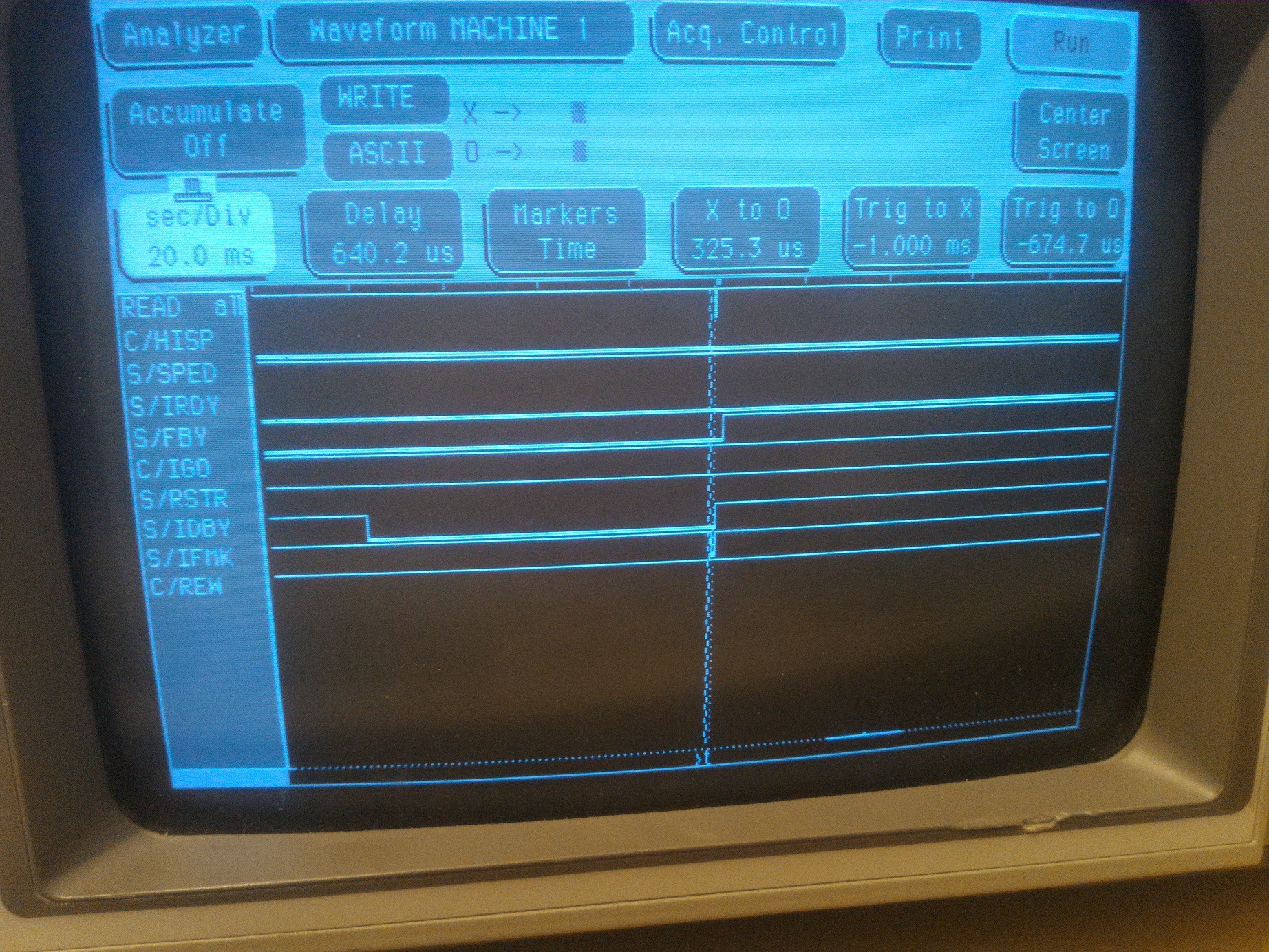
The following data analysis shows what is happening during a "READ" signal - one sort pulse of /IGO.
Assuming the tape is online (IONL = 0V) and ready (IRDY = 0V), the controller pulses "IGO". At startup, the drive drops IFBY (0V) and after the reels reach the operational speed, IDBY is dropped (0V). When data is ready on the bus, /IRSTR drops for a short time (0.8 uS). After 1.2uS it is dropped again signaling a new data transfer (read) should be performed on the host side.

After the end of each block, IDBY goes high (+5V/false) and the drive is ready to accept a new command.

The end of a file is signaled by dropping IFMK.
 After IDBY raises there is a time window before IFBY also raises. This time window is used by the host to reinstruct the tape drive for a new operation. If a continuous read is desired until the end of data (2 consecutive filemarks on the tape), IGO should be pulsed during this time window. Failure to do so will cause the tape to rewind at the end of last read block, stop and wait for a new command, then start spinning the reels until operational speed is reached. This is a time consuming process and unnecessary wears the tape especially when communication is attempted on the host side without using interrupts.

End of data - not to be confused with IEOT (end of tape) - it is signaled by a second filemark and an empty read buffer. The drive waits for a new command. If append data is desired, the drive will be signaled to perform the following operations: rewind a block (the empty block shown above), erase the second filemark, write new stuff, write a new filemark (end of file) and a second filemark to signal <end of data>
[END OF TRANSMISSION]
 [skaarj]
Discussions
Become a Hackaday.io Member
Create an account to leave a comment. Already have an account? Log In.