Close
0%
0%

THE PERTEC WHISPERER-MAINFRAME TAPE DRIVE EMULATOR

A.K.A. THE 9 TRACK TAPE DRIVE COMMUNICATOR
Talking to Mainframes Era Reel to Reel 9 track tape drives

Similar projects worth following
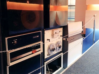
While wondering in some abandoned space you stumble into a room filled with a mainframe from the 1970s-era and first thing flowing through your head is to turn on this monster. 9 track tape drives are fun to tamper with. The interfaces of those era were either UNIBUS, HP-IB or PERTEC Industrial Standard. The last one survived until the middle of the 90s and was adopted as a de-facto standard for industrial machines using tape drives. In order to keep compatibility, Pertec Formatters were built. The Pertec Computer Corporation (PCC) also created their own version of Floppy Disk Drive Interface which was later adopted as a standard and survived until the 2000s when it was removed from PC computers.This project consists of building and experimenting a microcontroller-based device to interact with tape drives.

https://www.youtube.com/watch?v=aJTTsaFbPDE

First - project logs shortcuts: 

1. Mainframes behind the Iron Curtain  

2. Concept design - schematics and discussion - short system description;

3. Pertec interface schematic - big pain for the eyes;

4. Arduino Mega 2560 central processing unit - prototype failure;

5. PCB - First prototype - failure;

6. Experimenting with VHS 1/2" tape (I) - 5 km (16404 ft) instead of 2600 ft! Cool!

7. Second prototype experimental schematics - don't try this at home, it's not final

8. The motherboard (1) - the anticipation of many sleepless nights;

9. The motherboard (2) - this is for people who enjoy pain;

10. It's alive! ALIVE!    -   the magic is flowing;

11. Jack in the Box  - system installed inside a 4U rack-mounted enclosure and some experimental graphics using a HP1662 logic analyzer;

12.  Pertec interface signals explained  -  some kind of ancient digital zoo;

13.  The RAM Buffer  and some software-related details.  Bad luck, it took me a whole month to make rambuffer work as a big file;

14. Project published on Hackaday Blog - thank you.

15. Whispering in host mode - description of the internal tape image storage format modified after SIMH .TAP format;

16.  Video demonstration

17. Industrial-grade PCBs finished after totally 9 months of design spread across 4 years

Work in progress:  back into the surgery room to solder all the parts. By hand.

___________________________________________________________

Here are all the previous steps:

[2009] acquired a 9 track tape drive;
[2010] recovered a communist-era Digital Alpha Numeric Terminal vt100-compatible;

[2013] found an old mainframe and brought it home part by part. Also communist clone;

[2014] acquired the second tape drive - power supply broken;

[2018]  Restoration project started

First step - getting the tape drive working.

This project aims to build an interface between modern and old tech. In order to get the monster working I need whatever data I can get: operating system, backup tapes, software, floppy disks, anything.

Industrial 9 track Tape Drives talk Pertec and this is the interface I am going to focus for now. So these are the functions:

1. PERTEC (9 track tape physical drive) to MicroSD Card (host microcontroller) converter - read/write data from/to tape;

2. PERTEC Drive Emulator (micro-controlled sd-card) to Mainframe (host) - acting as a genuine 9 track tape drive peripheral;

3. PERTEC (9 track tape physical drive) to SCSI (host) Converter - some people decide these devices should cost a ton of money and I want to have some fun by telling a little bit of their secrets;

4. 9 Track Tape-based USB Drive - a big, huge, mega useless mass storage USB.... wooden-stab or stick - just for fun.

My English is not too good due to the lack of good quality beer in my city, but you will get the idea:

In the mean time I'm getting my brain cooked at http://bitsavers.org/components/  while reading tons of documentation about anything related.

Project status:   beta testing.

mainboard.pdf

Second prototype

Adobe Portable Document Format - 301.58 kB - 01/06/2019 at 21:41

Preview

PCB_v1.0.jpg

The Pertec Whisperer - PCB Prototype 1

JPEG Image - 4.59 MB - 04/15/2018 at 11:33

Preview

databus_inputs_outputs.jpg

Connections to the Pertec Interface: input/output from host (when acting as peripheral), input/output from Tape Drive(when acting as a host)

JPEG Image - 1.64 MB - 04/15/2018 at 11:33

Preview

central_processing_unit.jpg

Microbrains interfacing schematic. We can consider this PCB as a huge Arduino shield.

JPEG Image - 1019.81 kB - 04/15/2018 at 11:33

Preview

  • 1 × 1970s era mainframe Romanian, Bulgarian, Eastern Germany or Soviet-Union made if you find it in the Eastern Europe. Rough and tough, hard to repair, reliable when you get it working.
  • 1 × 9 track tape drive Western Europe or USA-manufactured - preferred. Big pain if you get the communist variant.
  • 1 × STM32 development platform Get as many GPIOS as you can
  • 1 × Arduino...whatever Any of them able to handle 8-bit ports. Arduino Due is extremely fast but the physical ports are a mess. However the ATSAM3x8E by itself should be a treasure

  • Industrial grade PCBs - finally

    [skaarj]07/26/2024 at 21:06 1 comment

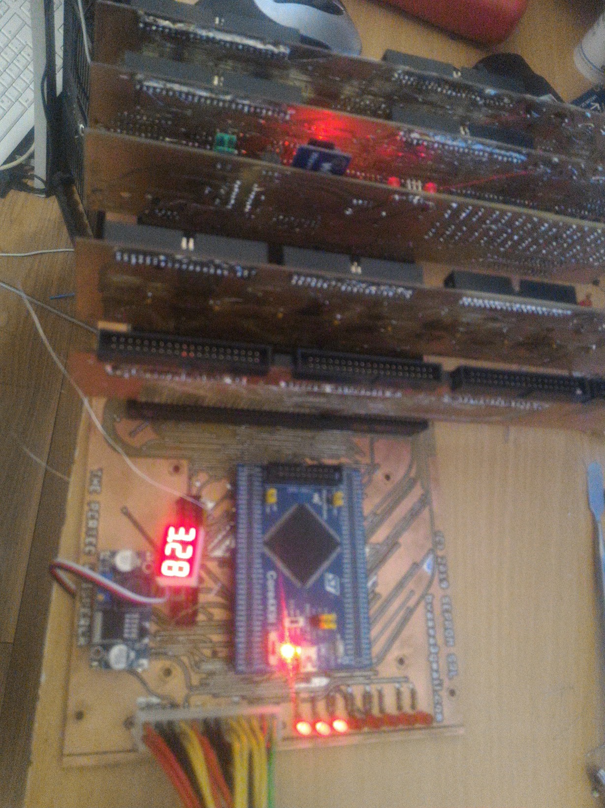
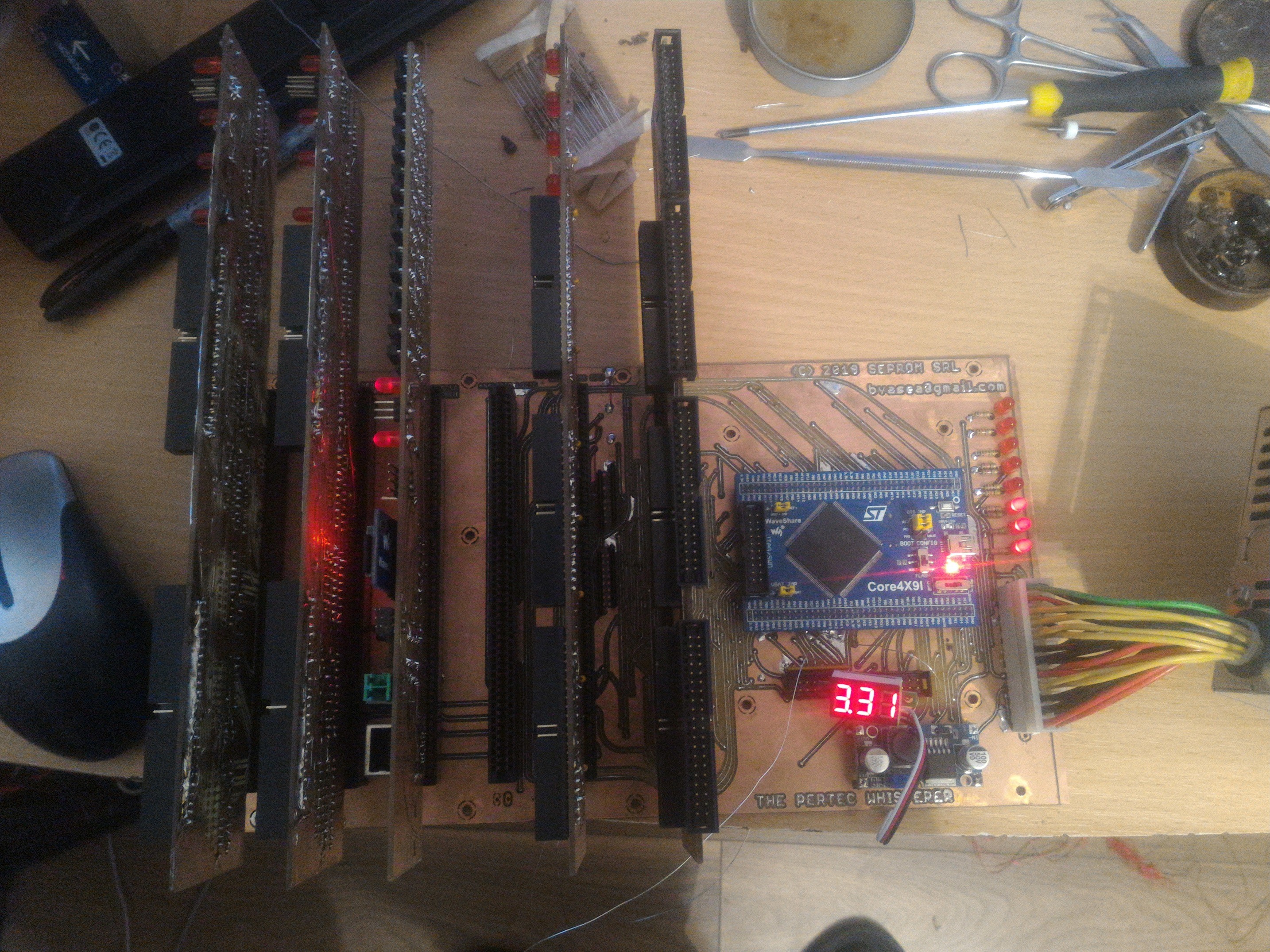
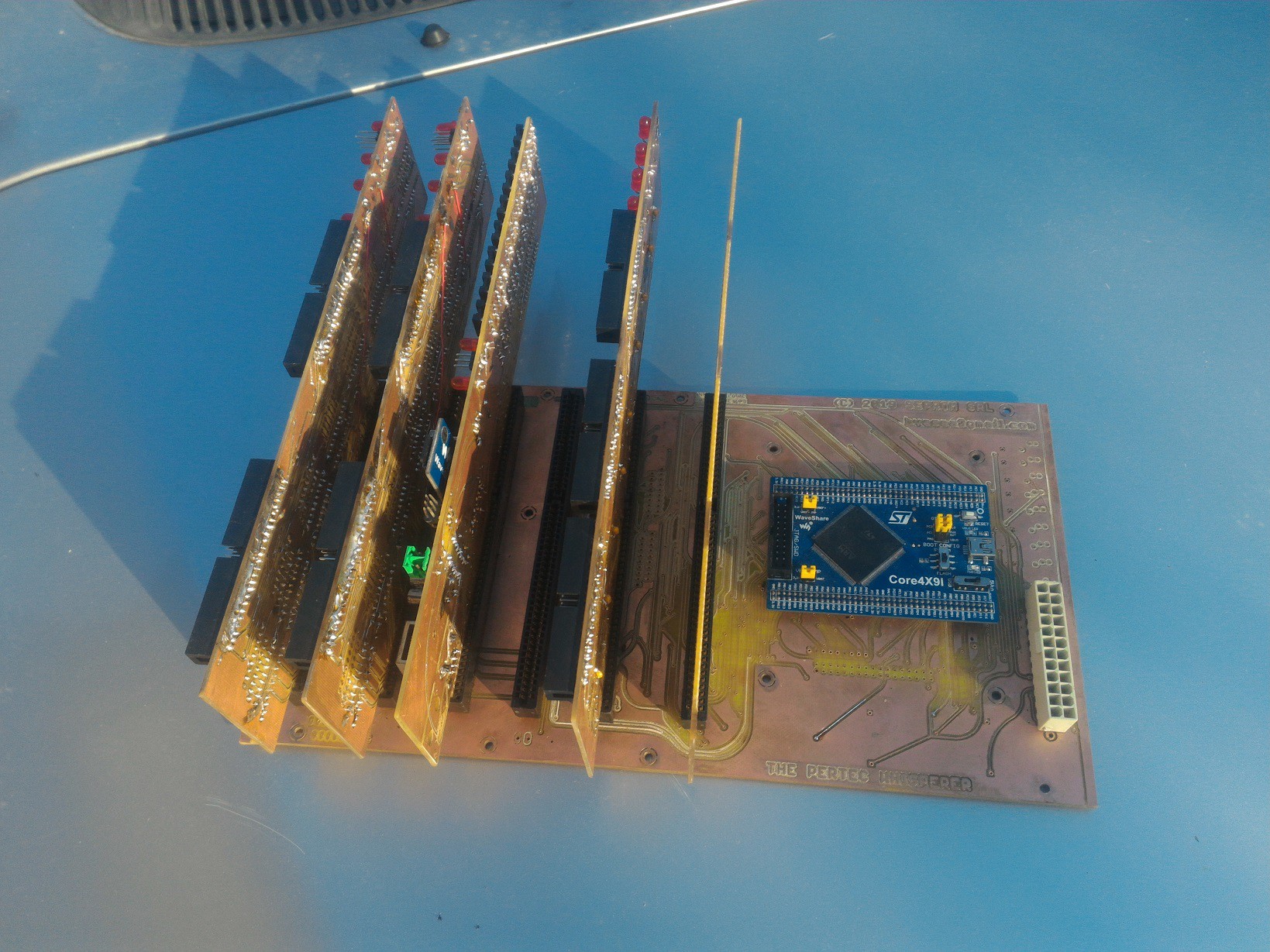
    After some long and busy years:

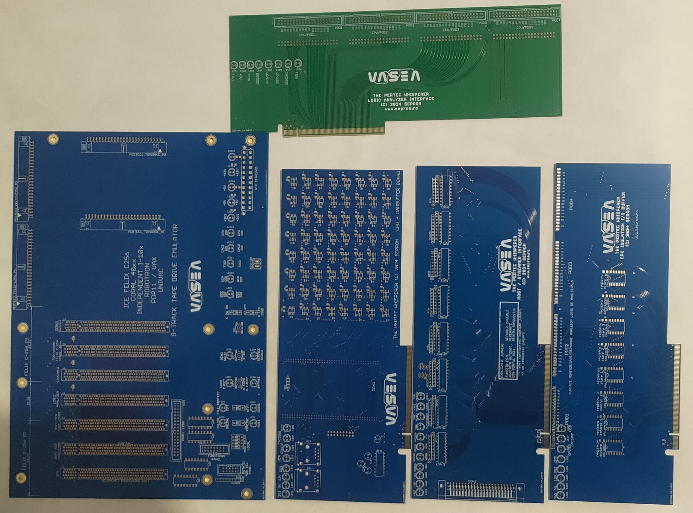
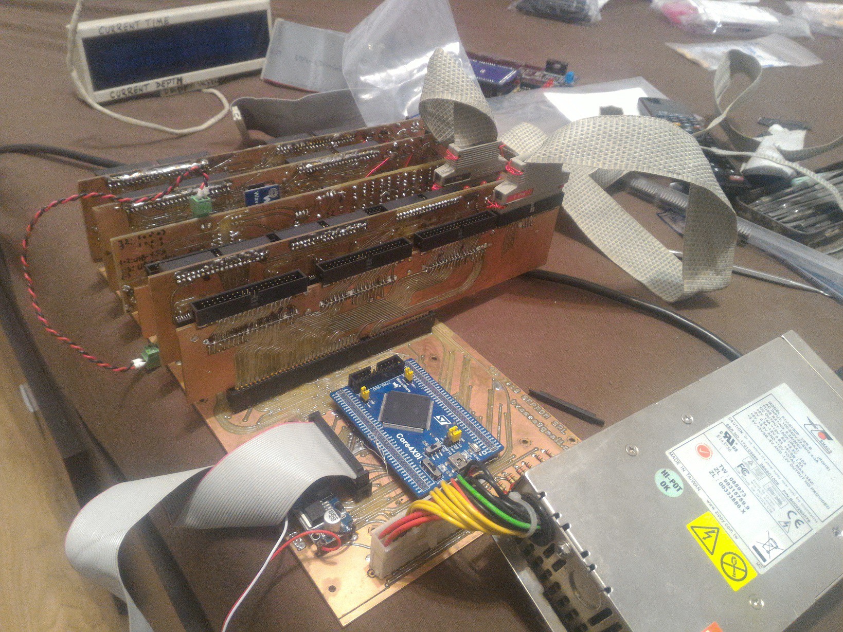
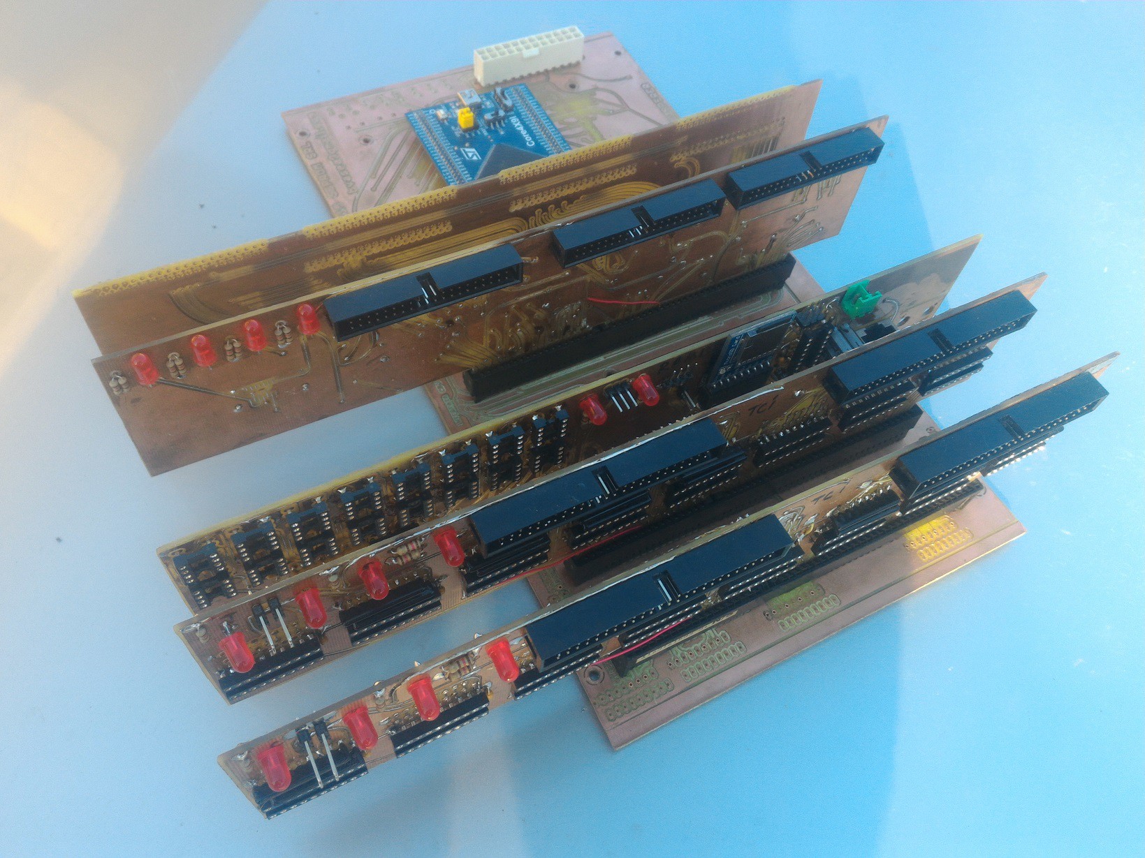
    1. Boards set: 

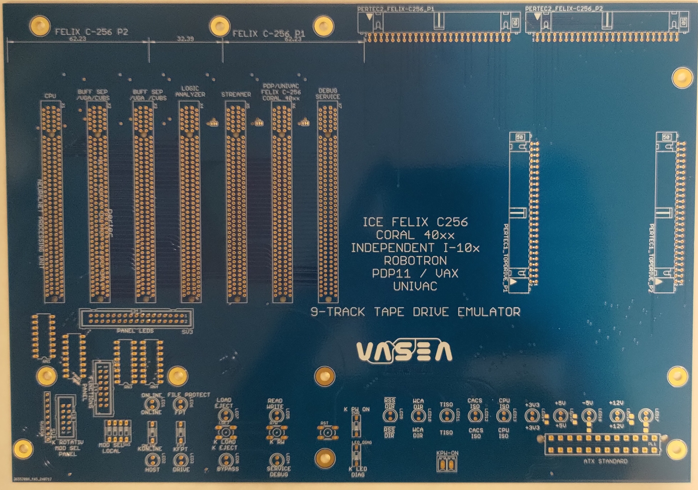
    - mainboard PCIe backplane with custom wirings;

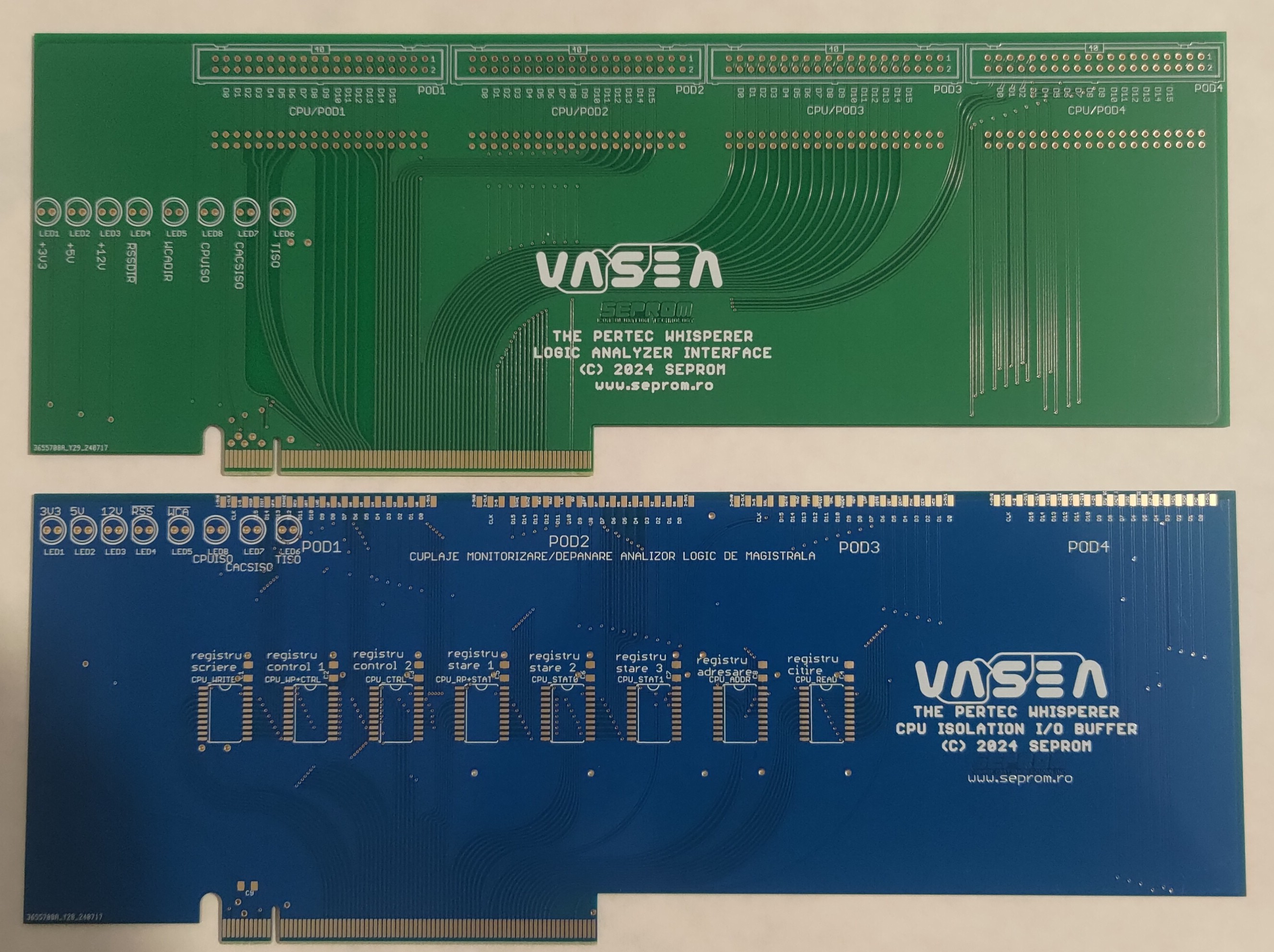
    - logic analyzer interface 1 (green board);

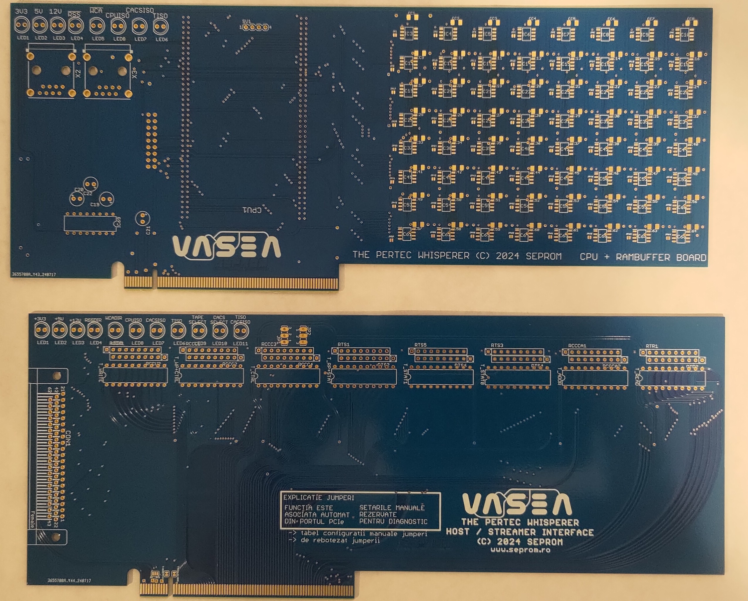
    - CPU + ram buffer + sdcard + serial i/o board (right side of the mainboard);

    - Host/drive i/o interface for mainframe/tape drive;

    - CPU i/o/isolation buffer - right side.

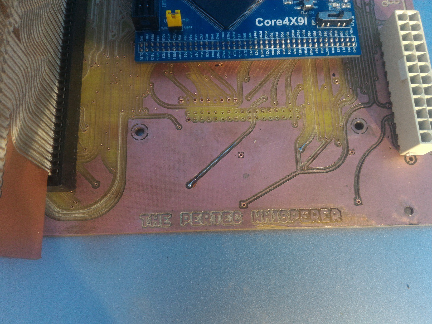
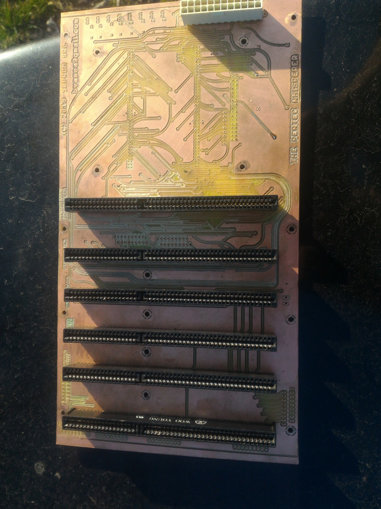
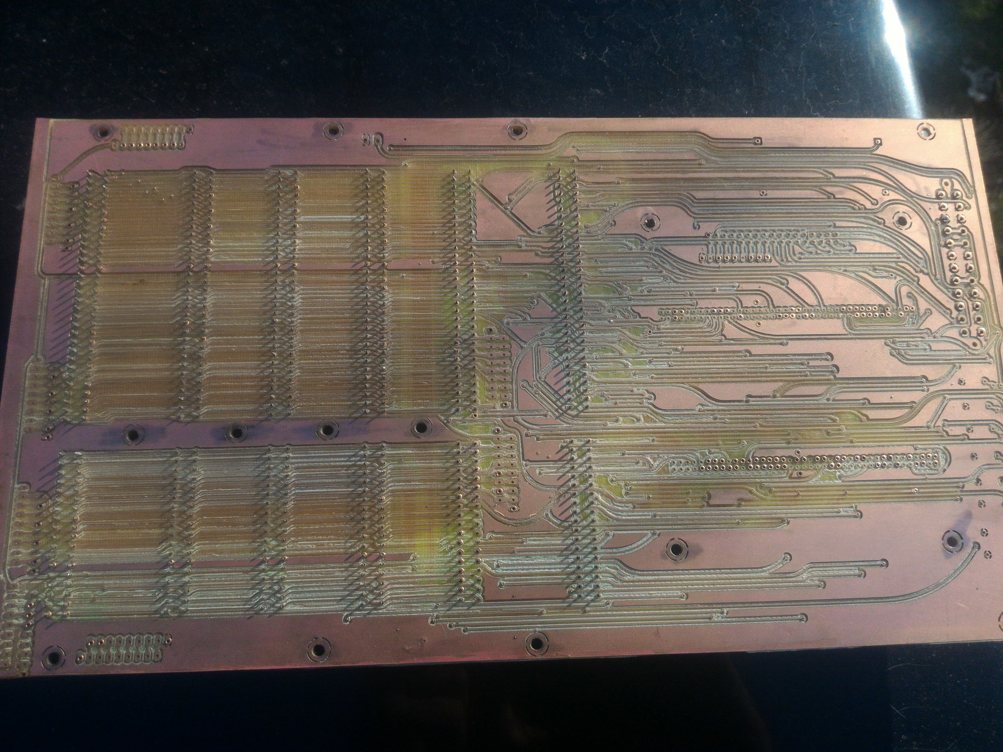
    2. Main board

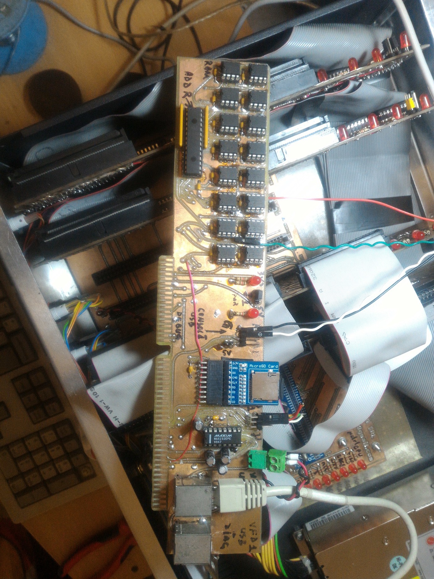
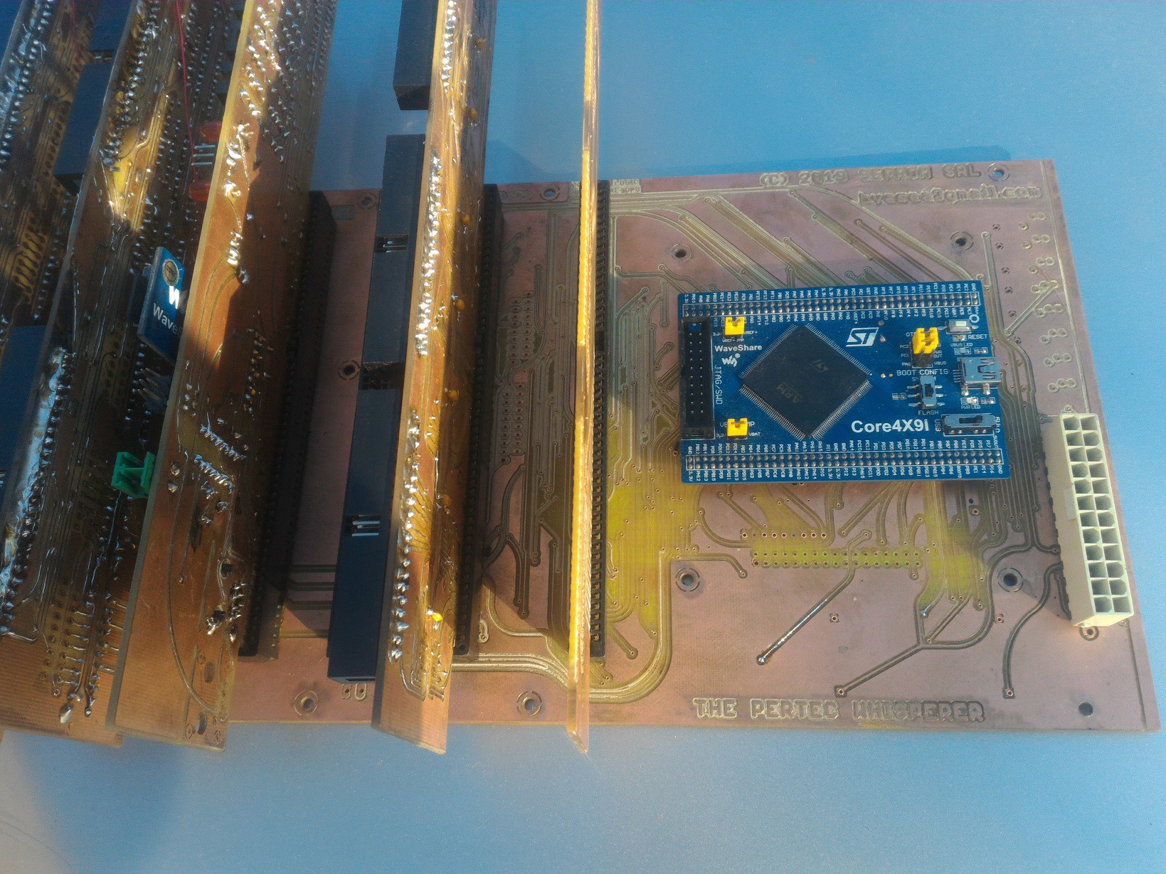
    3. CPU + ram buffer + serial i/o + sdcard i/o (top)

    Tape Drive / mainframe interface (bottom). In the square there are some magic incantations written in the language of Dracula (Romanian), it says like this:  "jumpers explained:  function is automatically associated from the corresponding PCIe port. Manual settings are reserved for diagnosis only.  To be drawn: -> table with manually-configuration jumpers; -> all jumpers to be re-named (actually "re-baptized" with a new name)

    4. Logic Analyzer interface (top, green)

    Isolation buffer (bottom).

    Back into the surgery room.

    Keep in touch.

    [end of transmission]

  • Project video

    [skaarj]06/22/2019 at 10:55 0 comments

    IT WORKS!!!!!!!

  • Whispering in host mode

    [skaarj]06/14/2019 at 15:37 0 comments


    This one was a little tricky to develop so it took some more time than expected. 

    Here is what had to be done:

    1. Establish communication with the tape drive. For this to happen, the following steps are required:

       - select the tape drive using /ITAD lines (transport address 0 and 1);

       - issue a short /IFAD pulse of a few uSecs in order to abort any current interruptible operation the tape drive is performing;

       - issue a short /IREW pulse to make sure the drive stays at BOT;

       - select the data density - 1600 bytes per inch for now: /IWFM+/IEDIT+/IERASE down at the same time,  pulse  /IGO and those three up.

       The tape drive should now issue the following status lines active:

    /IONL  (online)    /IRDY  (ready)   /ILDP  (BOT, begin of tape or load point),  /IFPT (file protect) if manually selected on the drive.

    2. Start the data transfer:

    The data transfer starts when the drive receives a /IGO pulse and the rest is described in the previous chapter - catch /IRSTR, /IDBY, /IFBY and /IFMK using prioritized interrupt lines, fill a 32kB buffer (max buffer size as specified in most of the MsDos pertec drivers), dump it into the SPI RAM Buffer via DMA channel.  Each time the entire 2 MBytes RAM Buffer is filled, the operations are paused, the drive waits for a new /IGO while rewinding at the end of the last read block, in the mean time the entire 2 MBytes RAM Buffer is dumped on the microSD card, cleared and the transfer resumes until 2 x /IFMK or /EOT (end of tape) are signaled.

    3. Store the data either for fun/inspection/museum purpose or for usage in a physical mainframe environment:

      So I have this big chunk of a 40MB 9-track tape drive data dumped inside a microSD card describing some eastern block communist old plans for building the most reliable agricultural tractor in the world. I can either stare at the data - nobody has it in the original format anymore - or I can move things further and load it into a mainframe in order to get access to the top secret development plans.

    For the first variant there is no need to replicate the separation into distinct blocks and filemarks. 

    However if I really want to build my own tractor and take over the fields  in my area, I have to push the things a little further and acquire the blocks and filemarks displacement scheme into a map and replicate them by pulsing the corresponding PERTEC lines on the interface while playing in the DRIVE championship.  

    For various reasons the fatfs library is not capable to handle two distinct files - to store the "map" contents separately. Also the uSD transfer does not work in 4-bit wide bus mode (STM32CubeMX bug) to be able to get things done quickly enough while talking to the drive - good thing I chose to work with a Ram Buffer. 

    And I am not going to sacrifice an 128k RAM bank just for generating a separate map file and get tons of headaches for not being able to store it separately on the SD card.

    4. Welcome to Wonderland:   SIMH Emulator has its own format for handling tape images - thank you Chuck for the tip with SIMH .TAP Format which says each block is preceded and followed by descriptors telling details about the current and previous block. 

    The implemented format looks like this:

    ---------|--------|---------------|--------|---------------|--------|---------------...
    Read more »

  • Mainframes behind the Iron Curtain

    [skaarj]05/04/2019 at 07:23 0 comments

     Hackaday covered a very small number of topics about computing technology behind the Iron Curtain, so here is a fresh hot one: [skaarj]  is rebuilding a Romanian Mainframe (translated link - this is a very old topic and some pictures or references may be missing). Such pieces of communist technology are pretty rare and most of them require excruciating painful hard work to resuscitate. [skaarj] is not entirely sure which mainframe type to chose from the three dinosaurs roaring in Romania's computing centers during those dark prehistoric times:  FELIXCORAL or INDEPENDENT, as the components are pretty rare, in very bad shape and whatever parts he managed to salvage... come from all three types. Due to their proven performances, those three names were a shock for the COMECON market controlled by the Soviet Union, so Big Uncle Bear officially restricted any exports through special directives straight from Moscow. To avoid the typical anger, some government sources explained the decision to Romania's beloved leader due to CORAL and INDEPENDENT performances being far superior to the USA's PDP.

    So far [skaarj] managed to recover three  from a Felix-type mainframe, some parts from a CORAL 4030 mainframe, a broken tape drive from an Independent i-100, a Siemens Sinumerik punched paper tape reader from a Felix-M18 and some various peripherals such as 8" floppy drives, huge hard disks, cassette tape drives or various circuit boards. The clumsy serial terminal called DAF-2020 (Display Alpha Numeric) is already up and running, and through the courtesy of [Nico] the future mainframe will be able to access PERTEC-interfaced peripherals through a PERTEC to SCSI converter. 

    Since the central processing unit (drawer) released its magic smoke in the final agonizing days of the communist regime while running a modified smuggled copy of RSX-11 Operating System, [skaarj] decided to hook a Marvell OpenRD Ultimate Development Platform and install FreeBSD Unix to get access to the functional peripherals and to experiment with ferrite core memory banks. Check the videos on the project main page.

  • RAM BUFFER

    [skaarj]04/19/2019 at 20:28 0 comments

    Data needs to be read fast and precious time is waisted with traditional approach:

    - continuous reading of GPIO ports and wait for them to confirm the data is ready for pick-up;

    - store the byte inside a variable;

    - convert from IBM-style to normal style using either math or a lookup table (faster!), invert the byte

    - append the byte to the end of a string;

    - push each string to microSD card at every end-of-block;

    - try to catch a new read and try not to lose data if all the above tasks together take more than 1.2 microseconds to finish.

    All these operations waist precious time so special measures had to be taken:

    1. Pertec works in inverted logic (0V means true, 5V means false). This allows for long cables and little noise influence but requires special attention at software level, so each buffer contains the Soviet Union equivalent of 74ALS640 / 74ALS642:  the K555AP9.  This inverts the received data - thus saving precious CPU time and also making the programming easier without any software inverted logic.  

    The "normal" circuits were tried first:  

    - non-inverting data output 74LS/ALS/HC/HCT/N/S-245, 74LS/ALS/HC/HCT/N/S-641,;  

    - inverting data output 74LS/ALS/HC/HCT/N/S-640 and 642, both normal and -1N variant (double miliamp output signal intensity) 

    All of them in SMD and THT variants.

     Either I bought a lot of trashed parts from respectable, unquestionable great suppliers - which I seriously do not believe -  or the soviets had a better design because the 'normal' (74-series) circuits caused surges in the power supply unit in bypass and service mode and they became extremely hot. At first I could not believe and I blamed the soviet chips for destroying my tape drives and my Pertec controllers. I developed a theory about black holes feeding on $$, explained later in this text. 

    Anyway - I saved a lot of CPU time by passing all byte-inverting operations to external circuitry.

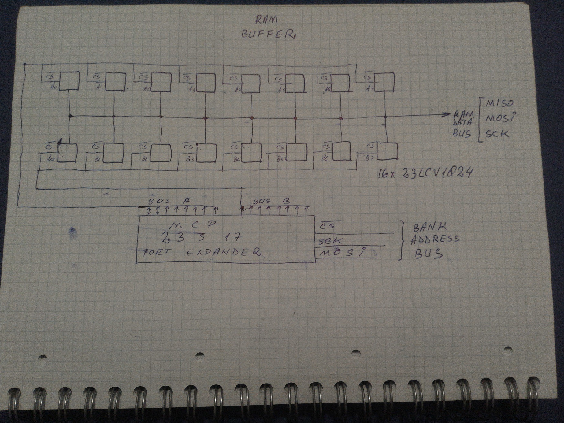
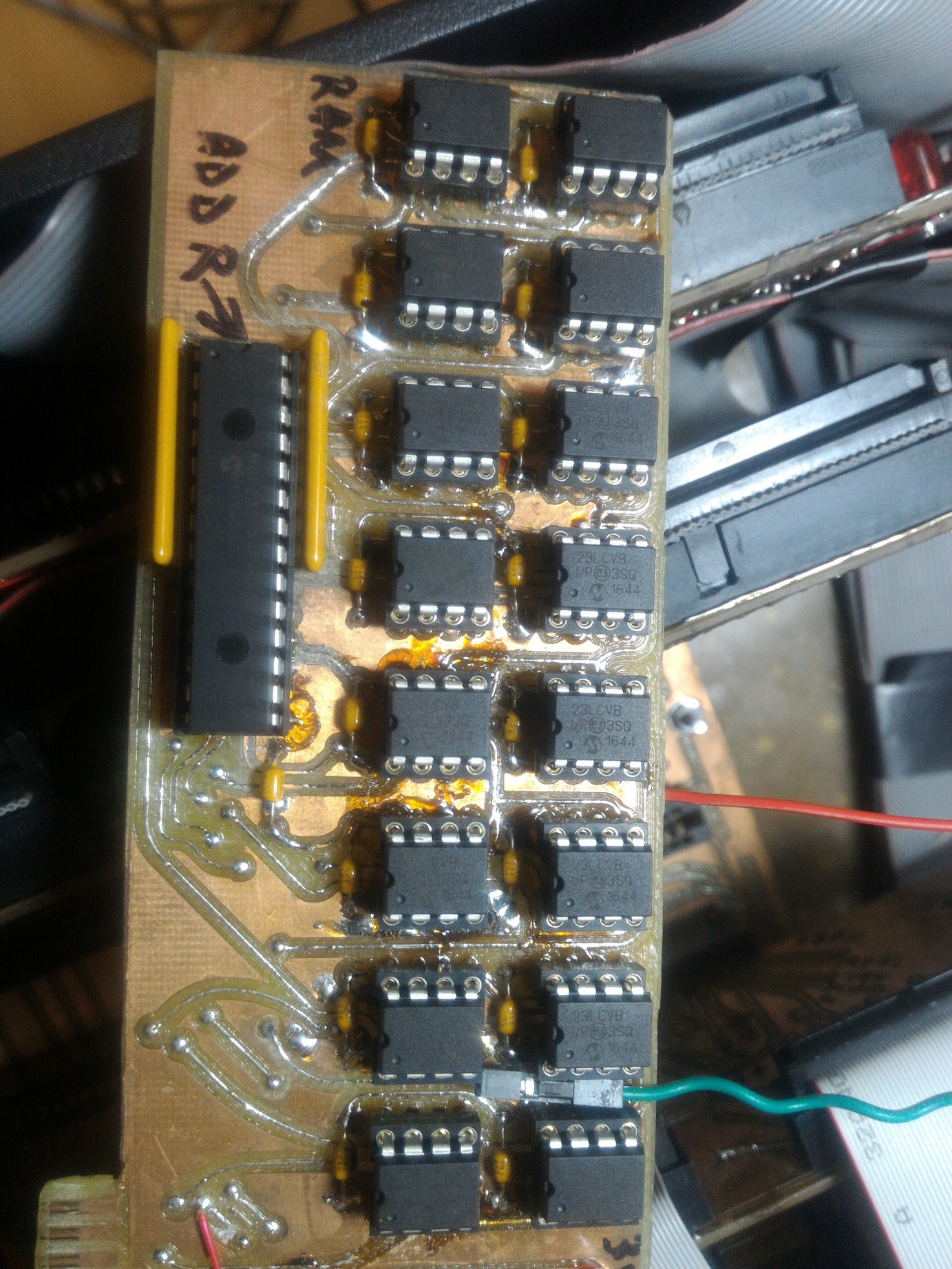
    2. Build a fast ram bank using 16 x 23LCV1024 (128 kBytes) high speed serial SRAM. 

        As a note: I don't use commercial measurement units. They are lies and blasfemies for the technical part:  a Megabit counts stuff to trick people. It is an advertising measurement unit which lies about how great is to see the data rate 8 times bigger, larger and faster than the reality.

     A Megabit is some kind of eye drops Viagra: you drop it in the eyes and see things eight times bigger.   

    A megaByte represents a quantity useful in computing and it is 1/8 of a megaviag..bit. The French are wise - they say "mega-octet" to avoid tricking people and I respect them for that.

    So 23LVC1024 holds 128 kBytes - the great "Megabit" which represents around 9% of a 3.5", 1.44MB floppy disk.

    Using 16 of them I built a 2 MBytes RAM bank with custom addressing control. 

    This is the system RAM buffer + uSD storage + serial communication.

     The addressing is performed via one MCP23S17 SPI Port Expander from Microchip, thus saving 13 i/o pins on the controller side:  16 chip-select + 3 SPI without the PEX,   only 6 SPI pins with the PEX.  More RAM, more port expanders (PEX).  If a lot of RAM, the addressing expanders can be.... selected using another PEX. Or a FPGA logic approach which saves a lot of space, time and speed. It's starting to sound like some $$-absorbing black hole theory.

    3. I also defined two DMA stream channels to get the fastest speed available for these 23LCV1024 - actually they should be called 23LCV128kB...

    Read more »

  • Pertec Interface Signals

    [skaarj]04/19/2019 at 19:17 0 comments

    According to the great Archive stored by Bitsavers and after also consulting this amazing Pertec interface explanation at Sydex Inc., the Pertec interface consists of the following:

    - Connectors:  some times 1 x DB62M - tape drive cable, DB62F controller side, some times 2 x Card Edge (CE)50M - tape drive Pertec formatter or CE50F on the cable  each marked P1 and P2,  J1 and J2.

    Both connectors have almost the same signals. Some drives support all of them, some drives just a part of them.

    The following signals correspond to all 1/2" 9-track tape drives with densities of 1600 Bytes per Inch (BPI), 3200BPI and 6250BPI, both Phase Encoding and Group Coded Encoding methods:

    /* test write  IW0....IW7
                                [W7] [W6] [W5] [W4] [W3] [W2] [W1] [W0]  
                         15  14  13  12  11  10   9   8   7    6    5    4    3    2    1    0
             PB   0   0   0   0   0   0   0   0   0    0    0    0    0    0    0    0
      [WRITE]                                 X    X    X    X    X    X    X    X
     [WRMASK] 1   1   1   1   1   1   1   1   0    0    0    0    0    0    0    0
        WRMASK = 0b1111111100000000 = 0xFF00;
    */
            
    // Write lines - IBM-style ordering, meaning Bit 0 = MSB, 
    // Bit 7 = LSB
    
    /*   test IWP   PB8
                                        [WP]
             15  14  13  12  11  10   9   8   7   6   5   4   3   2   1   0
         PB   0   0   0   0   0   0   0   0   0   0   0   0   0   0   0   0
     [IWP]                                X   
     [WRMASK] 1   1   1   1   1   1   1   0   1   1   1   1   1   1   1   1
    
    WPMASK = 0b1111111011111111 = 0xFEFF;
        
    */
    // IWP  Write parity - odd parity computed over IW0–IW7 
    // and on some drives is ignored and computed by the formatter.


    // CONTROL SIGNALS
    // Activated by the controller/mainframe side - operations 
    // for the drive to execute
    
    /* test CTRL0  PB9...PB15 
           HISP EDIT WFM ERASE REV  WRT LWD
             15  14   13  12    11  10   9   8   7   6   5   4   3   2   1   0
         PB   0   0    0   0     0   0   0   0   0   0   0   0   0   0   0   0
      [CTRL0] X   X    X   X     X   X   X                
     [C0MASK] 0   0    0   0     0   0   0   1   1   1   1   1   1   1   1   1
        C0MASK = 0b0000000111111111 = 0x1FF
    */
    
    #define ILWD    0x200  //  Last word—Used to tell drive that this is 
                           // the last word (byte) to be written 
                           //  in this record, Must be asserted at least 
                           // 300 nsec. before trailing edge of final 
                            //  IWSTR pulse.  
                                         
    #define IWRT 0x400   // Write — When asserted with IGO begins a write sequence.
    
    #define IREV    0x800   // Reverse — When asserted, indicates operation is 
                            // to be performed in the reverse direction.
                                            
    #define IERASE 0x1000 // Erase—When asserted with IWRT and IGO, 
                          // causes tape to be erased, usually for a
                          // predetermined length. Usually used to 
                          // recover from write errors or provide extra 
                          // space for mode changes (Read after write).
                                                
    #define IWFM 0x2000   //  Write filemark; When asserted with 
                          // IWRT, writes a filemark.
    
    #define IEDIT 0x4000  // Edit—Not implmented on all drives.
                          // modifies/updates records inside tape files.
    
    #define IHISP 0x8000  // High speed select—When asserted 1 µsec. before 
                          // and then with IGO (de-asserted any time after 
                           // the trailing edge of IGO selects high-speed 
                            // (streaming) mode.
    
    /*
      test CTRL1  
                                                   RTH1 RTH2 REW RWU LOL GO  
            15  14  13  12  11  10   9   8   7   6   5   4   3   2   1   0
        PC   0   0   0   0   0   0   0   0   0   0   0   0   0   0   0   0
    [CTRL1]                                          X   X   X   X   X   X
    [C1MASK] 1   1   1   1   1   1   1   1   1   1   0   0   0   0   0   0
    [C1MASK = 0b1111111111000000 = 0xFFC0
    */
    
    //CTRL1:
    
    #define IGO   0x01  // Initiate command—Pulsed low for at least 1µsec. 
                        // to start command execution. The formatter address 
                        // lines must be stable throughout the pulse and 
                        // until IFBY drops.
                                            
    #define ILOL  0x02  // Load on-line—Pulsing this line at least 1µsec. 
                        // begins the tape load sequence on many drives.
    
    #define IRWU  0x04 //  Rewind and unload—A pulse of at least 1 µsec. 
                        // initiates a rewind-with-unload and sets
                       // drive offline. Some drives require that IREW is 
                       // also asserted.
                                            
    #define IREW  0x08 // Rewind—A pulse of at least 1 µn;sec. starts the 
                       // tape rewind sequence. Completion is 
                // // signalled by IRWD and IRDY being asserted by the drive.
                                            
    #define IRTH2 0x10 //  Write density select 2—On some drives, this signal, 
                       // along with IRTH1 is used to 
                       // select the drive write density. If it is implemented, 
                       // it is valid only at BOT and must be asserted with IGO 
     // during the...
    Read more »

  • Concept design drawings

    [skaarj]04/19/2019 at 17:51 0 comments

    Short as usual:

    The camera is a little scratched by claws from either pussycats, bats, vampires, hedgehogs, lizards and vacuum tubes but the picture is clear enough for some explanations.

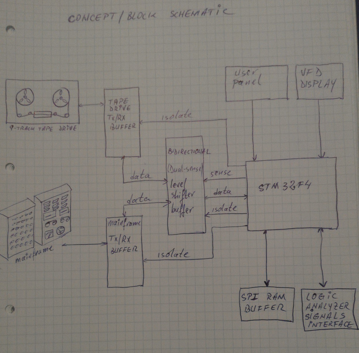
    The system acts like the 'man in the middle' concept. It is connected between the tape drive and mainframe computer - one i/o buffer for each one.

    The STM32 microcontroller is also connected by another bidirectional buffer which also acts as a level shifter.  Datasheet for STM32F429 says the GPIOs are 5V tolerant but I do not want to risk.  There is a microSD card connected to the STM32 but not shown in the schematic above.

    Each buffer can be activated or switched to high impedance state - meaning the corresponding equipment is isolated.

    Commands are selected from the user panel, information is displayed on the VFD and additional debugging service-mode data is available through a serialUSB line.

    The following functions are supported:

    1. Host mode:    tape drive buffer is activated, mainframe buffer is isolated, the STM32 level shifter buffer has write+control lines as outputs and read+status lines as inputs;

    2. Drive mode:  tape drive buffer is switched to high impedance state as we don't need to talk to the drive. Mainframe buffer is activated and the STM32-buffer has write+control lines as inputs (accepting data) and read+status lines as outputs (transmitting data);

    3. Bypass mode:   tape drive and mainframe buffers are both activated and they can talk to each other while the logic analyzer is eavesdropping on the love story flowing through the data bus. The STM32 level-shifter buffer separates the microcontroller from the rest by switching to high-impedance mode.

    4. Monitor/service mode:   all debugging stuff is activated and slowing down the system. Either bypass, host or drive modes are monitored to help debug i/o glitches or software bugs.

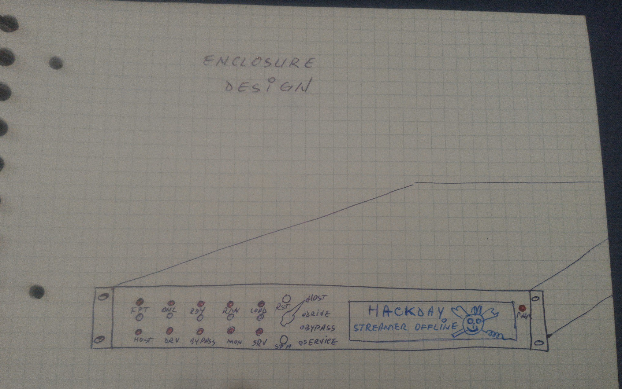
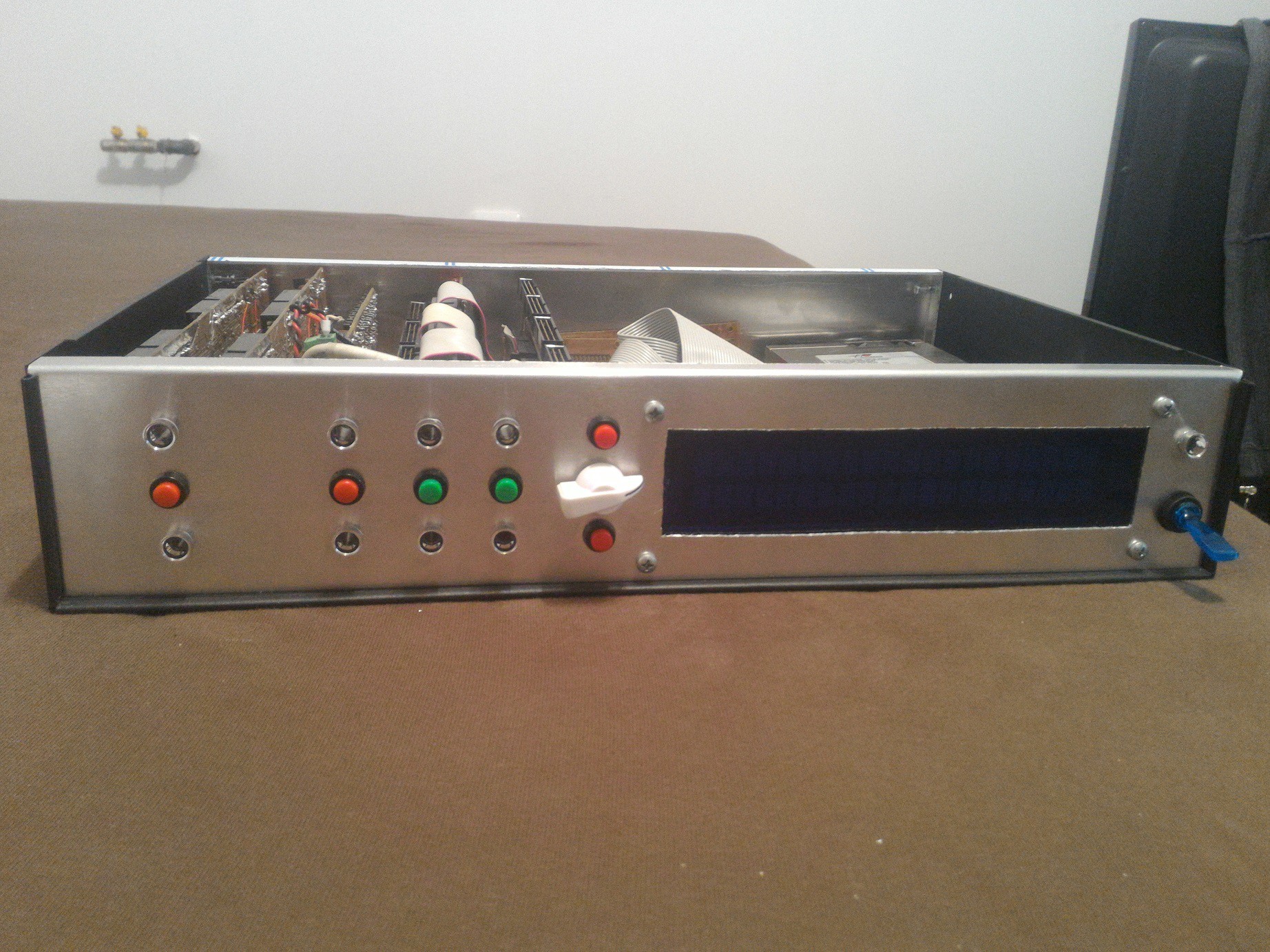
    Everything fits inside a 4-U rack mounted box just like this:

    [END OF TRANSMISSION]

  • Jack in the Box

    [skaarj]03/26/2019 at 20:29 1 comment

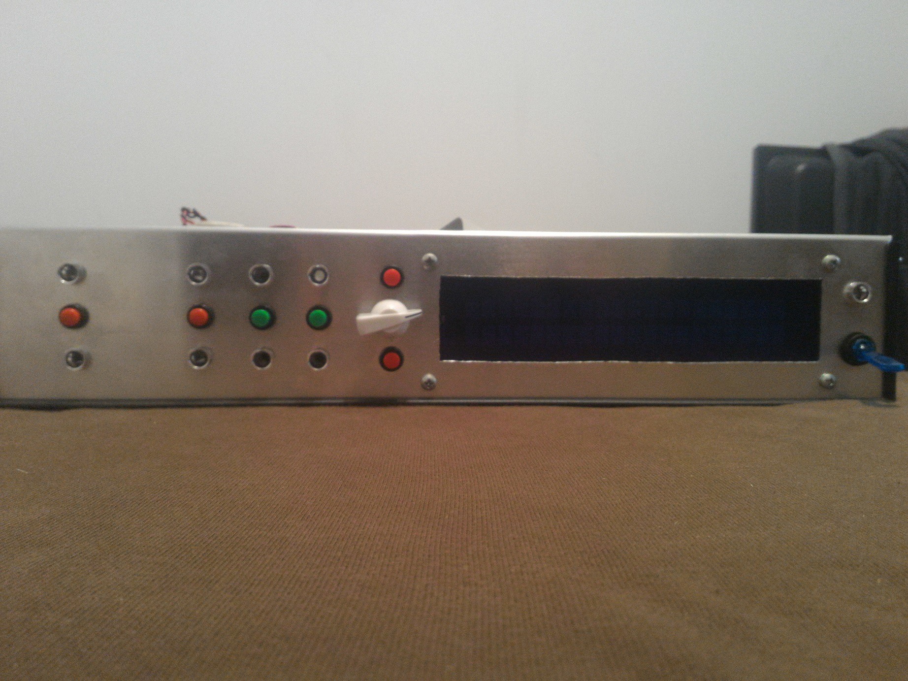
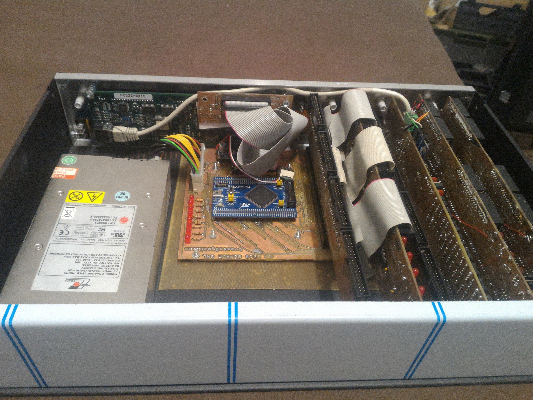
    As a result of my witchcraft activity, the new experimental whispering spell needs a place to enclose its powers while performing its magic. It also needs a screen and some buttons to have fun with.

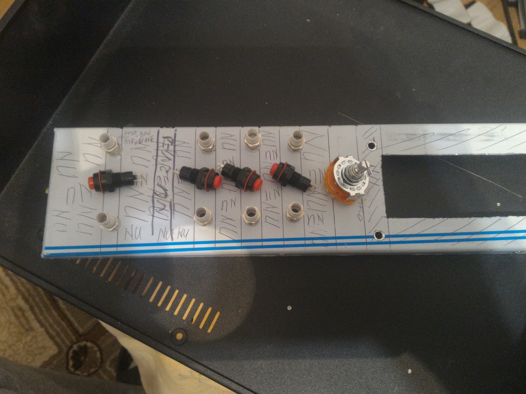
    Of course the back side of the leds and buttons must not overlap the peripheral boards.

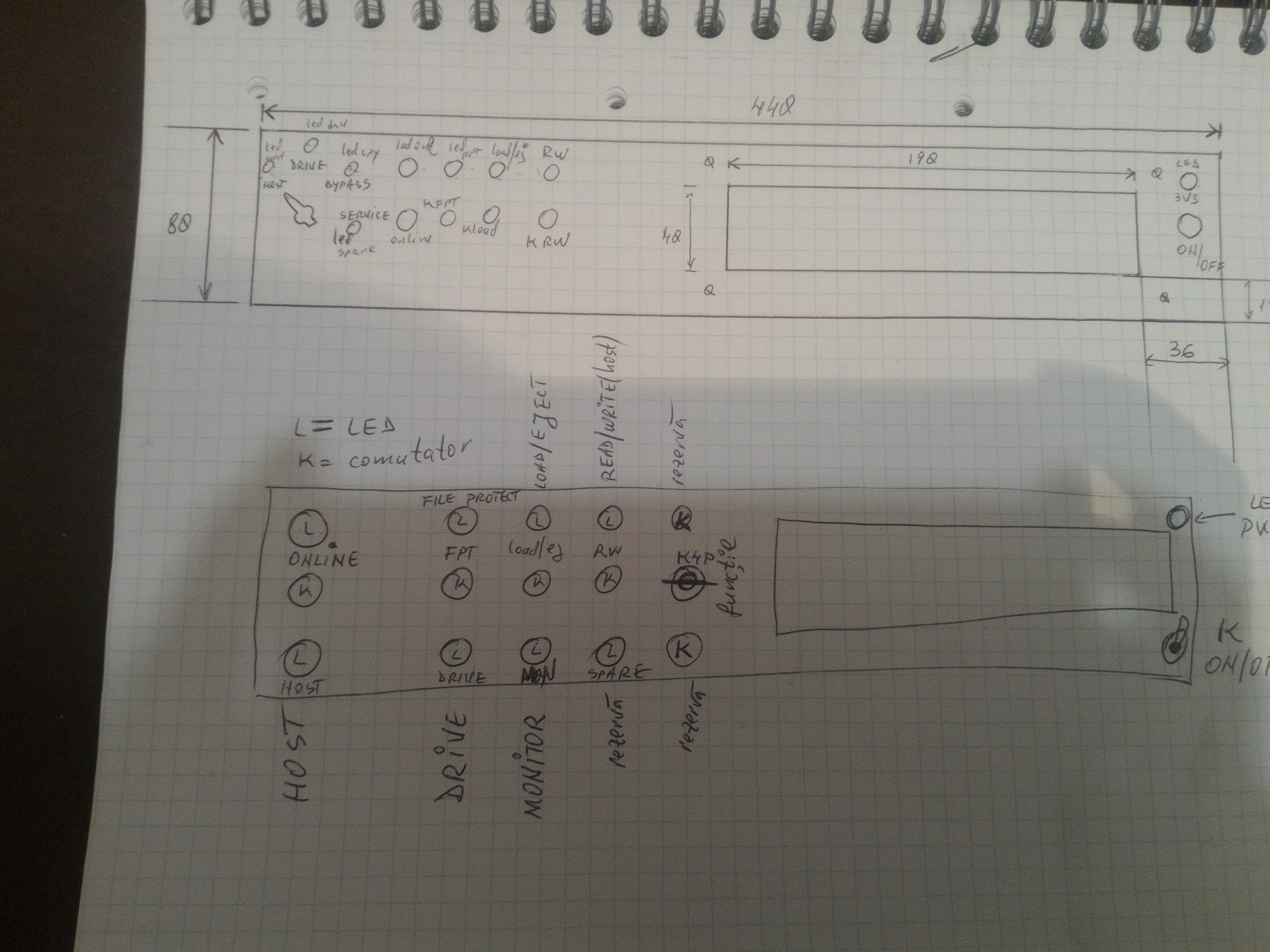
    I tried many arrangements and the last one (bottom) is the final design.

    Some words are in Romanian because the ancient tongue spoken by many warriors and vampires has strong magic powers especially when swearing, and spell radius&effect increase when the finest of the finest beers arrive at the local shop.

    From top-left to right:

    L is LED,  K is button. 

    Online, File Protect, Load/Eject, READ/WRITE, the "K4P" means button with 4 positions which selects the functions.

    Bottom leds:

    Functions: Host mode, Drive mode, Monitor mode, the "spare" is now Bypass mode and the last button (K) on the right is no longer connected, just like the button above K4P.

    Right side of the screen:  top - power-on LED,  bottom - on/off switch.

    Not bad for a manually processed 4U rack-mounted enclosure. The brackets are not installed yet.

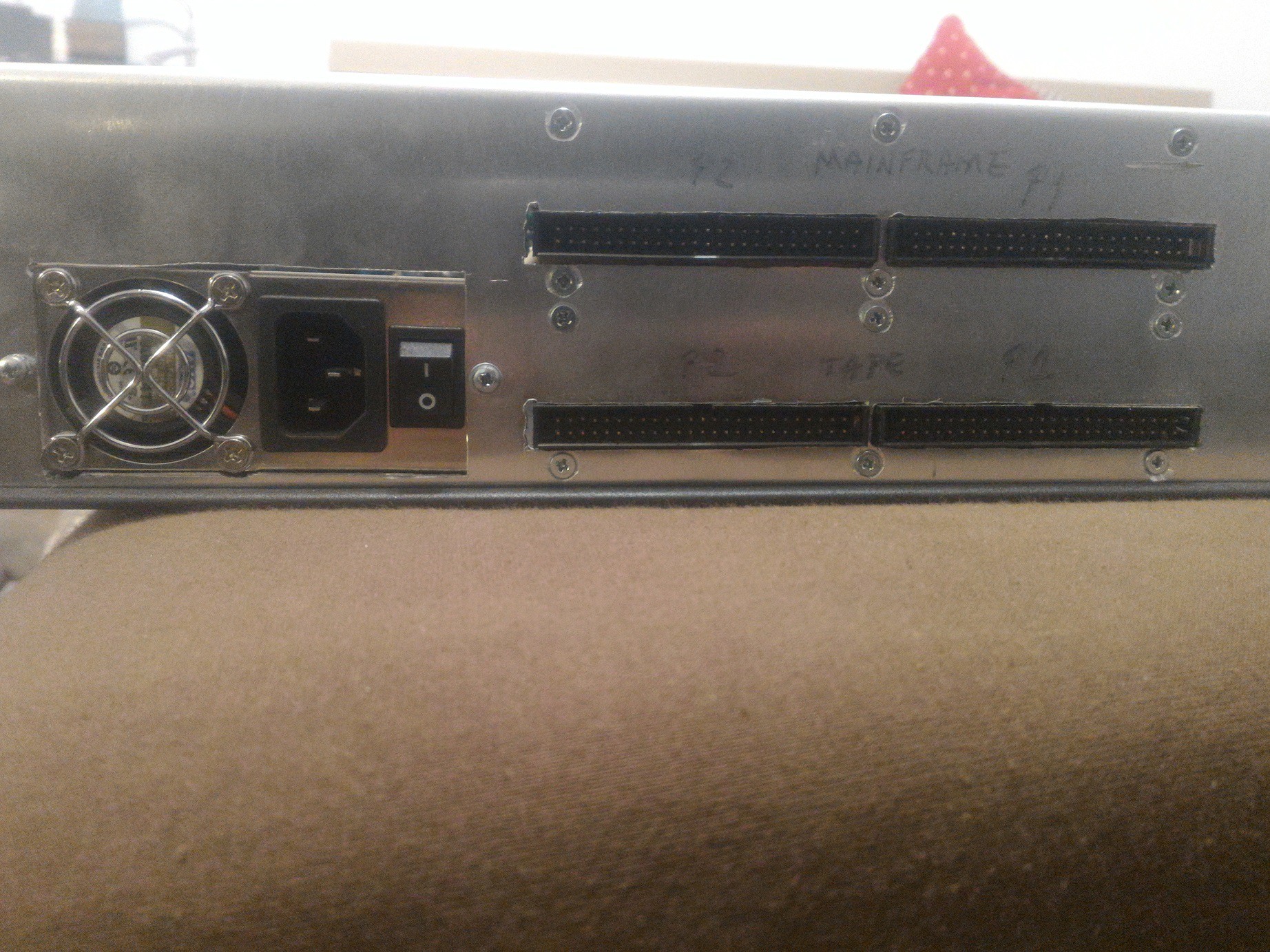
    Both mainframe and tape drive need two connectors. This is the Pertec interface: the greatest pain of the PDP-era. There is no acknowledgement between the host and the drive. The data is just.... "roared" through the bus and the circus training is performed using status and control line jugglery.  On software side there's a lot of logic operations - a great exercise for the neurons.

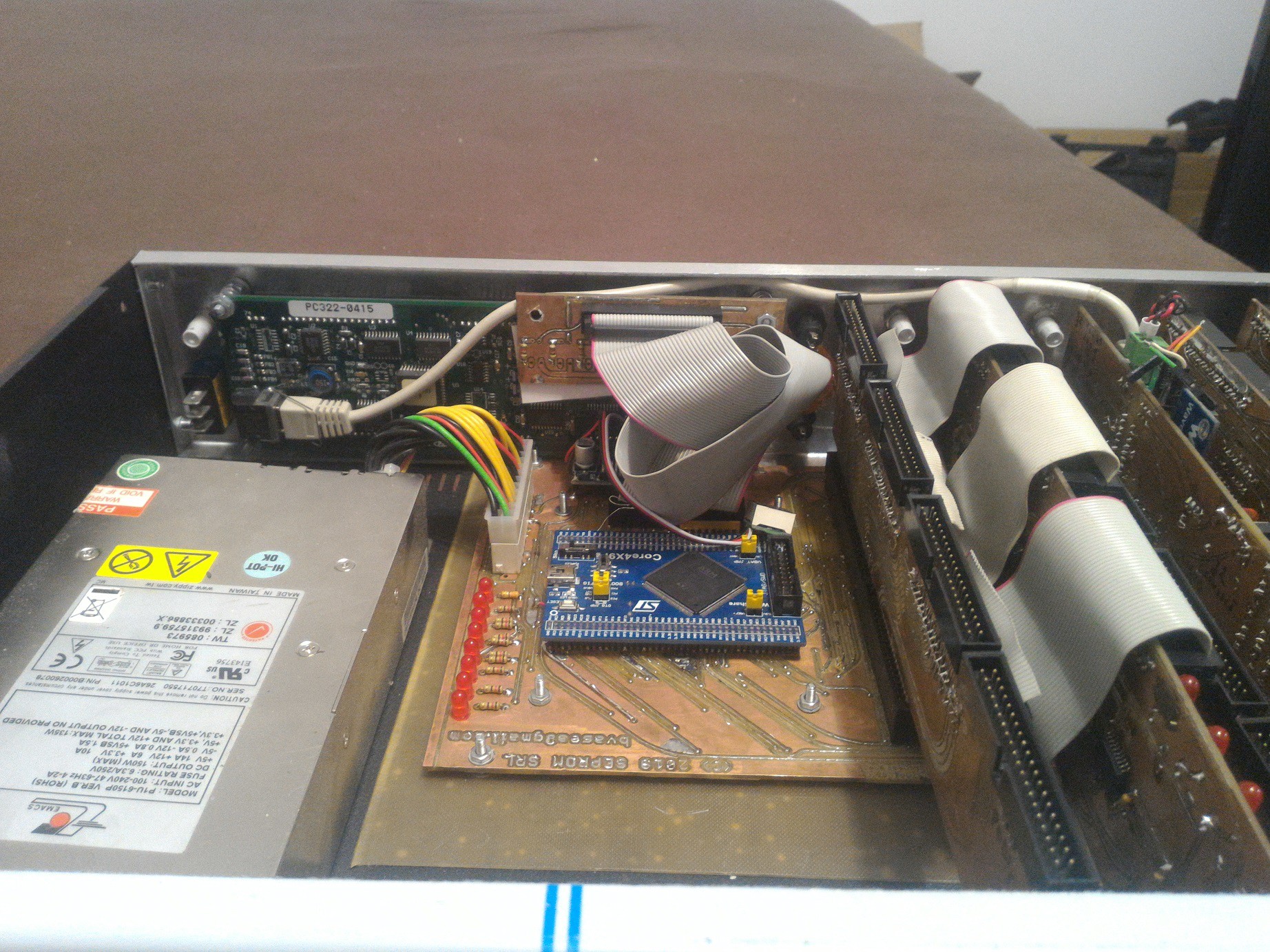
    Pictures from inside:

    from left to right:

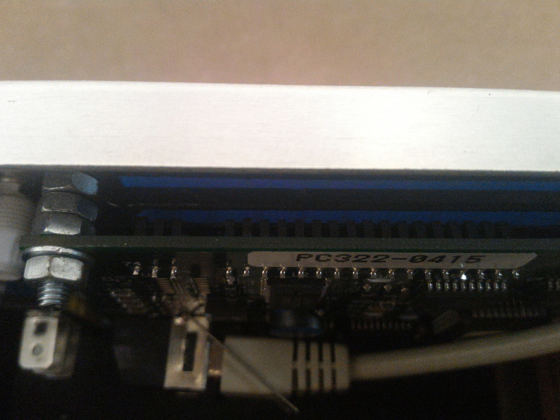
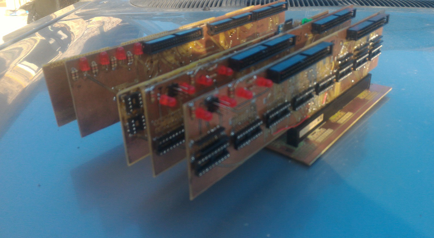
    ATX PSU,  STM32F4 CPU board, CPU interface to buffer (has 4 x IDC40 connectors on top),  CPU Buffer, Bus interceptor (4 x IDC40 on top), rambuff+comms, mainframe buffer, tape drive buffer.

    Display via an old POS 2x20 VFD with 9600 baud serial line.
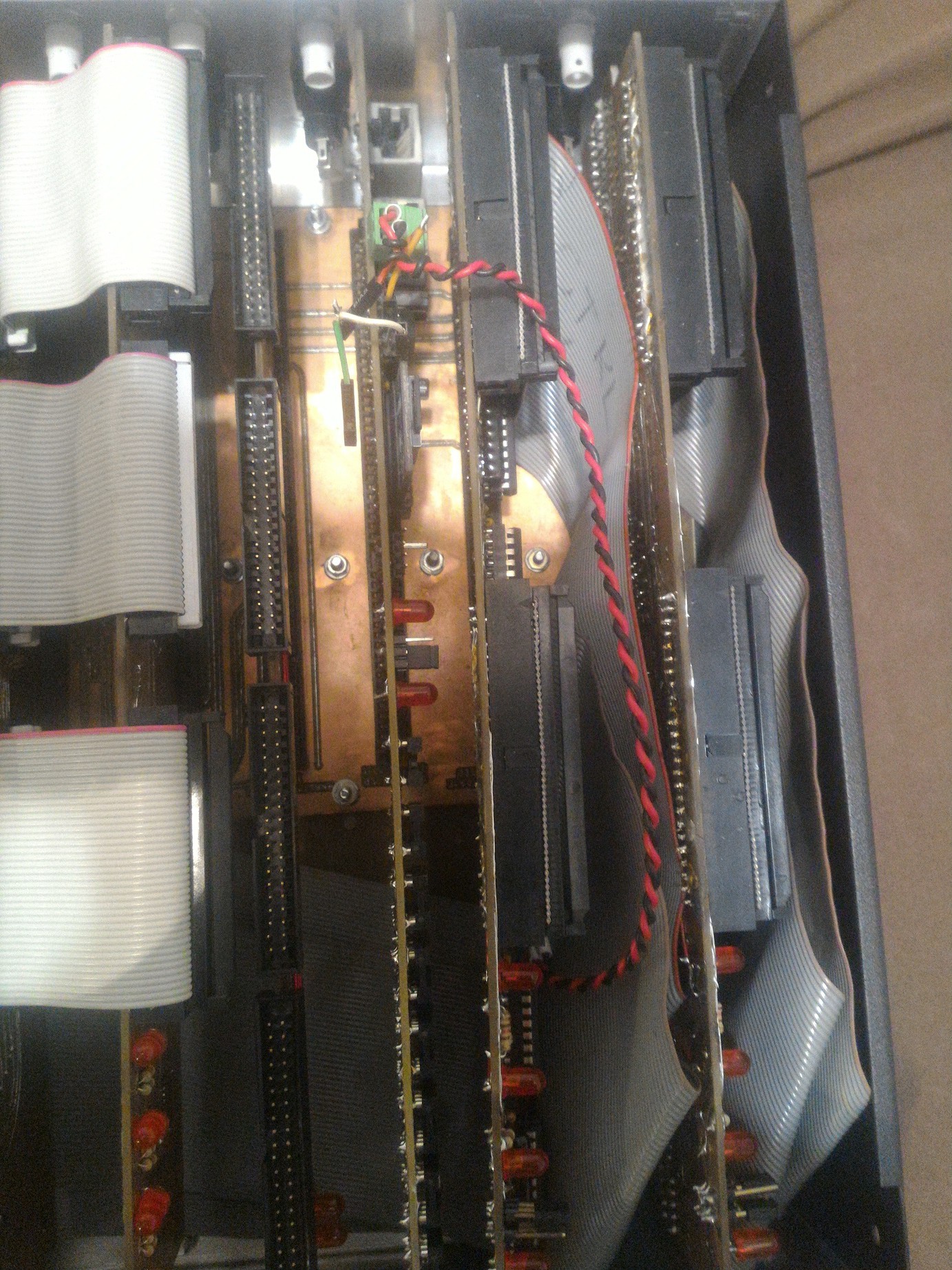
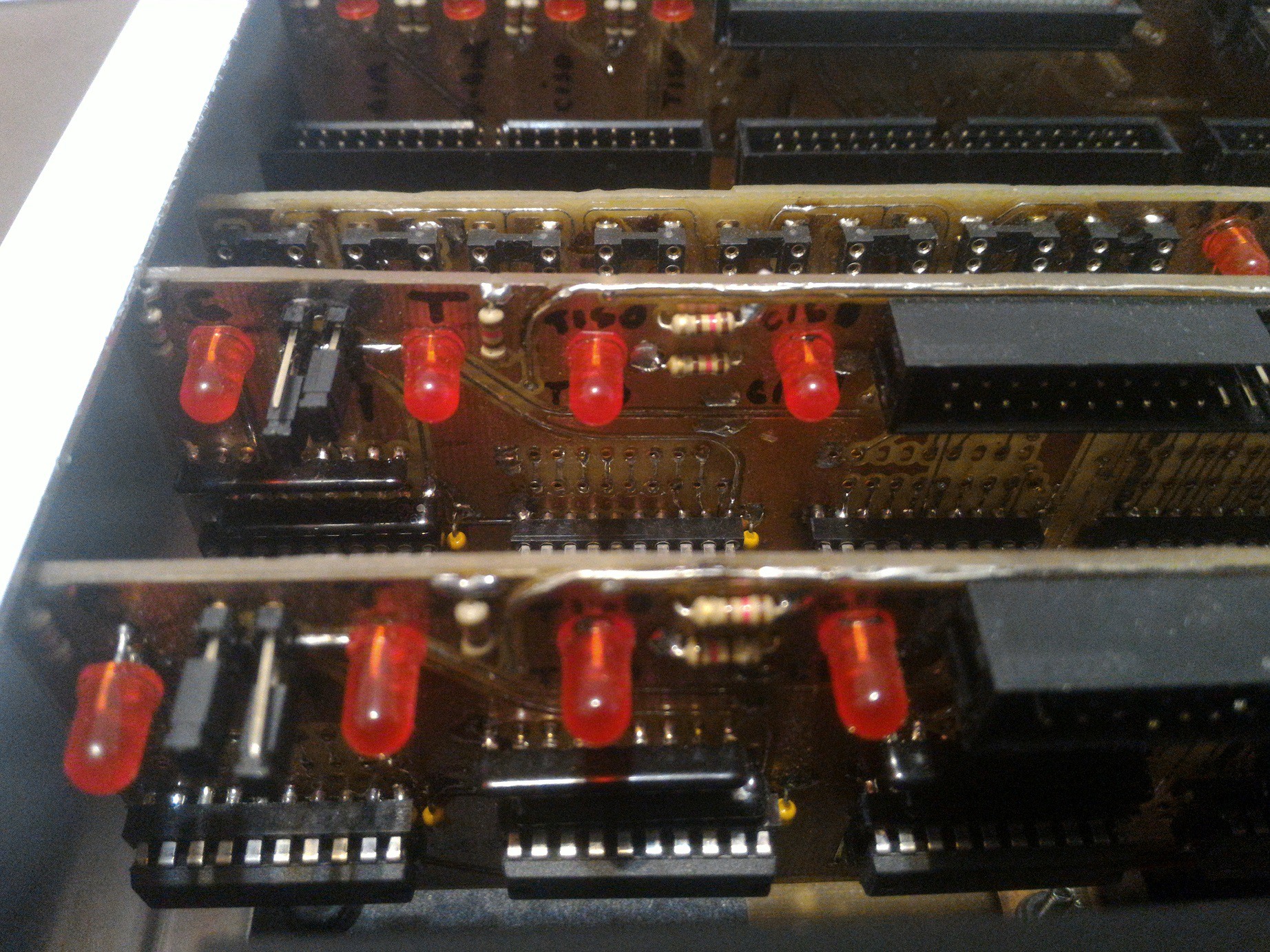
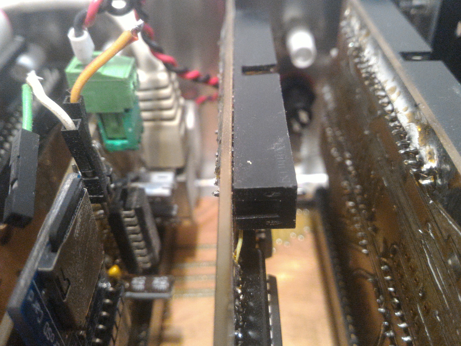
    The edge-mounted IDC40M connectors helps me watch the magic flow using the HP1662 logic analyzer.

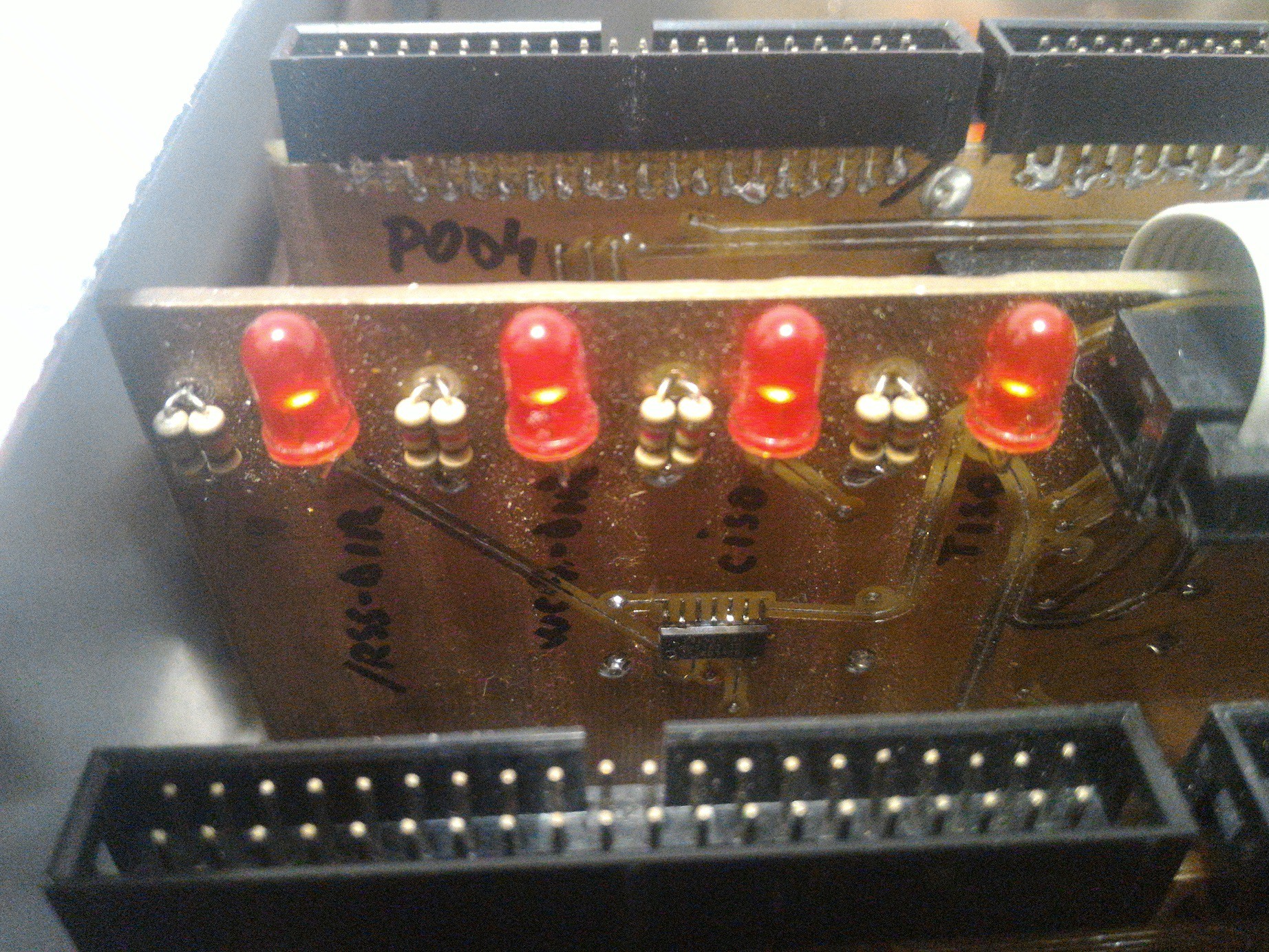
    TISO:   tape isolate;   CISO:  controller (mainframe) isolate.

    /RSS-DIR:  Read-StatuS direction - it changes between host and drive mode;

    WCA-DIR:  Write-Control-Address direction - also changes like above.

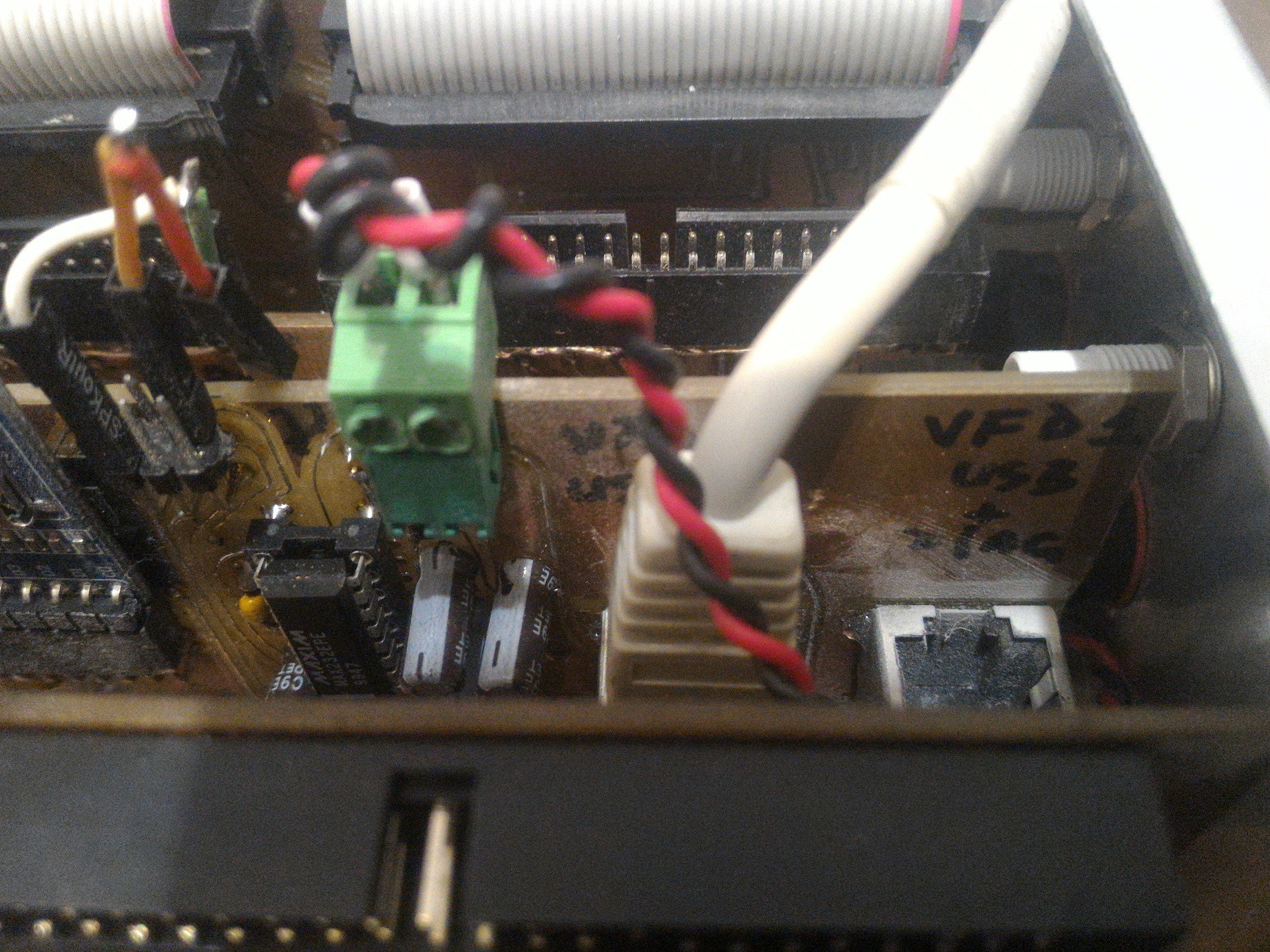
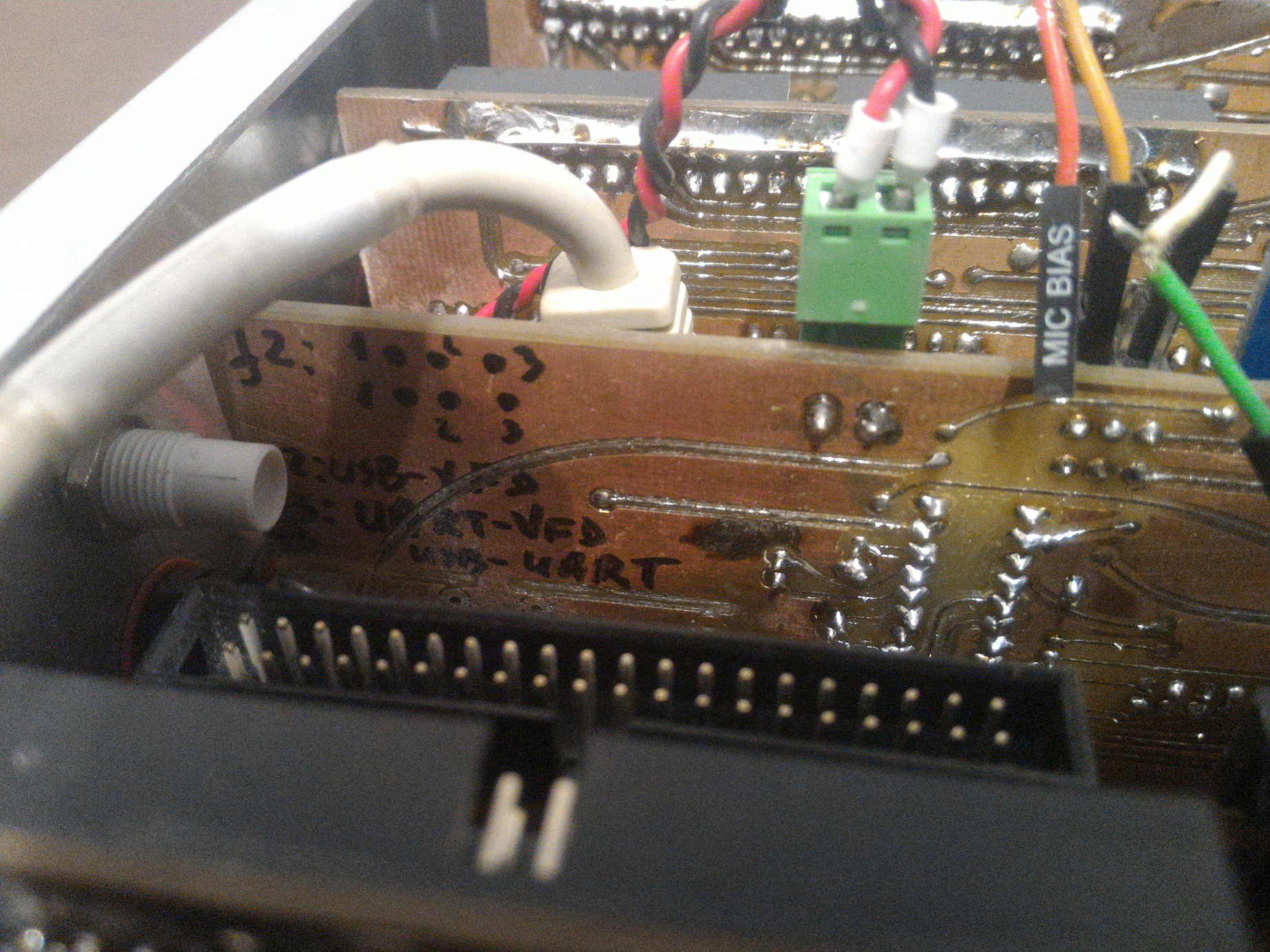
    Close-up view of uSD card module, the MAX232 and the RJ45 serial VFD connector

    There is a second RJ45F on the board. The second VFD is used as a debug console when I am too lazy to connect the serial line to another PC.

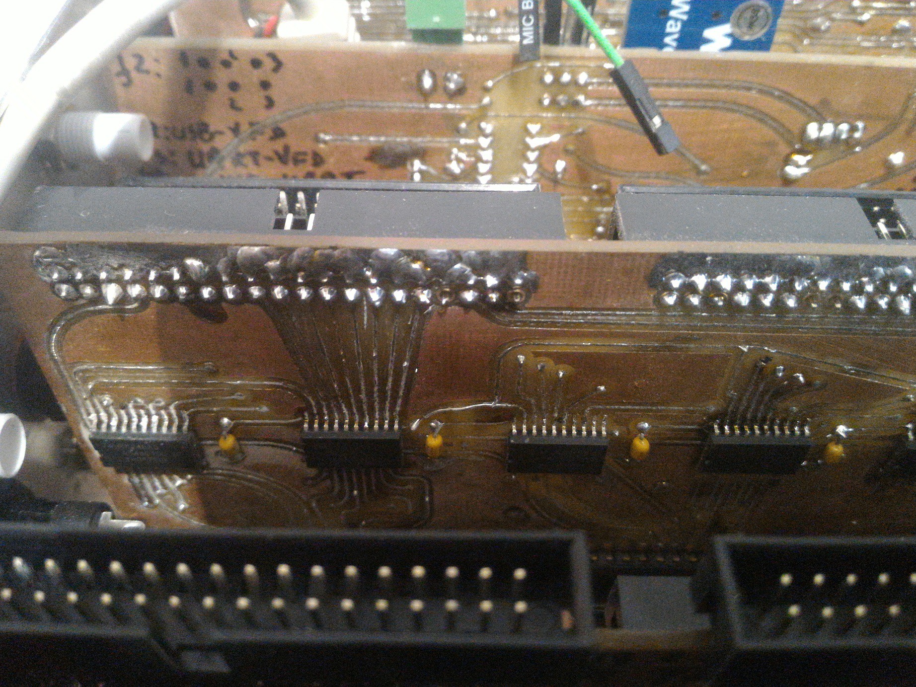
    Close view of the micro controller i/o buffer. This is bidirectional and it also serves as a 5V to 3.3V level shifter.

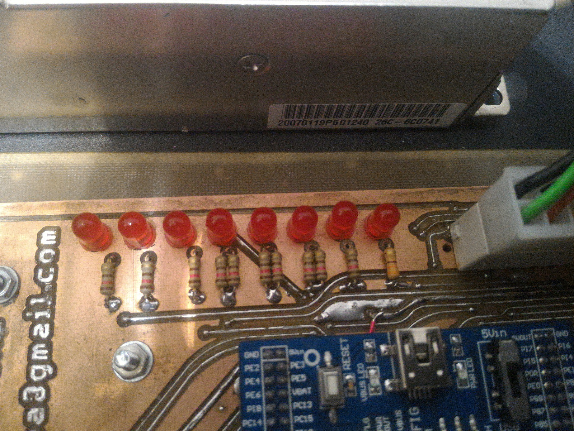
    Status leds. From left to right:  

    mainframe_isolate, rss_dir, wca_dir, tiso, ciso, 3v3, 5V, 12V.

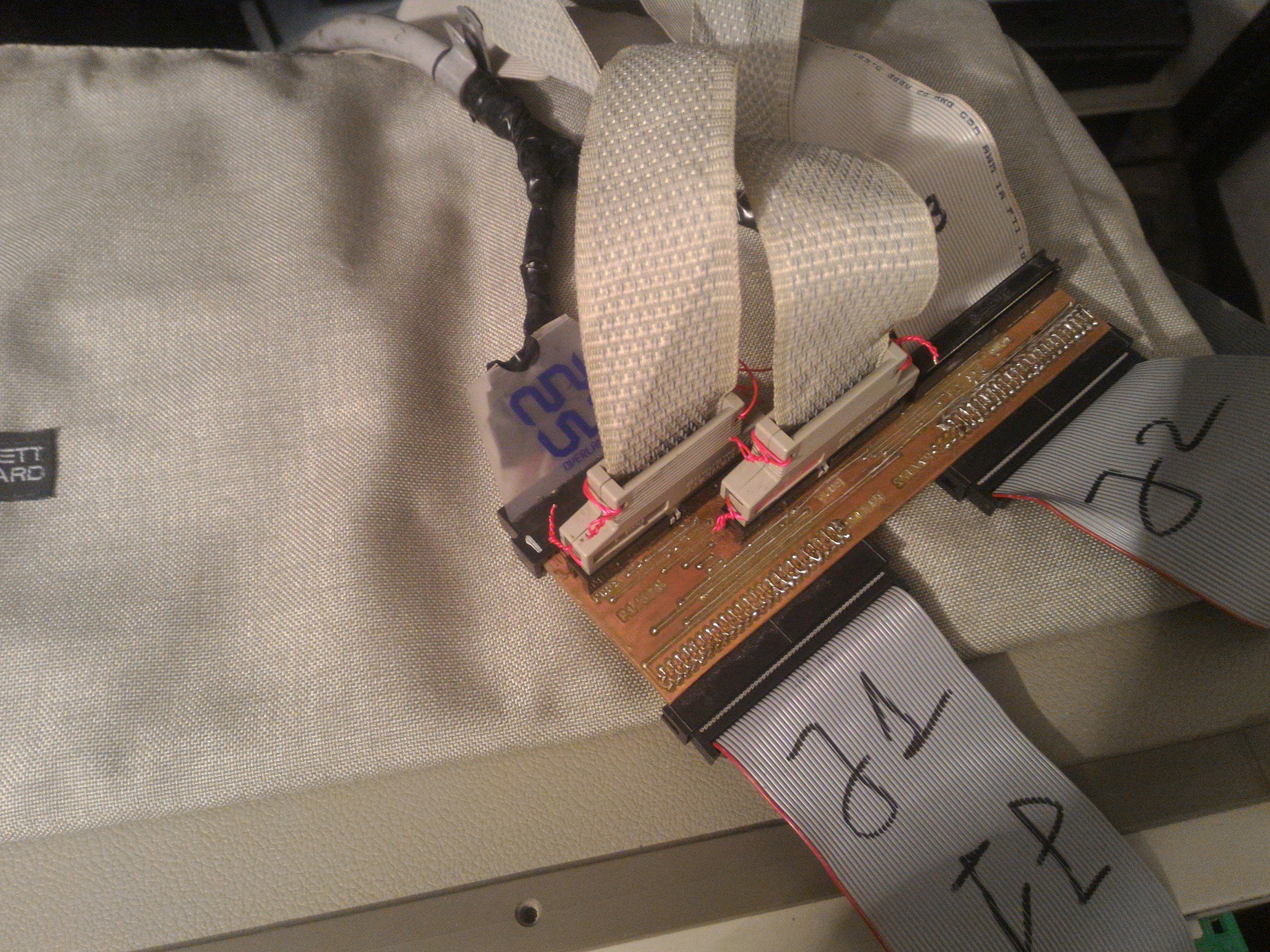
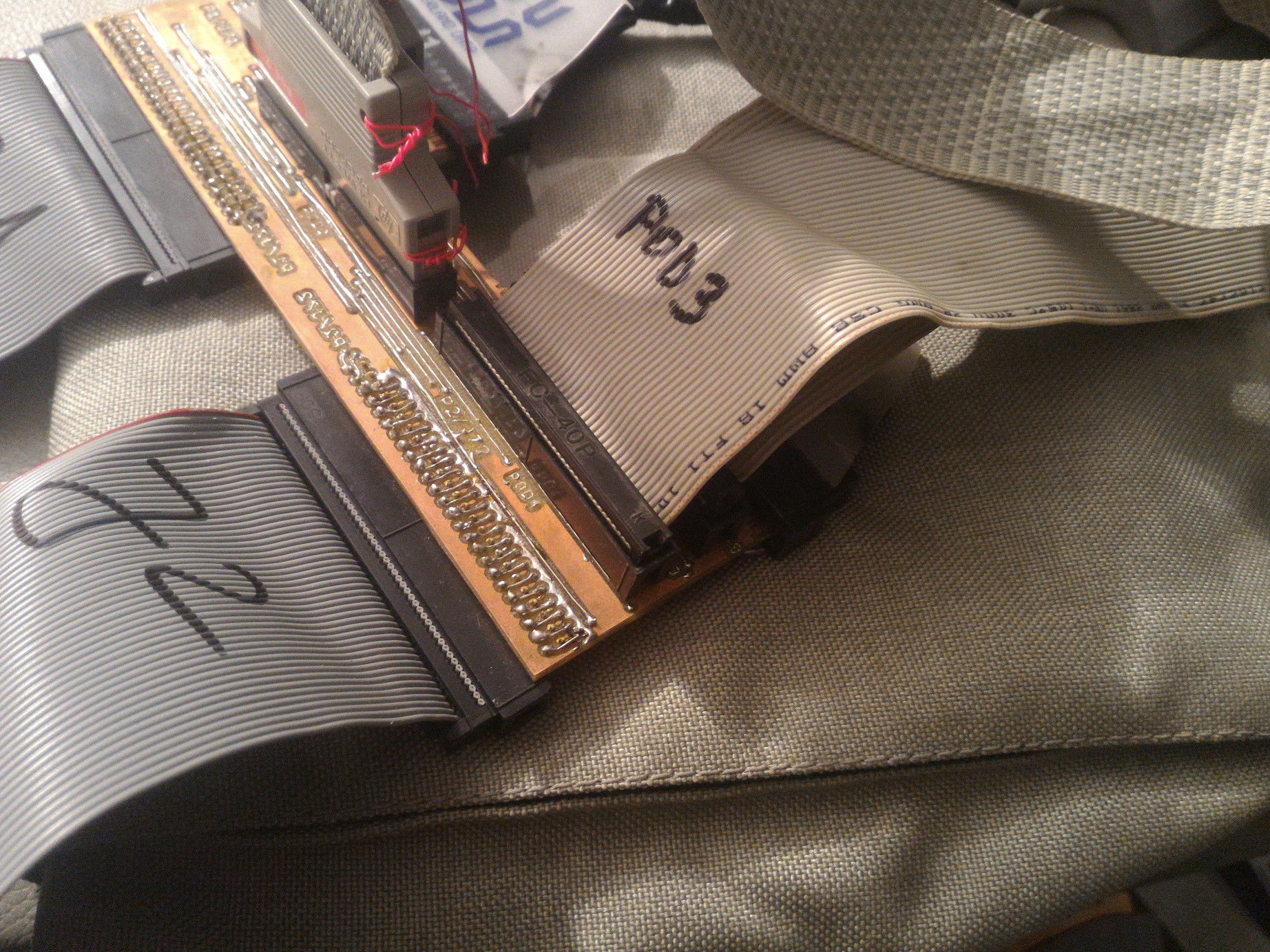
     This is the pertec interface interceptor from the controller (mainframe) side of the Whisperer.  In the back side there are two card-edge-50 connectors, that's the input. The J1 and J2 outputs go to the 'mainframe' connector shown in the 5th picture.

    You can also notice the 4 x IDC40M connectors. With them I can inspect the traffic using the HP1662 analyzer at input, inside the system and there is also another pertec interceptor at the output. This way I can trace any operation failures. 

    Party time!

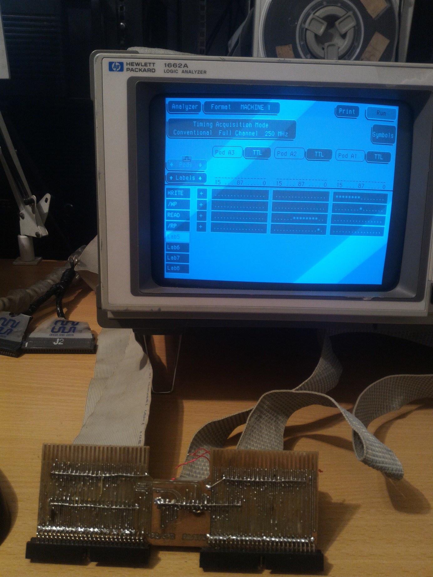
    The analyzer pods are shown here. Whatever line is up, it means logic 1. Down is logic 0. 

    The Pertec interface use inverted logic, meaning a drop of voltage means true.... and from now on it is extremely important what kind of beer I chose in order to see the true data in the inverted flow.

    This old beast has a beautiful manual with a lot of pages showing the complex...

    Read more »

  • It's alive!!

    [skaarj]02/20/2019 at 20:21 2 comments

    My Frankenstein motherboard just completed its first test - serial RS232 data transfer at 9600 baud to the VFD Display. 

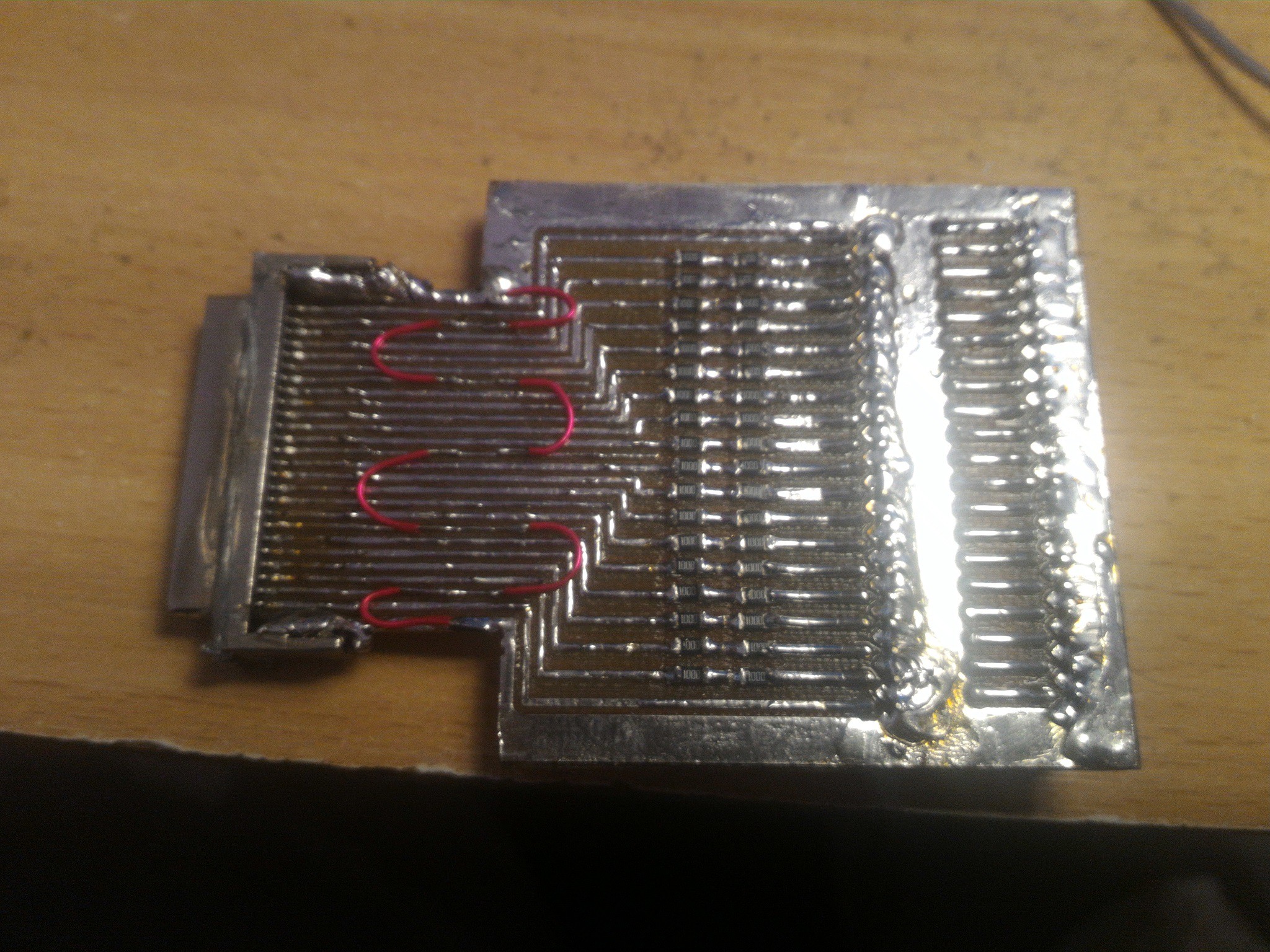
    A friend sold me a HP 1662 logic analyzer with one of the probing cable missing, so I built an adapter.  All those vertical IDC40-M connectors you see on top of the peripheral boards will go to this logic analyzer.

    In the mean time I am preparing the box where all this frankenmonster will stay hidden.

  • The Main Board (II)

    [skaarj]02/17/2019 at 21:27 2 comments

    Work in progress - I have to check and re-check every pad, every hole, every piece of circuit because my CNC is old and its work is far from perfection.

View all 17 project logs

  • 1
    Find an old mainframe

    Stealing it is excluded due to its huge size. Try to negotiate.

  • 2
    Bring it home

    Transport may be a problem but it can be done.

  • 3
    Start hacking

    Remember to gather as many boxes of documentation as you can. Get all the tapes, all the floppies, all the manuals, papers, folders, no matter if they look perfect or they are eaten by rats. 

View all 3 instructions

Enjoy this project?

Share

Discussions

Ken Yap wrote 06/22/2019 at 11:21 point

Wow, congratulations! 👏 Have a beer, good or not.

  Are you sure? yes | no

Sophi Kravitz wrote 03/27/2019 at 00:32 point

...as a result of my witchcraft activity... HAHAHAHA thanks for sharing this hilarious and awesome project :)))

  Are you sure? yes | no

[skaarj] wrote 03/28/2019 at 20:01 point

I like to treat complicated work with fun or else me or the people I work with may get depressed.

  Are you sure? yes | no

Ken Yap wrote 10/22/2018 at 06:36 point

Hahaha I like your sense of humour, e.g. step 1 of instructions, and the beer. I'll certainly be following your progress with interest.

Re the VHS tape nearly 3 decades ago I tried the reverse, using TK50 tape from a MicroVax in a VHS cartridge. It failed because the computer tape was metal particle and the VHS recorder wasn't designed for that. I'll go read your report now.

Regards, Ken

  Are you sure? yes | no

[skaarj] wrote 10/22/2018 at 20:22 point

Hello,  thank you for your appreciation. I will be quick - news for everyone: project is on hold since May this year. Busy building my house + my lab. At the end of this month I move in and I continue working on this. I am stuck at software side and I found some mistakes in my design. Some pins are short-circuited (again lack of good quality beer), some control signals are connected to GND according to "the Western Imperialist documentation" on bitsavers but explained better by the soviet schematics ("acquired" from the same western sources) - some good beer helped me descipher the Russian hieroglyphs. They are connected to GND by the CPU (set to low) only in some particular cases. So I have to re-design the board and either build it an CNC or order from PCB-Electra. CNC is faster but a lot if work with through-hole bypass via copper rivets. Then, again, software hell.

I am not familliar with ancient western mainframe tech due to the political conditions in those times, when only tech from our "liberators" was available.

  Are you sure? yes | no

Starhawk wrote 04/16/2018 at 21:08 point

Well this is about as cool as liquid nitrogen :D

Good luck! +Like, +Follow.

  Are you sure? yes | no

Arnaldo Pirrone wrote 04/13/2018 at 13:16 point

Hi, about 3 years ago, something has been done with PERTEC tapes.

If it could be of any help:

https://museo.freaknet.org/it/recupero-dati-nastri-magnetici-del-computer-polacco-mera-400/

  Are you sure? yes | no

[skaarj] wrote 04/13/2018 at 15:44 point

Thank you. I know about the experiment, I even talk to one of the hackers involved in this project. What they did is set the drive from internal jumpers into service mode to forward the tape until the end. During this time, a data logger was connected to all the 9 signal amplifiers. The resulted data was processed further and they managed to rebuild many tape images successfully. .

They concentrated all their effort on data recovery. Talking to the drive using its interface was not part of their project. This is where I am trying to push the frontier.

  Are you sure? yes | no

Similar Projects

Does this project spark your interest?

Become a member to follow this project and never miss any updates