 Tim Wilkinson
The joint design is built around the tiny gear motor. This is only 6mm in diameter and 18mm long. The goal was to put the motor in the body of the joint, together with the necessary control circuitry, to minimize complexity and external wiring.
The fundamental problem with the design was to turn the rotation around the z-axis into rotation around the x-axis in the smallest space possible. I initially experimented with a number of solution before finally settling on the use of a worm gear which completely encases the motor.
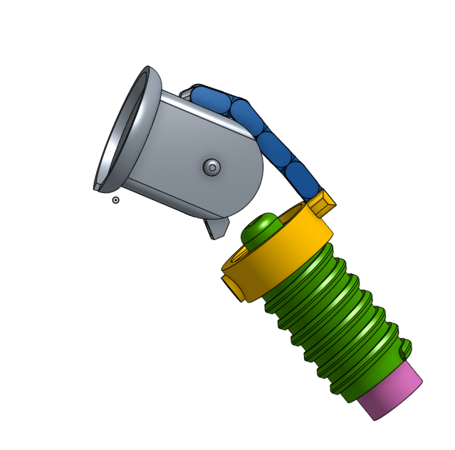
In the picture above, the motor is encased in the green worm gear. The yellow nut is moved up and down as the gear rotates, pulling on the grey pivot (I've omitted the other part of the pivot and the casing so the mechanism can be seen).
The current downside with this design is how the pivot returns to the neutral position. When the nut moves back up, the links are more likely to flex than push the pivot in the correct way. To fix this, a small elastic thread is used to apply a force and pull the pivot back to neutral. While this works, I think of it as a hack and intend to eliminate this requirement if I can.
Discussions
Become a Hackaday.io Member
Create an account to leave a comment. Already have an account? Log In.
This use of an elastic can actually be a feature - measure the axial deflection and you have built a series elastic actuator - you now have force/torque measurement!
Are you sure? yes | no