Kevin Kessler
-
Capacitor and PCB leakage
04/20/2018 at 03:41 • 0 commentsI got my PCBs from China, and I threw one in the toaster over, to build my device. I was ready to connect the display when I found a problem. The connector on the Waveshare ePaper Display is an 8 pin JST XH, the same ones used as balance connectors on Lipo chargers, so I bought some 8 cell balance cables from Aliexpress a few weeks ago for this project. Doh, 8 cells charging cable have 9 pins, and they just aren't going to fit in the 8 pin connector on the ePaper display. While I prefer just buying professionally crimped connectors, I was in a bind, so I order a small kit of JST XH crimp connectors with Amazon prime. When they come in I'll finish the build.
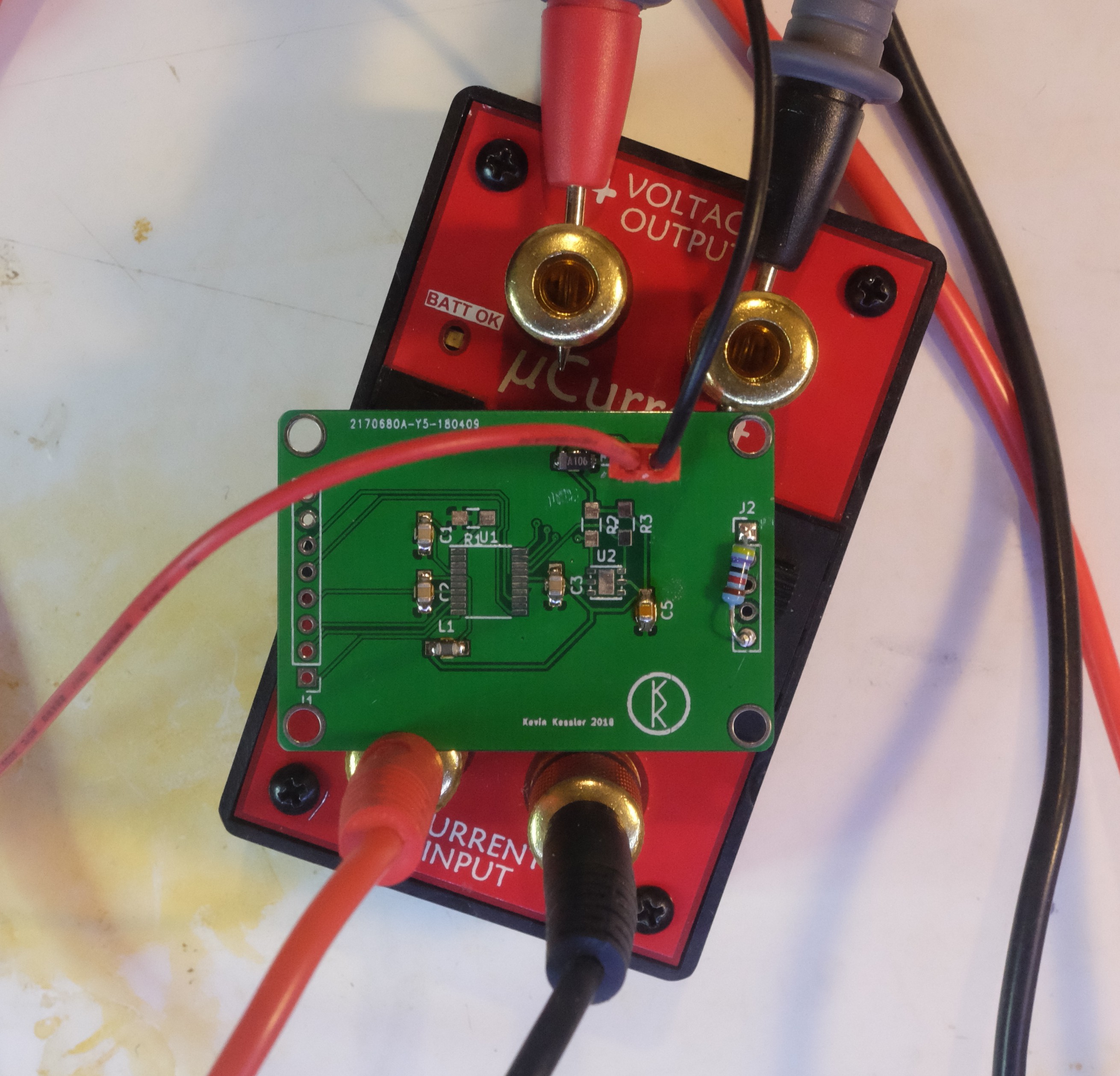
All was not lost, though, because you always get a bunch of extra PCBs when you order them, so I just installed all the capacitors and the bead on a PCB, to measure the leakage current of the capacitors. Reading the Jack Ganssle article on real world low power uC, he states the coupling capacitor leakage can be a real drain on battery life. I decided to measure this:
![]()
The resistor is between Vdd and the NRST pin, and models the internal pull up resistor on the reset pin of the STM32L0, to which a 100nF cap is connected.
The result? The leakage current was immeasurably small (less than a nA), which was somewhat disappointing. The capacitor beside the power connector is a 10uF Tantalum, and I had bought some 10uF MLCC caps to compare the leakage between the two types of caps. I figure there are 3 possible reasons for this. Jack Ganssle had overstated the importance of capacitor leakage, my uCurrent was not measuring low currents well, or I am some sort of savant when it comes to designing low powered PCBs. While I favor the latter answer, I did have an issue with my uCurrent's uA range, where the shunt resistor was about 1.5K instead of the 10 ohms it was supposed to be. I just slapped in a new resistor and fixed it, but I thought I should verify the nA range as well. The shunt in that range measured the 10k Ohm it was supposed to be, but I built 100M resistor out of some 20M I had, put 1 volt across it, and the uCurrent read 9.6mV, which corresponds to 9.6nA, and is close enough to 10nA for this work. To give credit where it is due, my Siglent SDM3055 was also able to measure that current at between 9 and 10nA, but I'm still not real pleased with that meter because it takes so long to start up.
I guess I'm that good at PCB design.
-
Standby Mode
04/16/2018 at 03:13 • 0 commentsThe obvious answer to the idle current is to enable standby mode, which I did next. Standby pretty much shuts the processor down, except for the Real Time Clock, which is used to send the wake-up interrupt. When the processor receive the interrupt, The entire boot sequence starts over again, so there is not much use to the infinite while loop in main, because it goes into standby mode before looping a second time. When put into standby mode, the current in the idle loop dropped to 76 uA.
While a low number, 76uA is still much higher than the 250 nA sort of number I am suppose to get with a STM32L0 in standby mode. Pulling some wires, I found that the standby current of the ePaper Display was 74uA, which is pretty high for a device that keeps the display even if there is no current. In fact, just in sleep mode, that 74uA would drain a coin cell in 4 months by itself.
I tested running the ground through an open drain output, and turning off the ground of the ePD when the device when into idle mode, basically turning off the display. This dropped the current to 2.9 uA. Of that, the SI7091 draws .6 uA, and the rest is from the processor, and leakage elsewhere on the breadboard. Of course I have a PCB for this circuit heading here from China, and it looks like I already have to add a bodge wire.
The code after these modification is tagged StandbyMode and is here.
-
Adjusting the Clocks
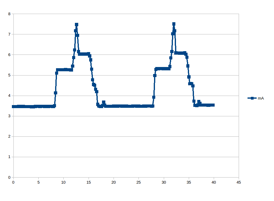
04/13/2018 at 15:10 • 0 commentsThe STM32 series has a complicated clock setup. Configuring the clocks is made much easier by using the STMCubeMX tool, and I initially configured the clocks to use the High Speed Internal 16Mhz clock. The current usage for the device in this configuration looks like:
![]()
This chart shows the higher current usage when the device is reading the sensor and displaying the data, and lower, flat line current usage when the device delays for 10 seconds, before repeating the process. Using some primitive calculus, the area under the active phase shows the device consumes 0.0132 mAh of energy (5.66 mA average current consumption during this period). Using an idealized CR2032 cell with a capacity of 240 mAh, this means that the device could run 18237 display updates before depleting the battery (ignoring any idle time between the updates). The average current usage during the idle time is 3.49 mA, which equates to depleting a coin cell in 68.7 hours, if the device just continuously idled.
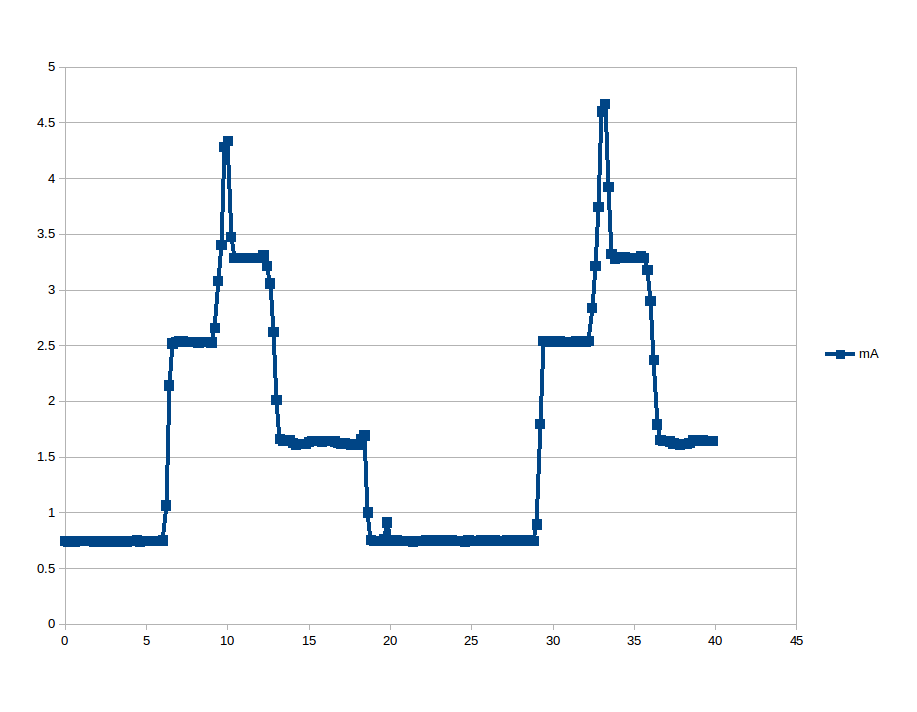
The low powered STM32L series of processors have another internal clock, know as the MSI, Multi-Speed Internal clock. Switching to that clock is just a matter of clicking the MSI in the STMCubeMX clock configuration screen, and selecting the speed. I set the MSI to 2.097Mhz, and got the following current utilization:
![]()
Here the energy consumption during the display phase was 0.00813 mAh (2.36 mA average current during this period), which is a 16.25% decrease in energy usage. This is somewhat surprising, since, because of the lower clock rate, the display phase, with its heavier current usage, is 4 seconds longer than with the faster clock (12.4 seconds vs. 8.4). Using the MSI means that a CR2032 has the energy to do 29520 display updates.
Unsurprisingly, the idle current with the slower clock dropped to 0.745 mA, leading to a vast improvement of battery life of a totally idling system to 322 hours.
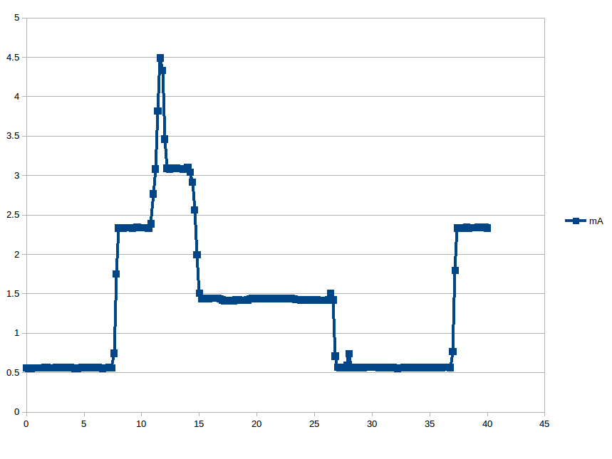
Finally, I set the MSI clock from 2.097Mhz to 1.048Mhz (yes, kind of weird frequencies, but that is what is available):
![]()
At this point, diminishing returns have finally caught up with us. While the average current during the display phase has dropped to 1.92 mA, it takes 19.2 seconds to complete the display update, so the total energy for the display phase at 1.048Mhz is 0.0103 mAh, meaning a coin cell can only do about 23200 updates, more than 6300 less than the faster 2.097Mhz clock.
The average idle current is less, at 0.562 mA, but we have better ways to reduce the idle current.
Note: The ST-Link programmer must be disconnected during these test. When the programmer is connected it the circuit, it draws a lot of extra current.
Coin Cell Powered Temperature/Humidity Display
Using an ePaper Display, investigate getting the lowest possible current usage from an STM32L0.