-
Finally Completed this Project
12/02/2018 at 06:53 • 0 commentsWhile waiting for my new PCBs to come in, I started a new project; building a Delta 3D printer from scratch. That consumed all of my time, and when I was finished with that and returned to my ePaper Temperature and Humidity displays, I realized I made a mistake, so I need to get the PCBs re-manufactured again. After about 6 months of languishing on my bench, I decided to finish this thing up.
![]()
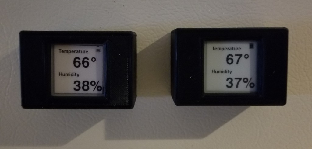
The tri-color display is on the left and the 2 color display is right.
Chugging through the numbers, about 75% of the lifetime on a CR2032 battery is going to be determined by the number of times the screen refreshed, with the rest being the idle current. According the my calculations, the tri-color ePaper disply should make it 103 days on a battery, while the 2 color display version should last 375 days.
I put fresh batteries on both units on Dec 2 2018, 12:00AM. My calculations tell me that the 3 Color display should die on March 15, 2019 and the 2 color display on December 12, 2019. Of course a lot of this will depend on how much energy the battery can really deliver out of its theoretical 225 mAh.
Things I have learned:
- Keep clock rates on the microcontroller low. It makes a big different in idle current.
- The multicolor ePaper display use a great deal more energy than the black and white ones.
- I2C clock stretching, or anything that pulls the lines down for extended periods of time, waste energy. Try to keep the amount of time the pull down resistors conduct to a minimum.
- Open Drain output on a microcontroller have high RDSon (on resistance) and make lousy switches. Use an external FET if you want to do something like switch power to a peripheral.
-
2 Color Display Low Voltage Issue Solved
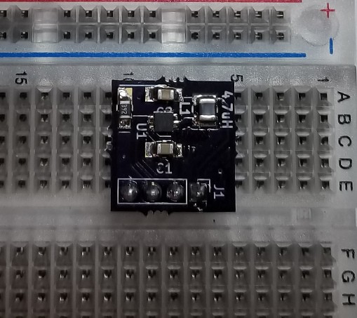
06/01/2018 at 05:22 • 0 commentsI found an excellent 3.3V boost converter, the TPS61261, which I thought would be able to boost the output of the coin cell to a level that would make the 2 Color Display happy. I had some breakout boards made for it, plugged it into my breadboard, and the display worked perfectly, down to 2V. It did take about 25% more energy than running the display without the converter, but that seemed like a reasonable engineering compromise to make since the current usage of the 2 color display is so small compared to the 3 color display. It also allowed me to turn off the power to the display when in sleep mode, and I measured the current of the boost converter when it was off at 35nA, which I was very happy with.
![]()
As I was experimenting with the converter, though, I found out that my problem I was having with the 2 Color display wasn't a voltage problem at all, but it was a problem with using the open drain of the GPIO to switch the ground to power off the display. Basically, the resistance of the internal FET in the STM32 was high enough that a substantial voltage drop appeared between the drain and source of the output FET. The current draw behavior between the 2 and 3 color displays is different enough that the 2 color display just couldn't handle the Vds drop that the 3 color display could. I documented the results in an EEVBlog Forum post where I asked for help understanding this behavior. Using an external discrete switching FET, a IRLML6344, allows the 2 color display to run down to 2 V.
It's kind of too bad I didn't need the TPS61261. I really liked that chip, and I have to find a use for it someday.
I also found in an Arduino library, GxEPD, a different Look Up Table for a full update than the one supplied by the Waveshare libraries. When I tried that, my energy usage for an update dropped from 8.75 mASeconds to 6.3mAS, which would have made up for the boost converter, had I needed it, so now it is just gravy.
So now it is back to China for some new PCBs with a discrete switching transistor. When I get them, I'll do some final current tests, make some predictions as to how long the device will operate on a coin cell, and put in a fresh coin cell and see how close my predictions are.
-
3D Printed Case
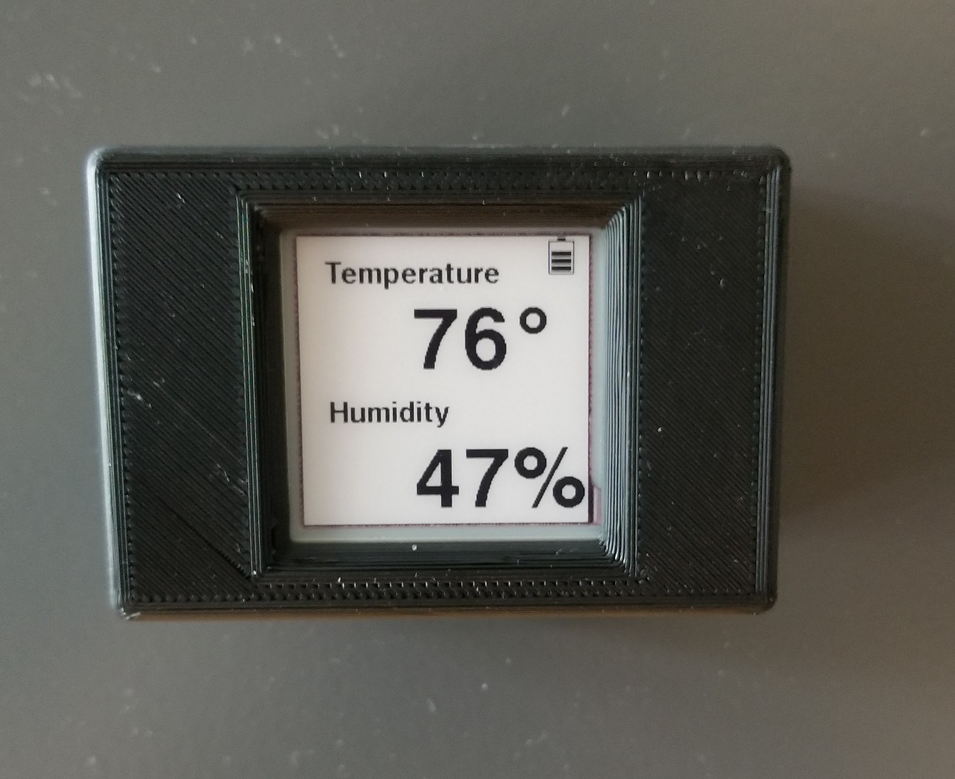
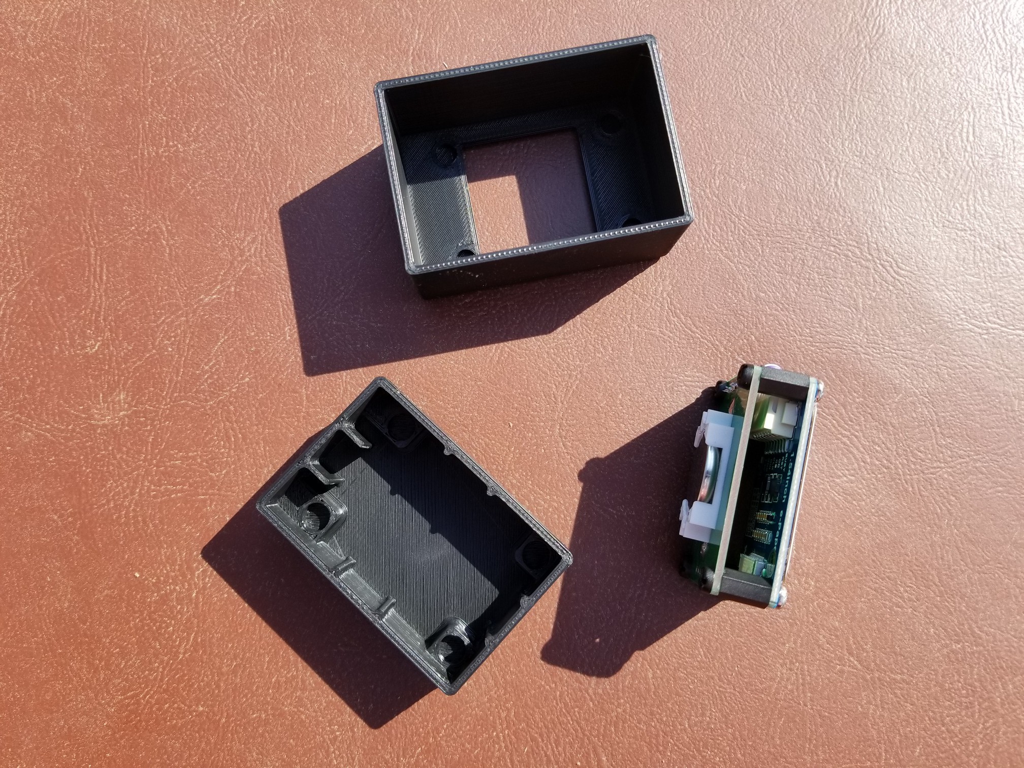
05/25/2018 at 14:32 • 0 commentsWhile I'm waiting for parts and a PCB to do some testing with a boost converted, I designed a simple 3D printed case. It's got a magnet glued in its back so I can stick it on my metal cabinet at work.
![]()
![]()
I designed the case in OnShape, and the model is located here.
-
2 Color E Ink Display
05/10/2018 at 02:54 • 0 commentsI received a Black And While 1.54 inch display module from Waveshare, and compared its current usage to the 3 Color model. The 2 color module is far more battery friendly than the 3 color module, using only about 1/4 the energy to do a screen update. It also has a partial update mode, which uses about 1/13 the energy as an update on the 3 color module, but the screen gets corrupted with the partial update, and wasn't much use for this project.
This makes the 2 color display look ideal for coin cell powering, but... When I started testing it under the lower voltage of a discharging coin cell, I found it stops working at about 2.8 V. Since the datasheet says the display works to 2.4V, I sent an email to Waveshare support. They responded in a timely manner, but their response was:
Hello,
The voltage is for raw panel. You need to consider about the PCB as well.
To down the operating, you made need to change hardware, we don't recommend that.Best regards
Waveshare Service TeamIt looks like there is something about the PCB that doesn't like the low voltages. Since the PCB is just a bunch of capacitors, 3 Shottky diodes, which all tested with a .23 V forward drop, an Inductor, 3 resistors, and an N Channel MOSFET (Si1304bdl), I decided to exchange the MOSFET with a logic level IRLML6344. The IRLML6344 has a better Rdson and Vgsth, but it didn't solve the problem. This is a bit odd, since the 3 color display has essentially the same components on the PCB, and it works down to at least 2.6V. I'm thinking that the COG controller for the 2 color display, IL3820, does not really work down to the 2.4V claimed, or I have a bad display.
-
I2C Temperature/Humidity Sensor
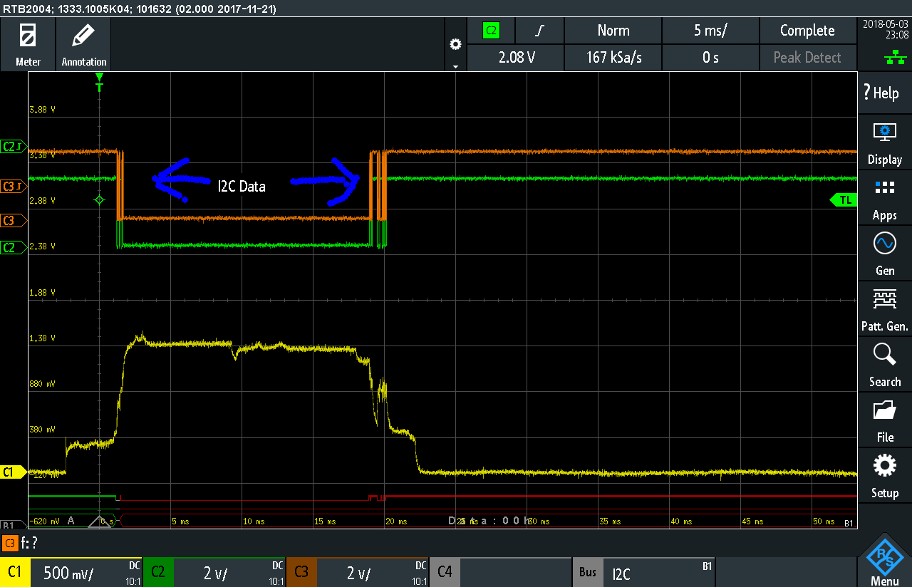
05/03/2018 at 04:25 • 1 commentThe Si7021 is the I2C temperature and humidity sensor used in this device, and it is polled every 20 seconds for data. The current usage for a I2C poll for data looks like:
The orange trace is the I2C Clock line, the green trace is I2C data line, and the yellow trace is the output from the uCurrent. The uCurrent is in 1mV/uA range, so the plateau at 1.38 V indicates 1.38 mA. The bursts of activity on the I2C lines, indicated by the blue arrows (first time I've ever tried the annotation feature of my oscilloscope), are data being transferred between the uController and the Si7021. The burst on the left is the STM32L0 sending an 0xE5 to the device, which means get the humidity reading using what is known as clock stretching to hold the uC while the Si7021 measures the humidity and temperature. About 17 mS later, the sensor releases the I2C bus, and sends the data to the controller.
I2C uses open drain signaling, which means a pull up resistor is connected between the I2C pin and VCC. I2C can be run at several different speeds, 100kHz, 400kHz, and 1Mhz, and the capacitance of the lines, and the amount of current flowing, dictate how fast you can run. Since I'm using fairly high value pull up resistors of 10K to keep the current usage low, I set the speed of the bus at 100kHz.
Looking at the above trace, you can see the 17 mS the sensor needs to measure the temperature and humidity is an excellent time to put the microcontroller asleep. There is a feature in the STM32L0 series of controllers that allows the use of the I2C bus to wake the controller from a sleep mode. While the documentation states this wake feature only work in slave mode, I decided to spend a few hours seeing if I was clever enough to make it work in master mode. I wasn't.
Using DMA, though, it is possible to send the 0xE5 command, put the uC asleep for 15 mS, and then awake, wait a bit longer, and read the data:
During the 15 mS sleep, the current usage dropped from about 1.40 mA to 1 mA, and the overall energy usage dropped 20% (from 6.95E-6mAh to 5.5E-6 mAh).
To improving this further, you must think about how clock stretching works. The slave device, in this case the sensor, pulls the I2C clock line down until it is ready to send its data. This means that the 10K pull up resistor has 3.0 V across it, and that is using 300 uA. To make matters worse, as you can see in the oscilloscope trace, the data line is also being held low by the uC, and that is using another 300 uA. That's 600 uA, more than half a milliamp, being burnt and not really doing anything useful.
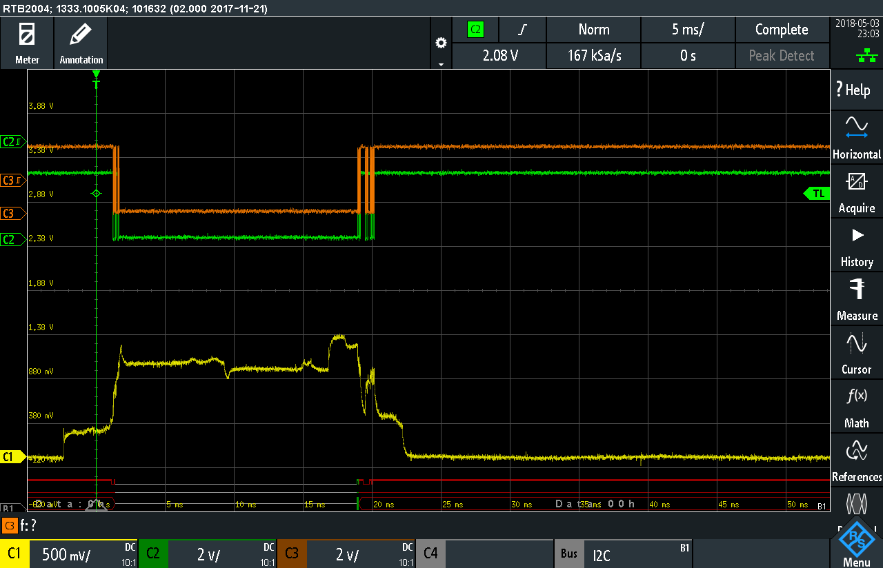
The Si7021 has a polling mode, the 0xF5 command, where it will start to measure the environment, and the uC repeatedly tries to read the data, getting NACKs until the sensor is ready with the data. While this is a more complicated programming task than simply issuing the read command, and the system automatically waits until the sensor is ready, and none of the I2C lines are held low for extended periods of time:
In this case, both the data and clock I2C lines are high during the 20 ms sleep phase. Once the sensor is finished with the humidity and temperature measurement, a measurable current drop is even visible as the sensor goes to sleep, as indicated by more of the fancy annotations. After some testing, I found it is much more energy efficient to over-sleep, and request the data some time after the sensor has completed the measurement, rather than under-sleep, and have to poll until the sensor is ready. I chose a 20 ms sleep. This sleep-then-poll workflow results in about 1/3rd the energy usage compared to the simple clock stretching method (1.91E-6 mAh vs 6.95E-6 mAh).
-
ADC Voltage Measurement
04/29/2018 at 18:25 • 0 commentsThe Analog to Digital Converter and internal 1.25 V Voltage reference is used to measure the battery voltage so it can be displayed as an icon. There are 2 methods that impact current usage during STANDBY related to the internal voltage reference: HAL_PWREx_EnableUltraLowPower and HAL_PWREx_EnableFastWakeup.
Enable Ultra Low Power turns the internal voltage reference off in standby. It takes 3ms for the voltage reference to stabilize and by default, the STANDBY wake routine waits for it. Enable Fast Wake Up does not wait for the internal voltage reference, which in my case, works out because I poll the Si7021 sensor before measuring the voltage, which takes longer than 3ms.
With these setting enabled, the STANDBY current drops down to 1.1 uA. Playing around with disabling the RTC, I found that the Real Time Clock used to wake up the uController, uses about 200nA during standby, and the datasheet claims STANDBY current as low as 250nA, the Si7021 sensor claims 60nA in sleep mode. With the ePaper Display gated off and using pretty much zero current, this means that there is somewhere around 500nA of current usage that might be able to eliminated, although testing firmware that initializes nothing, and immediately goes to STANDBY mode the lowest current usage I could get was about 800nA.
The ADC turned out to be a real rabbit hole to get it to work well.
In normal use, you calculate the voltage of the unknown with:
VDA/4095 X VCOUNT = VUNKNOWN
Where VDA is the ADC Voltage on the VDDA pin, 4095 is the maximum value in 12 bit resolution, VCOUNT is the reading from the ADC, and VUNKNOWN is the measured voltage. In the case of measuring the voltage of the battery supplying the STM32, your unknown is the VDA, and your VUNKNOWN is the 1.25V internal reference so, rearranging the equation above:
VDA = 4095 X 1250 /VCOUNT
Where 1250 is 1.25V in mV, so the answer is returned in mV. This gives reasonable accuracy for this application since it is only displaying 1 of 5 icons to indicate the voltage level, but the STM32s have something to improve accuracy.
At the factory, the STM32L0 are calibrated against a 3.0V source, and that ADC count value is stored in read only memory. You can then read this calibration value, and use the following formula to use the calibrated value to get your supply voltage:
VDA = 3000 * VREF_CAL/VCOUNT
where VREF_CAL is the value stored in memory location 0x1FF80078. Note this location varies by processor, and some processors like the STM32F0s are calibrated to 3.3V, and not 3.0. You have to look both of these up in the datasheet.
I put this formula in my code, turned the crank, and... the calculated values were terrible; far worse than using the uncalibrated equations. What was not clear to me is that you have to run a calibration step, with HAL_ADCEx_Calibration_Start, before you start your ADC, in order to use this calibrated reference. Doing that, and the calculated voltage using the calibration value was spot on.
Running this calibration step is relatively time consuming, and since the ADC (along with every other peripheral) is powered off during STANDBY, it has to be run after waking up every time. It is possible, after running HAL_ADCEx_Calibration_Start, to read the calibration value with HAL_ADCEx_Calibration_GetValue, and store it with HAL_ADCEx_Calibration_SetValue. So, in the firmware, when the uController first boots up, it runs the calibration step and stores the results of the calibration in a RTC Backup Register. When the controller returns from STANDBY, it reads the calibration value from the backup register, and sets it in the ADC. I coded this up, ran it, and ... it didn't work.
Heading down the ADC rabbit hole further, I had to consider how the ADC is configured for low power. First you have to enable Low Frequency Mode, whenever the clock is less than 3.5 MHz, which it is in this case. That one did not cause an issue, but Auto Off did. When Auto Off is enabled, the ADC is powered off automatically when it is not doing a conversion to save power. The issue arises because, in order to set the calibration value with HAL_ADCEx_Calibration_Start, the ADC must be enabled, but not running a conversion, a state that never happens when Auto Off is enabled. Disabling Auto Off allowed me to set the calibration value.
The code for this step in the process is tagged ADC.
-
Improved Current Measurements
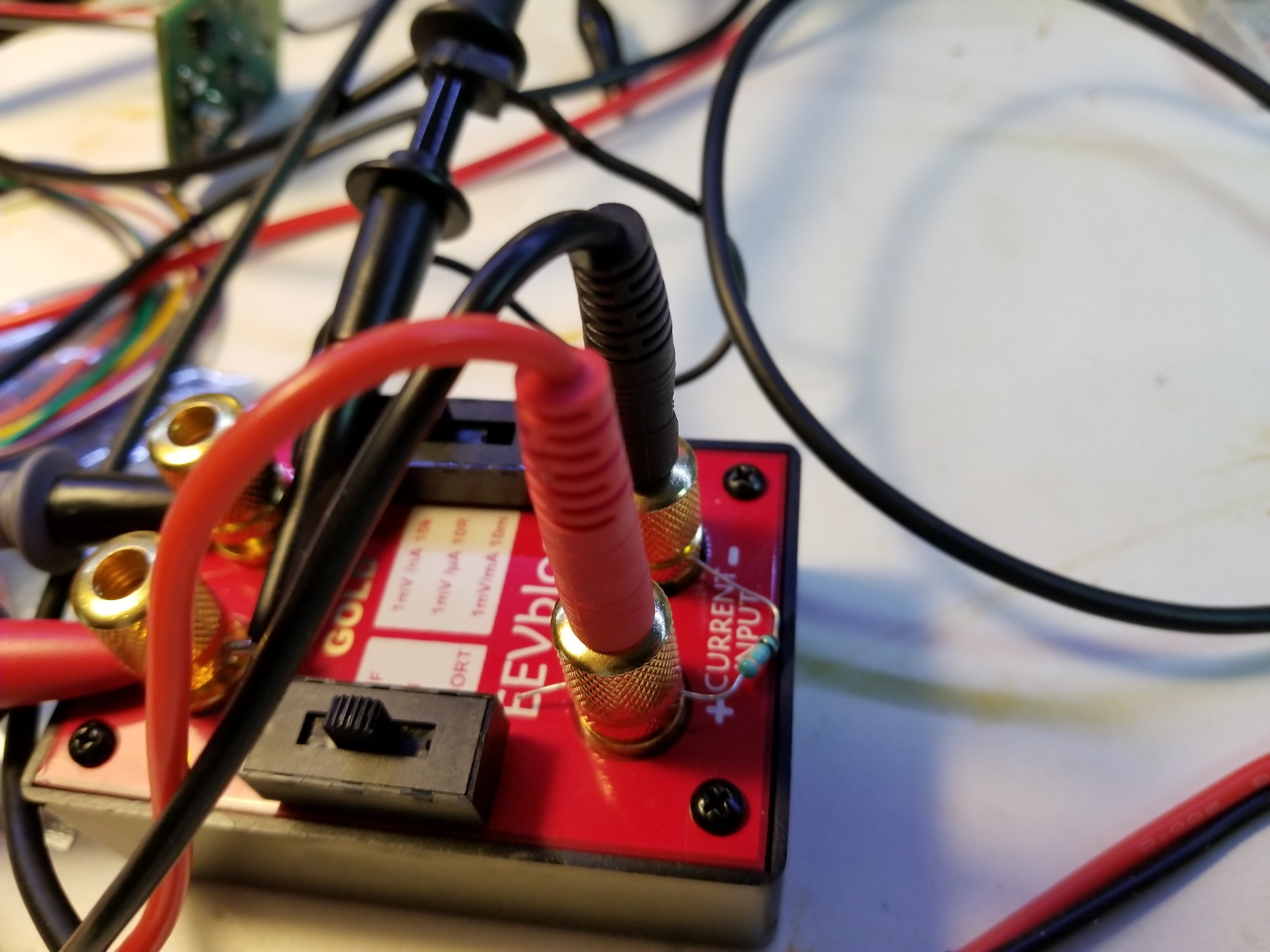
04/27/2018 at 02:38 • 0 commentsOvernight, I realized that I could adjust the uCurrent sensitivity by putting a resistor in parallel with the shunt resistor. In the 1mV/uA range, the uCurrent uses a 10Ohm resistor. Putting a 1.1 Ohm resistor in parallel with that gives me a shunt resistor value and the 1mV/10uA range I was looking for.
![]()
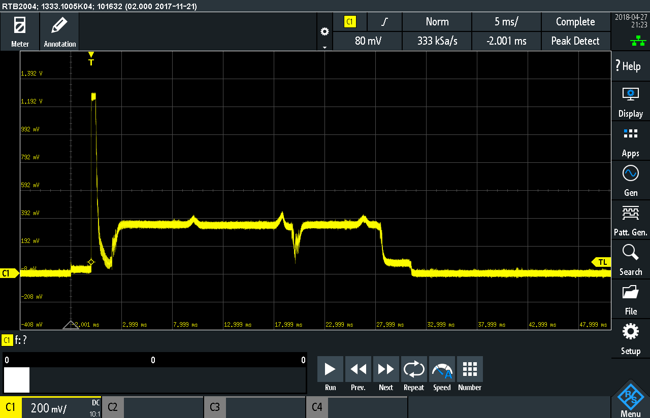
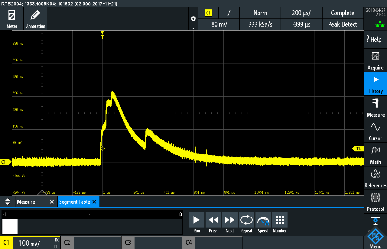
With the 1 Ohm shunt, every 100mV on the oscilloscope represents 1mA, so the trace below shows the uController drawing a bit less than 4mA for most of the 30ms it is active.
At the very start of waking up, the uC draws more than the maximum 12mA that can be measured in this configuration, so I put a .1 Ohm resistor in parallel with the 10K 1mV/nA shunt to give me a .1 Ohm shunt. This makes the range 1 mv/100uA. With this shunt, 100mV on the scope represents 10mA.
This trace shows the current peaks at about 46mA, but note the time scale on the bottom. It is 200us per division instead of 5ms per division in the image above. In about 700us, current drops down to the single digit mA.
Crunching all this data shows I was off with the multimeter measurement by an order of magnitude. Still, the numbers indicate that this process could run almost 8.4 million times on the 240mAh battery. It also shows that taking the temperature and humidity measurements requires only 1/300th the energy compared to displaying those measurements.
This was probably a pointless exercise, since it represents such a small part of the energy usage of the system, it was interesting to see that for a very short time during startup a fairly large 46mA of current flows.
-
Backup Registers
04/26/2018 at 05:19 • 0 commentsThe biggest current hog in the entire system is updating the display, so the best way to limit current usage is to limit the number of times the ePaper display gets updated.
STM32L0 processor have 20 32 bit registers whose contents are saved even in STANDBY mode, when all other memory is lost. Using these backup registers, the new code stores the previous values of the temperature, humidity and voltage, and during the next poll for new data, if the values have not changed, the display is not updated. While the polling occurs every 20 seconds, the display will not update more than once a minute to keep rapidly changing temperature from excessively draining the battery.
Trying the measure the current during the times when the temperature and voltage measurements are taken is very difficult. Using my oscilloscope, I can see the entire process from wake back to sleep takes about 30ms, but the uCurrent's limitations really get in the way here. In the 1mV/uA range, the uCurrent maxes out at about 1.25, which means that the current drawn is greater than 1.25 mA. In the 1mV/mA range, though, the few mAs the device is drawing is only registering a few mV on the scope, which is just down in the noise. What I really needs is a 1mV/10uA or 1mV/100uA ranges, which the uCurrent does not have.
Using my meter, which is only updating at every 200ms, a rough estimate of the energy usage during a temperate poll is about 1/2000th of the energy used to update the display, although this could be off by an order of magnitude or 2. It is also impossible to guess how often the display updates, since an environment with very inconsistent temperatures is going to use more battery than a stable temperature environment. While difficult to quantify, this is probably the biggest energy savings technique I will be able to implement.
The updated code is tagged BackupRegisters.
-
Converting Delays to Sleep
04/25/2018 at 04:30 • 0 commentsThe Waveshare ePaper drivers spend a good bit of time in HAL_Delay. When it initially resets the display, it drives the RESET pin low and waits 200ms, then drives it high, and waits another 200 ms. When it updates the display, it kind of loops around waiting on the BUSY pin for seconds until the display is ready to receive another command. All of this wait time is a perfect opportunity to put the uControler to sleep.
Implementing sleeping during the delays had some effect on the energy usage of the device during the update of the ePaper display. The uController alone draws .632mA when executing HAL_Delay, but only .324mA using sleepDelay, shown below. Overall, the energy usage for one display update dropped from 0.0093 mAH to 0.0086 mAH. This corresponds to an extra 2180 display updates on one CR2032 battery.
I re-implemented the delay in the epdif.c file from a simple HAL_Delay, to one that puts the STM32 into STOP mode, and uses the Real Time Clock to wake the controller after the delay:
void sleepDelay(uint16_t delaytime){

    if(delaytime < 25) {
        HAL_Delay(delaytime);
        return;
    }
    else {
        if(HAL_RTCEx_DeactivateWakeUpTimer(&hrtc) != HAL_OK) {
                    HAL_Delay(delaytime);
                    return;
                }
        __HAL_PWR_CLEAR_FLAG(PWR_FLAG_WU);
        uint32_t counter = (uint32_t)(delaytime * 1000) /432;
        if(HAL_RTCEx_SetWakeUpTimer_IT(&hrtc, (uint16_t)counter, RTC_WAKEUPCLOCK_RTCCLK_DIV16)!=HAL_OK) {
                    HAL_Delay(delaytime);
                    return;
                }

        HAL_SuspendTick();
        HAL_PWR_EnterSTOPMode(PWR_MAINREGULATOR_ON, PWR_STOPENTRY_WFI);
        HAL_ResumeTick();

    }

}
This code just does a regular HAL_Delay is the delay is for less than 25ms and goes to sleep for longer delays. The normal pattern for RTC Wakeup power savings modes is to deactivate any RTC timer currently running, clear the Wake Up flag, set a new timer, and enter the selected low power mode. Since the uC will wake up on any interrupt, the SYSTick clock, which generates an interrupt every 1ms, has to be disabled before entering STOP mode with HAL_SuspendTick(), and re-enabled once it leaves STOP mode. To calculate the delay, the 37kHz clock divided by 16 has a 432us period. To avoid floating point arithmetic, I convert the delay time to microseconds, to figure out how many 432us counts I need to wait to get the delay.
A very time consuming part of the display update procedure is waiting for the BUSY line on the ePaper display to go high indicating it is ready to do something else. It is implemented in the Waveshare library like:
void EPD_WaitUntilIdle(EPD* epd) {
  while(EPD_DigitalRead(epd, epd->busy_pin) == 0) {      //0: busy, 1: idle
    EPD_DelayMs(epd, 100);
  }
}
While the EPD_DelayMs call will now go the sleepDelay code, this can be further improved by converting the BUSY line to an interrupt, and putting the STM32 to sleep as it wait for the BUSY line to go high and generate an interrupt. This is implement in the sleepWait function in epdcontroller.c, and is basically a simpler sleep procedure compare to the sleepDelay above, because the RTC is not set. The code can be found in the GitHub repo under the tag STOPMode.
I spent at least a day trying to track down an issue where the device would hang once it returned from STANDBY mode and start to do another ePaper display update. It turned out that when it entered STOP mode in the sleepDelay function, it never returned, and that seemed to be related to the Wakeup Timer not functioning properly (the BUSY interrupt wake up worked fine). After banging my head against a wall for hours, I found the problem was in the STM32Cube generated code. The offending code was this:
static void MX_RTC_Init(void)
{

  RTC_TimeTypeDef sTime;
  RTC_DateTypeDef sDate;

    /**Initialize RTC Only
    */
  hrtc.Instance = RTC;
if(HAL_RTCEx_BKUPRead(&hrtc, RTC_BKP_DR0) != 0x32F2){
  hrtc.Init.HourFormat = RTC_HOURFORMAT_24;
  hrtc.Init.AsynchPrediv = 124;

/* Cut out a lot of code here for brevity */

  }

    HAL_RTCEx_BKUPWrite(&hrtc,RTC_BKP_DR0,0x32F2);
  }

}
The initialization routine for the Real Time Clock would first check for the magic number 0x32F2 in the first backup register (DR0). If it wasn't there, there it would initialize the RTC and write that 0x32F2 number to the register. If it was, it would skip the whole initialization routine. Since the backup registers keep their values even in STANDBY mode, when the STM32 returned from STANDBY, the DR0 register retained its value, and it skipped the RTC initialization. Why the code is generated like this, I do not know, but the only fix I had was to cut and paste this initialization routine to a function called MX_RTC_Init_fixed, and call it in the user code of main.c. See the STOPMode tag in the repo for the complete code. This bug was introduced in STM32CubeMX version 4.25, because code generated with version 4.23 does not have this rouge if statement in it.
Update 5/2/2018: I put a message on the ST Community explained the problem the RTC Initialization bug. Apparently ST Engineers were able to reproduce the problem, because I got a message that it will be fixed in the next release.
-
PCB and New Baseline
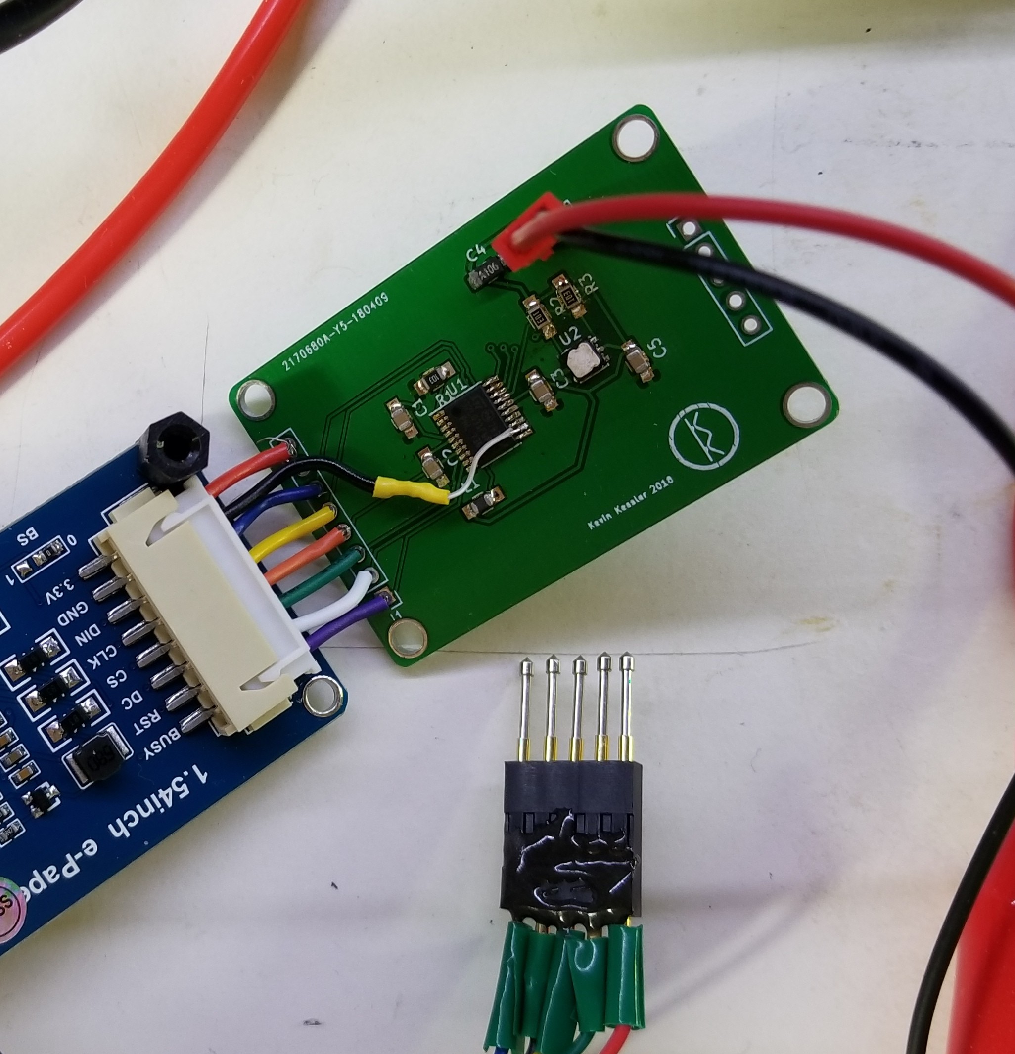
04/22/2018 at 23:01 • 0 commentsI've assembled my PCB complete with bodge wire for the switched GND:
![]()
I re-baselined the current usage, and found that rerouting the GND to switch off the device during standby has a price. During the update display phase, current usage is about 16% higher. I can't really figure out why, but there is no change if I set the GPIO switching the ground from Open Drain to Push Pull. Even with the higher current draw during the update phase of the device, the much lower standby current makes this an acceptable trade-off.
There is no difference between the current use from the breadboard to the PCB, which was a bit disappointing; I was hoping for some leakage or something from the capacitance in the bread board connections.
When you run the STM32l0 below 4Mhz, you can reduce the voltage on the core, from the default of 1.8 V to 1.2 V. This is done in the STM32CubeMX tool, under Configuration -> RCC. Voltage Regulator Voltage Scale 3 is the lowest value. That did not make a big difference in current consumption, though, with less than a 5% improvement in current at the lowest core voltage. It made no difference to the 2.25 uA standby current the device, which is not surprising since the core is shutdown in standby mode.
Coin Cell Powered Temperature/Humidity Display
Using an ePaper Display, investigate getting the lowest possible current usage from an STM32L0.
 Kevin Kessler