Is there anything to be careful about, when dealing with Ge transistors ?
According to a retired engineer, soldering is tricky. I know Ge is very temperature-sensitive but he advised to not cut the leads. I'm still not sure about the exact meaning but Ge transistors can easily get destroyed during soldering. The soldering iron should be set to the lowest possible temperature, and I will find a way to cool the part down before and immediately after the joint is made...
Who else can share their precious advices ?
Now I get it why transistors were socketed back in the days...
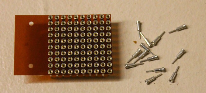
And this might be a solution. High frequency signals require short leads and the transistors should barely sit above the PCB plane to keep lengths and traces as short as possible. I'll have to find thousands of individual female sockets that I solder in the PCB holes. I have a "small" stock, maybe a thousand of them, but that is far from enough for a whole system...

(picture found on eBay)
I use these a lot to make prototypes, they are very handy. Unfortunately, all I can find (yet) is small sockets assembled in one (or two) row with 2.54mm spacing. Any hint for where to find individual pins ?
Furthermore, I would cut the smaller end because the larger socket part would go through the PCB. That's a lot to cut...
Update:
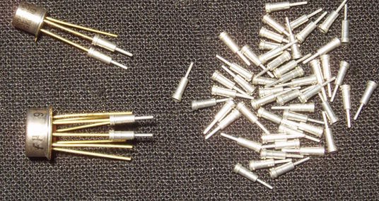
I have about 4K receptacles of this kind:
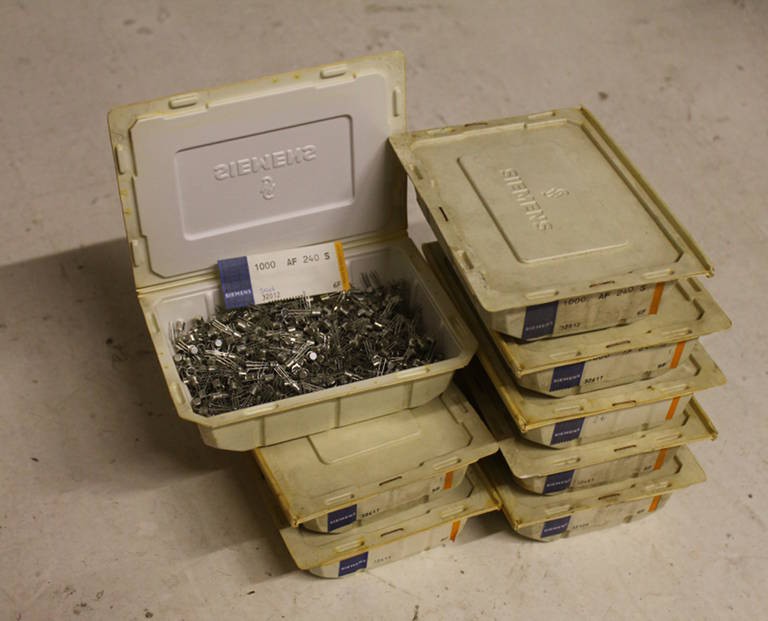
First problem : I only have 4K. The AF240 has 4 pins so that's only enough for 1K transistors (barely enough for the register set alone). I got at least 8K AF240 (see below to see how it looks like) so I'd need a crazy 32K receptacles!
Second problem : To get enough receptacles, I'd have to spend about $200 (that's chinese dollars, you know, you get what you pay for...)
Third problem : Reliability. The transistor doesn't move much but... multiplied by 8K, it's a recipe for catastrophe ! I should rather make small modules with a dozen of transistors and test them well (eventually replace a failed part).
Using receptacles, a vibration, a mishandling or any physical influence could perturbate the circuit, making it hard to use. I'd rather damage a few transistors before use, than spend all my time guessing with can got slightly upset...
Concerning soldering : I did some research of the "mesa" technology and it does not seem to be particularly fragile (compared to others) so I'll make a bet by carefully soldering.
 Yann Guidon / YGDES

Discussions
Become a Hackaday.io Member
Create an account to leave a comment. Already have an account? Log In.
Best idea is to forget sockets and tweezers at all. Because of cost, reliability, and complexity. Besides, locking forceps might crack the glass insulators, and oxygen begin slowly destroy junctions.
Leads should be left 8-10 mm length, use iron of 25 W, solder briefly for 1 second, and allow to cool 5 seconds between touching each lead. That will ensure dices never get hotter than maybe 100C during solder.
Testing (measuring) each transistor carefully before putting on board saves plenty time on latter troubleshooting :)
Danger of overheat is the case of very old and "barely alive" germaniums, the dream of archeologist. Then long leads and/or copper tweezers can help, but with great care to insulators.
Are you sure? yes | no
Damned,
just like with the RES15 I should also make a tester for the germaniums... My TODO list has already exploded however :-/
Are you sure? yes | no
Those look like Mill-Max receptacles.
https://www.mill-max.com/products/rec/0405
Are you sure? yes | no
yes. Given 8K transistors (evaluated), that's 32K receptacles... That would be a crazy bulk order...
Are you sure? yes | no
Yep- and they're probably not as cheap as you'd like. Mouser pricing only gets down to 0.56 at 1k for the 0405-0-15-80-34-80-04-0
Are you sure? yes | no
I remember someone saying that he used cold spray to cool his transistor while soldering it. Rémy from Sonelec-Musique uses single row machined ic socket as transistor sockets.
Are you sure? yes | no
In the case of the AF240 (and its siblings), there are 4 pins so I would use dual-row sockets such as
It seems to be more practical than individual pins (they would stay together) and the strip can be cut in different lengths (even 2)
Are you sure? yes | no
While we're here, can somebody explain the purpose of the 4th pin ?
It's connected to the metal can, should I just ground it ? Leave it unconnected ? Any risk of stray capacitance ?
Are you sure? yes | no
Get yourself a pair of locking forceps. You can clamp on the leads between the solder joint and the "can" and use that as a heatsink.
Are you sure? yes | no
I'm not sure it's both enough and practical... I'll try and see.
Are you sure? yes | no
I have soldered a few germanium with an 40W iron (without temperature control) nor knowing the heat damage issue back when I started out. Never had an issue.
Are you sure? yes | no
Considering the price of the transistors I'll use, the quantity I'm about to receive and the modularity of the system (small PCBs with maybe a dozen of Ge's)... I'll probably just solder and check the module's health.
"AF 240 is a germanium PNP mesa transistor" though I'm not sure what kind of process this is (it's not epitaxial yet ?)
Are you sure? yes | no
and the AF240 have 4 pins so it's going to be... tricky to use :-/
Are you sure? yes | no
I remember reading about the "thermal clamp" method in a 60s electronics textbook *). If I remember right, the tool in the illustration had a small rounded bar of copper perpendicular the leads. Not sure how they avoided bending the leads too much. From my "electronics scavenging" days I remember the UHF radio tuners used to have germanium transistors, and those sometimes were hand soldered, too The leads were rather short (to reduce inductance) .
*) No, I'm not that old. The electronics section in the public library just had rather old books.
Are you sure? yes | no
I used to learn electronics as a kid by looking at old books in the public library too :-)
I'll have to see the practicality of thermal clamps...
Are you sure? yes | no