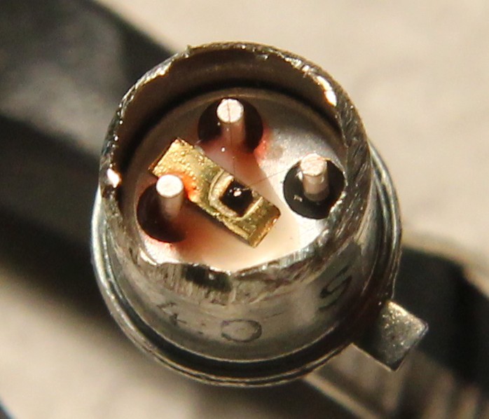
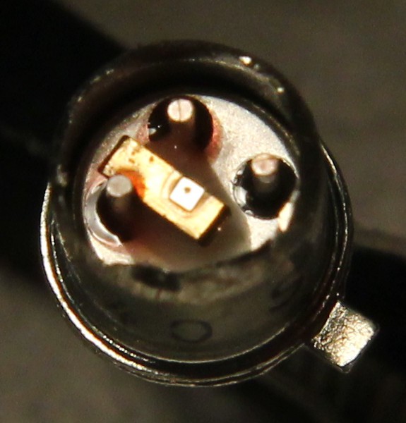
The question of soldering the pins raises the issue of thermal damage, so I looked at the fabrication of the "mesa" type of transistor. I have found quite a lot of informations (thank you Google) but nothing beat "looking by oneself". So I opened on transistor and struggled to make a suitable picture, without dedicated tools...
The wires are really thin ! And they meet at almost the same place, it's hard to distinguish even with optical help...
There are 2 wires, connected to 2 pins. I believe that other than mechanical stress, it's fine during soldering. The wires are straight and can break but the heat might not travel enough through it.
The other two pins are a different story. The "can" pin (who can tell me where to solder it ???) can take the heat but shoudn't get too hot, for many reasons.
The fragile part is the collector (?) : it's the slice of germanium that is directly bound to a pin, and that might propagate the heat to the whole semiconductor. This is the pin to protect with a thermal clamp while soldering...
I broke a few parts but this analysis should help me avoid damage during assembly.
And i still don't know what should be connected to the "package" pin...
 Yann Guidon / YGDES

Discussions
Become a Hackaday.io Member
Create an account to leave a comment. Already have an account? Log In.
If the case is electrically isolated from the device, why not just connect it to your reference potential (ground)? That way, it isolates the terminals from each other and the rest of the universe.
I wish more devices came with isolated cases and/or heatsink tabs - it makes it easier to arrange for thermal dissipation. 78xx are nice with the tab at ground, but 79xx are not. I usually screw that one up :-)
Are you sure? yes | no
Connecting to ground is the most "normal" thing to do, I suppose.
However I am concerned about significant capacitance, low-pass to ground etc.
This is not a concern with the "plastic dot" parts such as the AF279/AF280 or the BFR96 (that silicon beast is sometimes rated up to 6GHz). Without a metallic can, there is only the continuous ground plane that acts as a capacitor...
Are you sure? yes | no
I would guess that the only terminal with more than femto-farad capacitance to the case is the one connected directly to the die. The capacitance for the other two is probably swamped by device capacitance on those connections. So, you could connect the case to the "die" lead, if that made sense.
If there's any significant difference about where you connect it, you'll probably notice soon enough - there is probably no substitute for some bench time with those things :-)
Those are some very fine wires.
Are you sure? yes | no
you have a point... But then if the collector is tied to the case, this increases capacitance even more since the case will be somehow coupled with the environment... damnit...
Yes I'll have to experiment :-P
And yes, fine, crazy fine. Little heat can go through :-D
Are you sure? yes | no