 RigTig
-
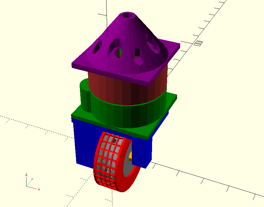
Paper pulp extruder
10/06/2017 at 06:36 • 0 commentsThis is a paper-making machine, reduced to create a 10mm strip of paper pulp, rolls around and around and around to build up a three-dimension object. This is the extruder part.
Thought I'd lost these files, but found them on a USB, so I've put them up on https://www.myminifactory.com/object/46335. Still needs work, but if anyone wants to beat me to it, just go for it.
![]()
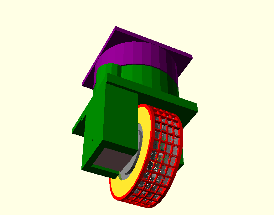
Reworked a bit to suit laser sintering printer: see https://www.myminifactory.com/object/47744
![]()
-
Silicone extruder
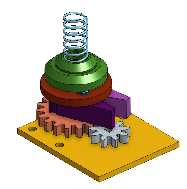
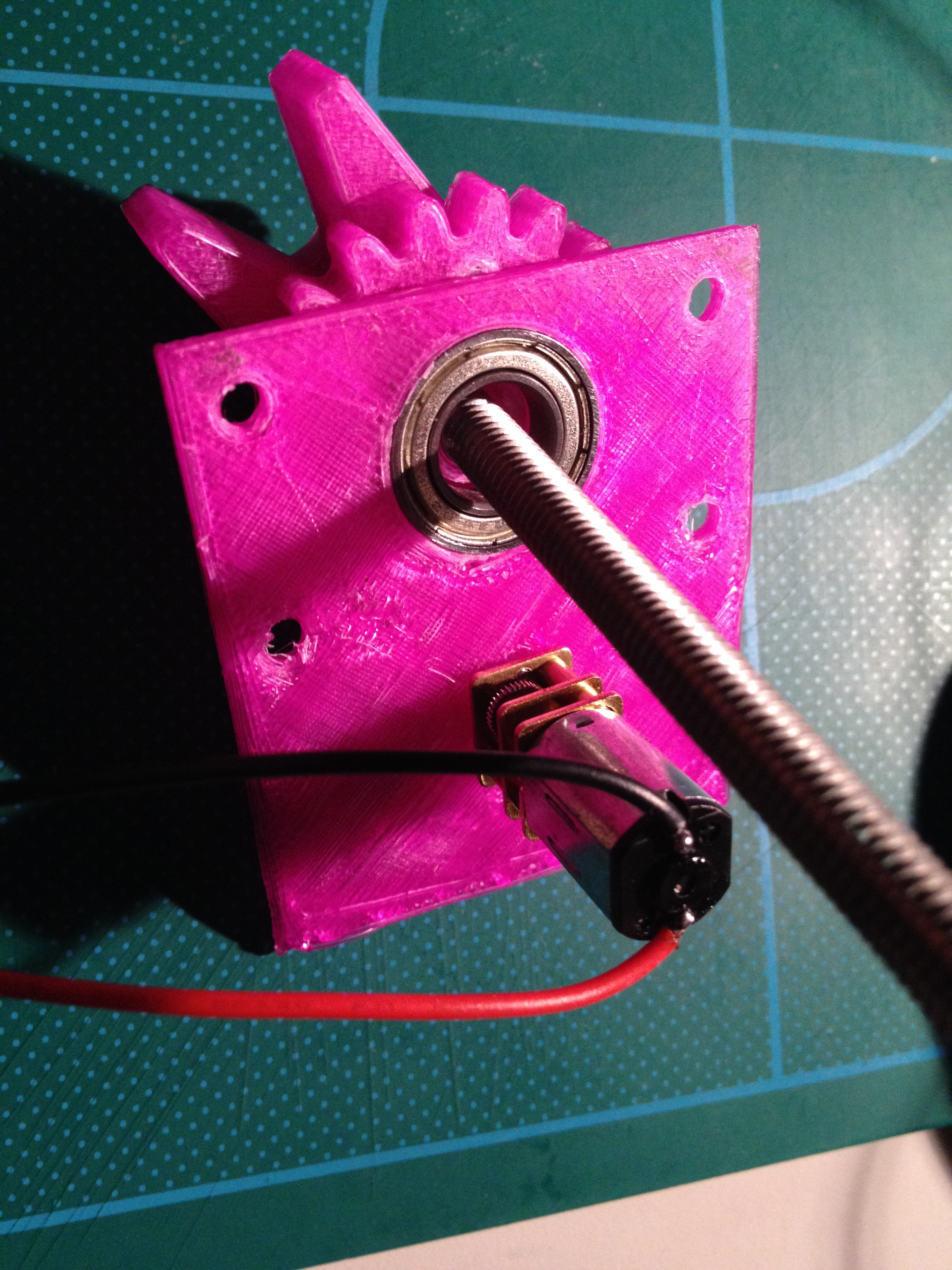
08/16/2017 at 05:44 • 0 commentsA silicone gun is too hard to control using a computer, so I removed the handle and put on an extruder drive. I used a tiny 100RPM 12V DC motor and it seems to have enough torque! More testing to come.
![]()
And the 3D printed version looks like:
![]()
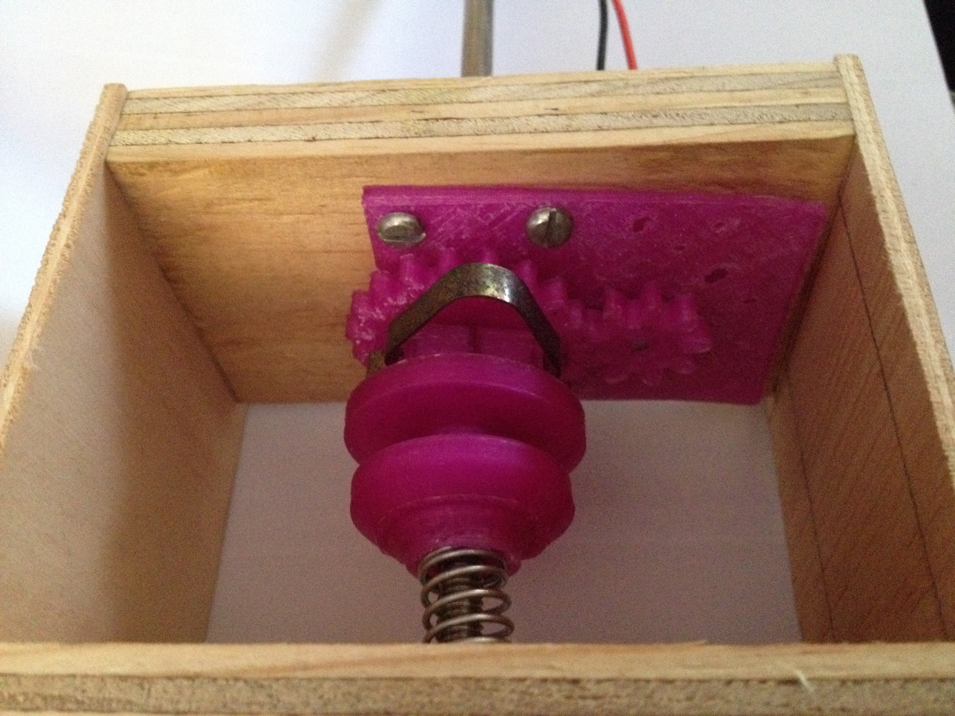
And the motor (yes, it is a 6mm threaded rod):
![]()
For more details, have a look at https://cad.onshape.com/documents/bdf821161c0d3c01945c5e17/w/145cfc7caf50a052aa41e42f/e/ac6f177acba94f862104b01a
-
An effector: a silicone gun
07/09/2017 at 07:09 • 0 commentsThe first effector was a 60ml syringe. This is just a bigger version really. I've got a project that needs to print about a meter square, but only 10 to 20 cm thick, and in something a bit softer than ABS and PLA. Lets try silicone. And what does a builder use to apply silicone? A: a silicone gun. So let's try it.
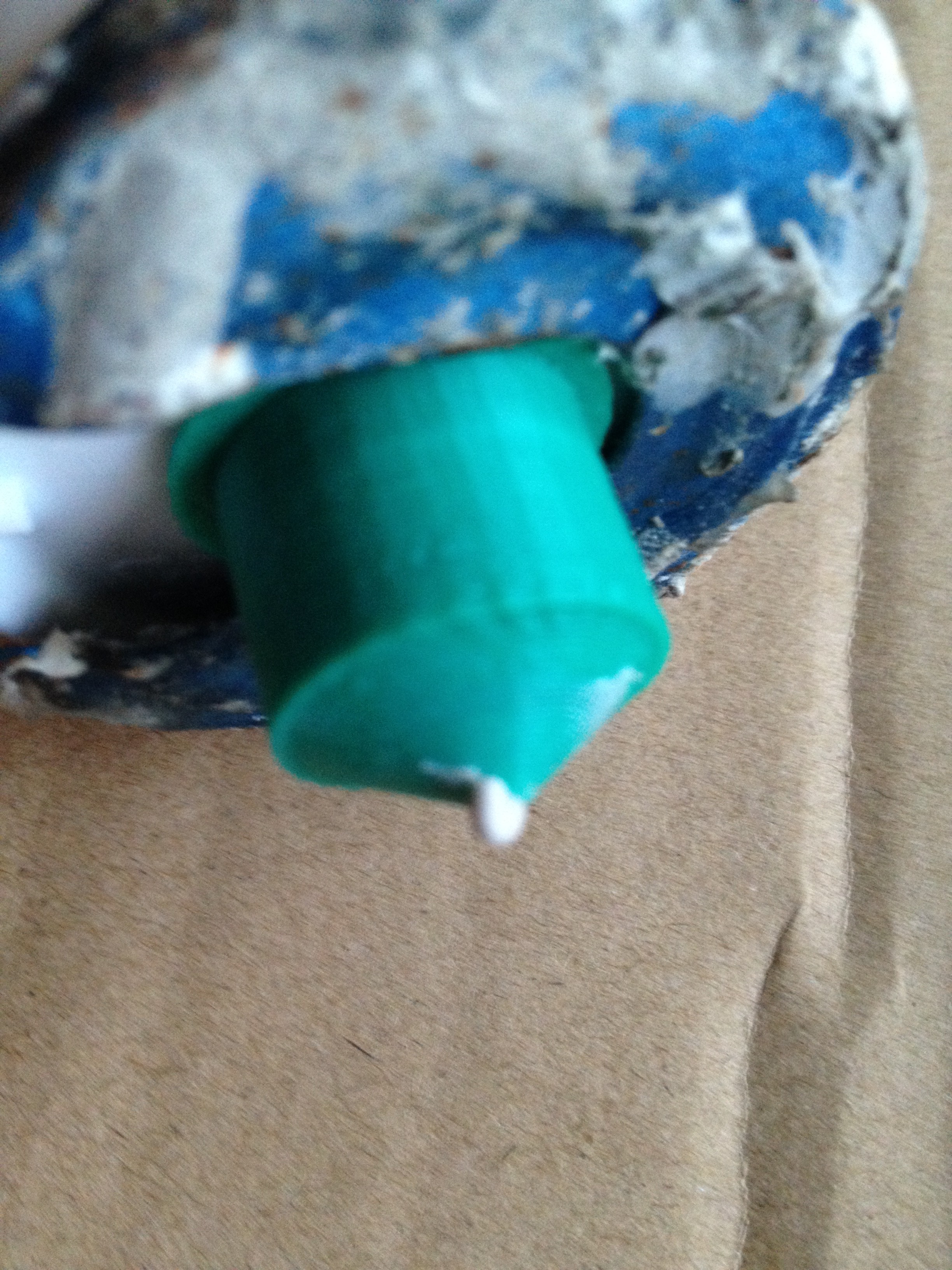
Needed a nozzle about 1.5mm diameter, so I designed and printed one.
use <~/installs/scad/simplethreads.scad>; nozzle(); module nozzle() { difference() { union() { cylinder(d=23, h=1); cylinder(d=19, h=15); translate([0,0,15]) cylinder(r1=9, r2=1, h=5); } thread(3.0, 16.5, 12, 4.0, 0.3, true); translate([0,0,13]) cylinder(r1=8, r2=0.75, h=6); // hole cylinder(d=1.5, h=30); } }![]()
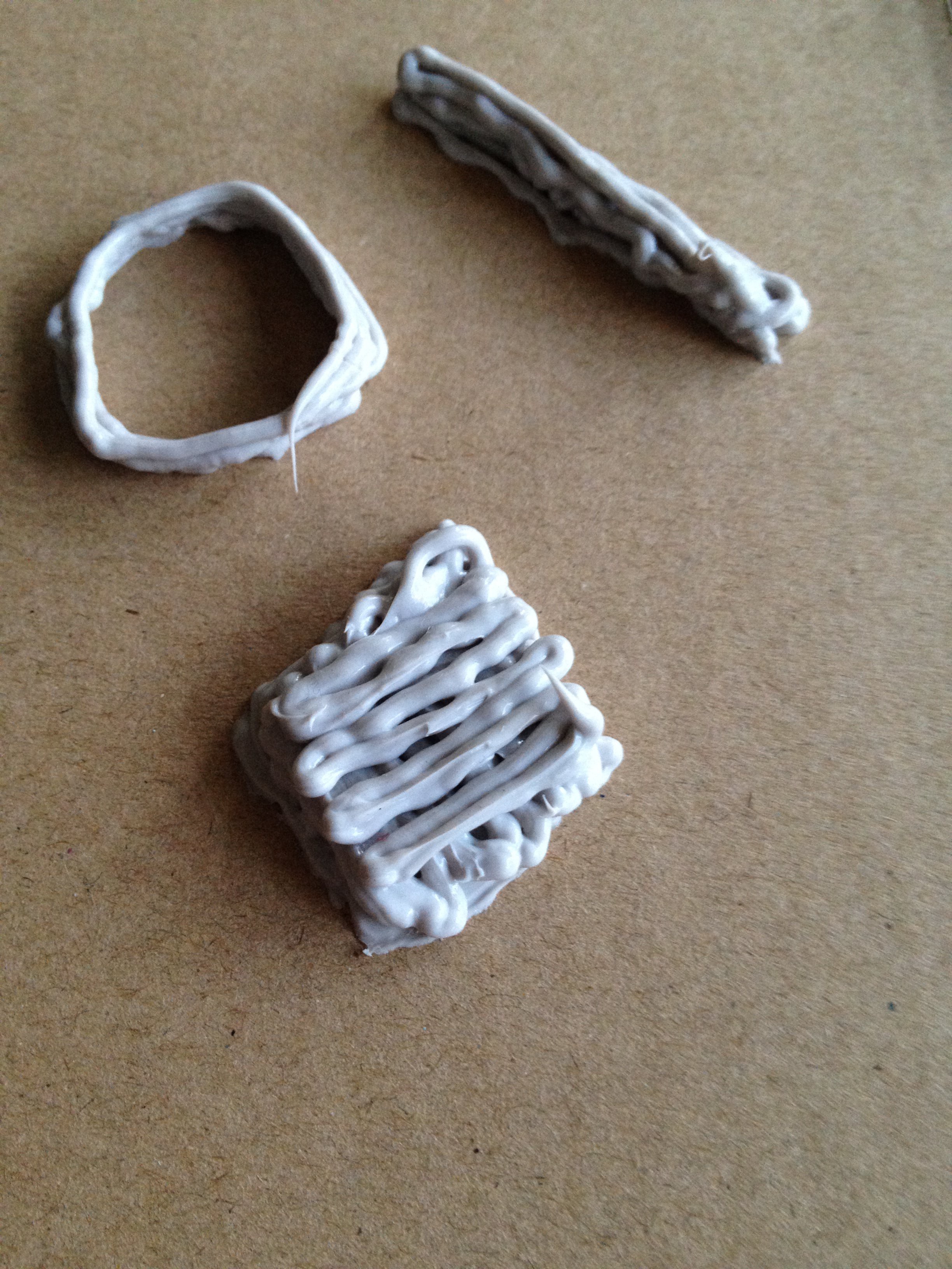
How stable is a series of layers of silicone? Well, try it by hand and observe the results.
Soft and squishy! And it looks like it'll hold up enough.
![]()
OK, now to design a controllable squeezer for the cartridge. Mmm...need something with a bit more torque than the tiny steppers used earlier. Maybe I can try using an R/C motor and an ESC control.
tbc...
-
Calibration with multilateration using W1209
04/03/2017 at 00:52 • 4 commentsTo calibrate RB3DP, the idea is to set up a calibration object, manually move effector to 5 points on that object (at each point, record relative lengths to each winch) and calibration is just some arithmetic to derive the x, y, and z coordinates of each motor winch. So, we need a controller, which (of course) must be very inexpensive, so the choice is W1209 board (see https://hackaday.io/project/16097-eforth-for-cheap-stm8s-value-line-gadgets ) plus an ESP8266 for WiFi.
The key for getting this to work is multilateration and the maths is on wikipedia (see https://en.wikipedia.org/wiki/Multilateration#Solution_with_limited_computational_resources). Many thanks to @Florian Festi for identifying multilateration as being a key solution to our calibration problem.
The problem was that we did not know the lengths of the strings even if we knew the location of each of the motors (by physical measurement and typing them in). We can measure changes in length however, and that is what multilateration uses; differences in lengths. If you use 5 known points then you can calculate the cartesian coordinates of 3 motor winches. The origin is the one on the calibration object, so there is no transformation needed for different reference frames; everything is referenced to the object space. Another advantage is that there is no restriction on having the motor winches on a plane parallel to the baseplate. In fact, even the orientation of the axes is independent of the physical orientation of the motor winches.
So, we need a calibration piece with points with known coordinates (P0 to P4), and we need a controller to make each motor winch move so its string is longer and shorter. Now, putting all the calibration code on the central GCODE interpreter might have been obvious, but actually putting code that is used for special purposes on a special purpose machine has the advantage of making this major function very cleanly interfaced. All we need to do at the end of the calibration is tell the GCODE interpreter the locations of the motor winches.
And there is sure to be some additional functions we can add to the controller, such as moving the effector through a maze, and ...
-
Wobbling of effector
03/25/2017 at 12:16 • 2 commentsWhat is needed is a way to stop the wobble caused by acceleration of the effector, and possibly the drag of the extrusion material. Two sides of a parallelogram stay parallel even if the angle with the other two sides changes. So, how about we use two strings from each support so the parallelogram is in the vertical plane? Well, that means three attachment points higher and three lower to the effector. Strings can get shorter by folding up a bit, but are (relatively) inextensible. So the parallelograms should be stable enough. Mmm...ok at the effector, but what about the motors?
Well, each motor now needs to wind in and out two strings at the same rate. One motor can handle that easily. Each spare string needs to be kept clear of the other, and still have an accumulator, and that seems to be a simple piece of engineering, too.
There is no change to the kinematics needed, so software is unaffected.
This whole idea was the result of just thinking further about a question asked by @Florian Festi in a reply to one of my comments on Someone please build a parallel cable robot over in https://hackaday.io/project/11583-odrive-high-performance-motor-control. Now, Florian might be disappointed that I have not reverted to kinematics more like a delta printer, but Florian should be pleased that I have been inspired to think further about stability of this printer. Thanks Florian, for making me think about delta printers.
Oh, yeah, and if this idea doesn't work, it is nothing to do with Florian.
-
ESP14 is looking like a goer
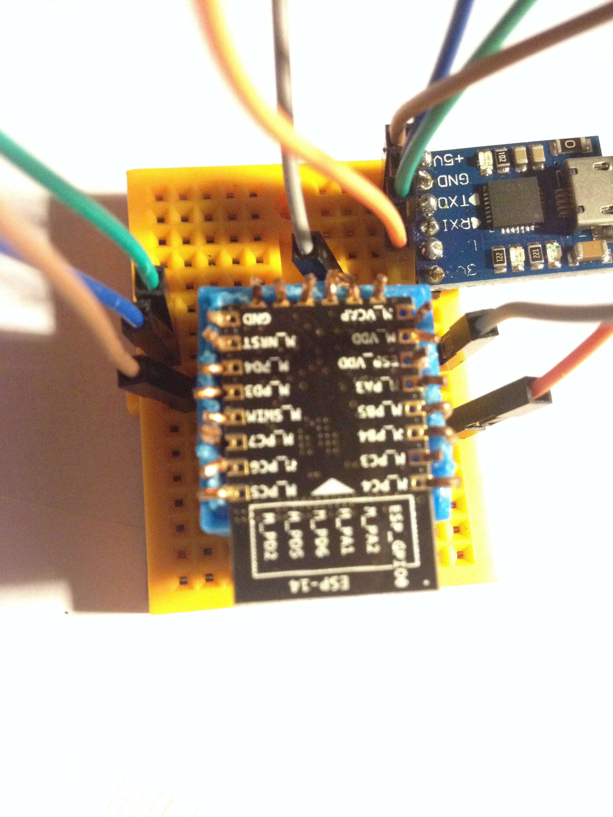
03/21/2017 at 11:36 • 0 commentsThe basic GCODE interpreter is about 90% coded onto the STM8 part of ESP14, with considerable thanks to @Thomas for his STM8EF forth interpreter. The comms part is also about 90% done on the ESP8266 part, with thanks to zeroflag for his punyforth. So here is a photo of the breadboard of ESP14 being programmed. Still running code in RAM until it works fully.
![]() Now, my job is to get back to the motor driver and get it to communicate with this ESP14. Since ESP14 is a wifi access point, I just need to connect ESP12 as dhcp client and set up the tcp channel through a chosen port (that's relatively easy). And then it is just a matter of getting both ends to behave properly when something (temporarily) interrupts communication (and that is the hard bit).
Now, my job is to get back to the motor driver and get it to communicate with this ESP14. Since ESP14 is a wifi access point, I just need to connect ESP12 as dhcp client and set up the tcp channel through a chosen port (that's relatively easy). And then it is just a matter of getting both ends to behave properly when something (temporarily) interrupts communication (and that is the hard bit). -
Concept test for controller on STM8
02/27/2017 at 22:34 • 1 commentSometimes smaller is better. Thanks @Thomas for eForth on STM8. I've added the files to this project where I have tested the concept of using STM8 running eForth to be the controller for the RB3DP. The forward and reverse kinematics routines are tested, and a few GCODE commands are implemented. Stubs are used for actual actions, with text echo of internal commands.
Based on this test, RB3DP will accept GCODE in millimeters and have a maximum size of about 60 meters (the 16-bit integer maths maxes out at 65.535 meters).
Now to put it all together on ESP14 (which is STM8 with ESP8266).
-
ESP14 as GCODE interpreter?
02/23/2017 at 07:12 • 3 commentsRather than Arduino and ESP8266, I wonder if ESP14 might work as a GCODE interpreter. Mmm...looks like a job for Forth, so I got hold of eForth (for the STM8) from another hackaday.io project (thanks to Thomas @TG9541 - see https://hackaday.io/project/16097-eforth-for-cheap-stm8s-value-line-gadgets). It looks like the GCODE interpreter is going to be about 3K of code on top of about 4.5K of eForth. Not a fancy interpreter by any means but it'll work (I believe).
I decided to implement each GCODE command as a Forth word. For example, the GCODE M17 command is to enable the motors, and has no parameters. Its implementation is trivial, as follows:
: M17;
  \ enable motors
  motorsOn
  ;
GCODE interpretation rules generally say to quietly ignore any GCODE command that does not apply to the particular machine, but Forth typically aborts operation if an unknown command is received. So, we want to change the outer interpreter. This is easy in eForth, thus:
\ GCODE interpreter
\ no prompt; ignore undefined words
: GEV ( -- )
  NAME? IF EXECUTE ELSE DROP THEN ;
and include the following in the initialisation routine\ change interpreter over for GCODE ' GEV 'EVAL !The forward kinematics and reverse kinematics routines are coded but untested. I've had a lot of fun with VARIABLEs and have finally reached a good way forward for this project. Just a little more coding and then some serious testing on ESP14, with both CPUs running Forth. Now that will be fun! -
Comms between Arduino and ESP12
01/26/2017 at 09:24 • 0 commentsI looked at I2C, Serial and SPI. The final choice of ESP12 as SPI master and Arduino Nano as SPI slave is perhaps somewhat non-obvious when you consider that the highest level controller is the Arduino Nano. Here's what I learnt from researching and my conclusions about communication between ESP12 and Arduino Nano for this project.
I2C/TWI
[The Arduino] Wire library has blocking I/O. That means, it goes into a busy loop and waits for the I2C communications to complete. Your application can do nothing while the TWI hardware is talking over the I2C bus. The maximum length of a 'message' is 32 bytes. The time to send just one byte is something in the order of 28 microseconds per byte using the maximum SCL rate of 400kHz (plus an extra byte for address).
Summary: A 32-byte message takes about 1 millisecond, which equates to about 0.05mm for an effector moving at 50mm/sec. I am not sure about the effect of blocking I/O though, when getting GCODE input from either SD card or Serial.
Serial
Nano has only one hardware serial port. Software Serial cannot do the high speeds of the hardware port, and are (I think) blocking I/O. Hardware Serial can easily and reliably do baud rate of 115200 and probably much higher. The Hardware Serial is the default interface to a host computer and using it for interfacing to another microprocessor compromises the ease of host connection. Maybe using the Software Serial for host connection might be workable.
Summary: Technically workable and faster than I2C.
SPI
Maximum speed is the clock speed of the slower partner (16MHz for Nano). Maximum transmission length is 64 bytes of data. NodeMCU does not yet support slave mode SPI on ESP8266. SD card readers typically use SPI, so may need to look in detail at timing for multiple SPI interfaces on the Nano.
Summary: Initially, it seemed obvious for the Nano to be the SPI master since it processes the GCODE and would ask ESP826 to do work for it. However, it might just be better to have the ESP8266 have the SD card reader and be the SPI master sending the GCODE lines to the Nano for handling and getting back the WiFi commands to send to the motors.
Grand Summary
ESP8266 is faster clock (80MHz) so can handle its work 5 times faster than the Nano (16MHz), so how about we load it up with what it can do best. So, the ESP12 can have the high speed stuff of reading SD cards and sending WiFi. That means we use the Nano as slave SPI and does the distribution of work. Perhaps not an obvious choice, but it should be interesting to put together.
PS Comments and any alternative suggestions are always welcome. Even better might be to put together your own project on Hackaday. You'll probably be quicker than me anyway; I am a slow coder.
-
ESP12F/NodeMCU memory shortage for controller
01/21/2017 at 09:35 • 2 commentsThe controller code for interpreting GCODE lines works fine on my desktop (using ZeroBrane). The lua code even loads onto the NodeMCU on an ESP12F, but it complains about not enough memory to run.
After some research and careful reading of NodeMCU documentation, it seems I am asking too much of the ESP12F/NodeMCU combination. The device really is an ideal IoT terminal node, but not really capable of parsing the GCODE and performing all the related tasks.
Oh well, looks like back to using an Arduino Nano clone and just using the ESP12F as the WiFi interface. I want to keep the Arduino serial IO for monitoring, etc. So, I now need to look at the best way to communicate between Arduino and ESP12F other than serial, then rewrite the Arduino code for the GCODE parser and WiFi interface.
At least, I've learnt lots about the ESP8266 and the ESP12 in particular, plus got a non-trivial Lua program to work (if only in simulation mode).
RigTig's Big 3D Printer
A DIY 3D printer (big volume, inexpensive, lightweight and portable).
 Now, my job is to get back to the motor driver and get it to communicate with this ESP14. Since ESP14 is a wifi access point, I just need to connect ESP12 as dhcp client and set up the tcp channel through a chosen port (that's relatively easy). And then it is just a matter of getting both ends to behave properly when something (temporarily) interrupts communication (and that is the hard bit).