-
1Prepare the CNC Files
The construction work of the CNC machine is pressing go on your CNC machine. But as anyone knows, CNC work is 95% setup and 5% cutting! A few words on setup are important here.
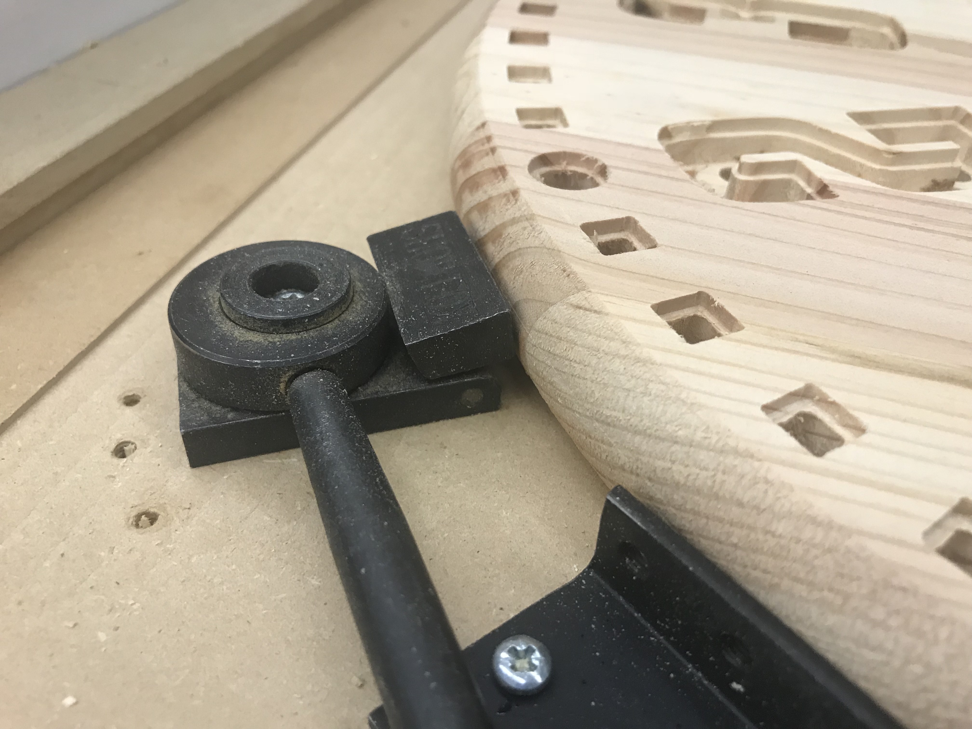
First, getting a solid fixture is essential. I am choosing to hold down the wood blank with these cam clamps. They work amazing and are very strong! So that they do not damage the wood, I put some small pieces of rubber between the contact area and the wood (this will not reduce the clamping force). Beyond being incredibly strong, another major advantage of these clamps is the fact that the total height of the clamp is below the work surface so there is never any danger of collision. If you do not have these clamps available double-sided tape can work. Whatever your method, ensure strong hold-downs and proper grain alignment.

Important Note: You will have to flip the clock and CNC both side of the machine so make sure you index your piece of wood. Make sure you can flip it and be EXACTLY in the same place. This is essential for cutting a good clock!
Now for some notes on the CAD and CAM work.
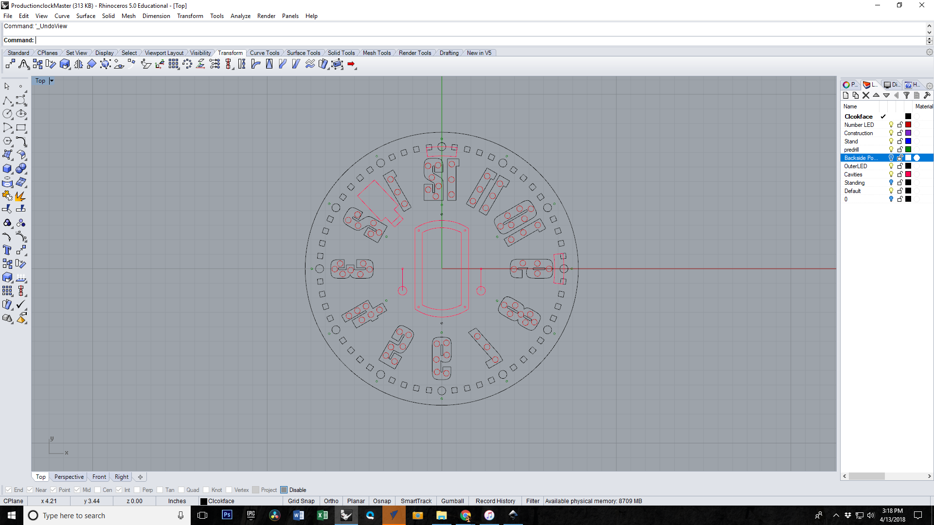
The Cad File (ProductionClockMaster.3dm) is a Rhino3d file and has all the necessary CAD layers for the clock. If you need a more generic format, I've also included a *dxf export of the front and back layers of the clock. This should be all the information you need.

The CNC CAM work is broken down into 9 separate CNC Operations. The actual Mach3 gcode files are included in the GitHub repository as well as the VCarve Files that produced them (if you need to open them and export using a different post processor).

All files for the project are available on GItHub. Here is how to interpret the files. They are relatively self-explanatory but here's some additional help to clear up any possible confusion. The first five files are listed in order of cutting operation. The file name ends in parentheses with the size of the cutting tool. So for example - 01_Rear Pockets_v1.8_(1-2 inch)
- This file name begins with 01 so it is the first operation.
- It will cut out the rear pockets.
- This is version 1.8 (I started with 0.0 so that tells you how many mistakes I made!)
- Use a 1/2 inch cutting tool
In addition to these five wood-block operations, there are two stand operations, an acrylic element operation and a back cover plate operation.
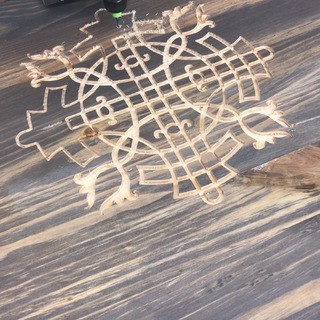
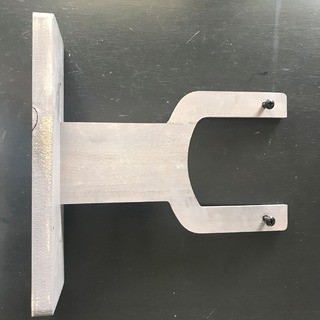
One operation that is unique is the T-slot CNC operation. This provides a channel for the bolts on the desktop stand to slide into. You will need a T-slot bit like the one shown in the photograph above.

Again if you need something other than the standard Mach3 post processor open the VCarve files and export in your local format. The next step we will actually walk through cutting the core and illustrate step by step what the clock should look like at each stage.
-
2Cut the Clock Core, Desktop Stand, Acrylic Tiles and Backing Material
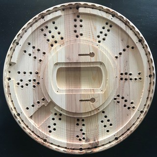
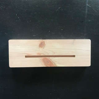
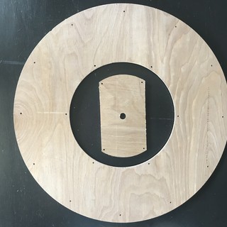
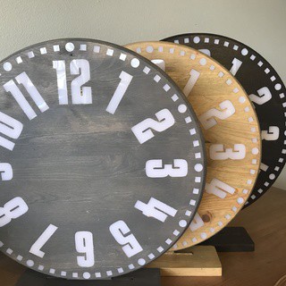
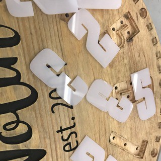
Here are some photos of each of the completed pieces as they come off the machine.


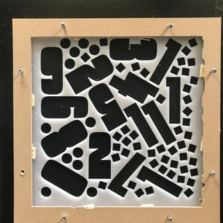
The acrylic is the most challenging cut since acrylic has a tendency to melt if it gets too warm and it also chatters and lifts if not held down securely. A laser cutter would be ideal if you have one. As you can see in the photo, I made a special jig that holds down all four sides tightly.

Double sided tape would probably be the absolute best for this operation but would be a little more time consuming to remove.
-
3Customize With Clock Face Art and Finish
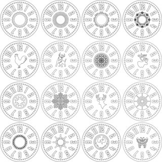
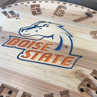
The clock can be used just fine without this step but it's fun to customize it according to your needs or tastes. We've tried a lot of different designs and the sky is the limit here. We'd love to see examples of things you come up with!


In terms of finishing we have tried lots of different things but love the simplicity and ease of staining. We also love General Finishes topcoat as it is particularly easy to install, durable and looks great! Now's the time to do that before we start installing electronics.

Tip: Don't forget to also stain the desktop stand, backplate plug and backplate at the same time. It's easy to get carried away and forget these accessory pieces!
-
4Acrylic Tiles and Stand Assembly
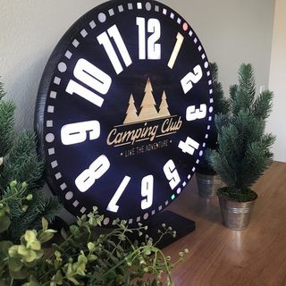
After you apply the finish to the wood pieces, it's time to press in the acrylic tiles and assemble the stand. The acrylic tiles are press fit tolerances and don't require any adhesive generally speaking. A few of the tiles may need small amounts of sanding or filing but generally, these just press in place and you are good to go. If you find that some of them are too loose and fall out, we use a few drops of white Elmers school glue as this is easy to apply, dries perfectly clear and provides plenty of adhesion. The front of your clock is now COMPLETE! Stand back and enjoy.

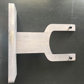
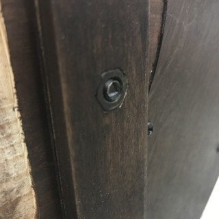
Also at this time you can also press into the stand the 1/4-20 nuts and lace in the bolts that slide down the T-slot channels. Drop the stand into the base with a little glue and your desktop stand is now ready!


-
5Install the Pre-Wired LED's Into the Clock Core
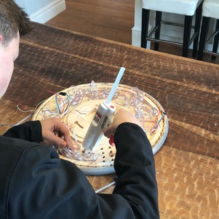
Okay, we are getting close! Probably the most time-consuming part of the clock is pressing in the individual LEDs. There are a total of 100 LEDs in this part of the clock and since the LED's come in strips of 50 you will need two strips that are connected end to end. The tolerances of the LED cavities are such that they are basically press fit. Even though the press fit tolerances hold the LED's in place, we use a small dab (very small dab) of hot glue to provide extra security. Too much glue and the excess will squeeze out and block the LEDs.
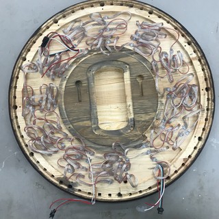
After this step you will have many loops extruding from the back of the clock that will need to be pressed down in order for the back panel to fit in place. A bit of hot air from a hairdryer makes the wires more pliable and easy to bend down. Again, using hot glue keeps these wires secured.


All told, this process takes about 45min to an hour. See the pictures above to see what this step should look like. Also watch the fun time-lapse video! If only we could wire that quickly!
-
6Assemble the Electronics
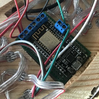
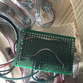
The electrical wiring is about at is easy at it comes but here's a detailed explanation. We found the easiest way to wire is to use a 4cm x 6cm proto board (the size of the CNC cavity) and install screw terminals that will receive the LED strips as well as the DC power adapter. We tried soldering in a more direct fashion and not only is this cumbersome and difficult, but it makes it impossible to remove or replace the guts of the clock in the event that the ESP8266 breaks or needs upgrading. Using headers is more flexible and, we think, easier.
Once the screw terminals have been installed simply follow the wiring diagram to connect the terminals to the correct pins. There are no actual components on the PCB, only traces from the headers to the appropriate ESP8266 pins.

Pin 4 is the pin for the ring LEDs and Pin 2 is the pin for the numbers. Positive goes to VSS and Negative goes to ground.

The only other thing that is needed is a 300ohm resister on the data pin of the LEDstrip. In every WS2812b strip I have ever seen (and I have seen lots) this is the center pin. This resistor protects the strip from danger voltage spikes and surges which could cause either damage or unpredictable behavior. I have neglected to install this resistor and have burned out the first LED on the strip (other times nothing happened and it worked perfectly). The resistor should be added inline which means that it functions like a link in the chain connecting the board to the wire to the LED. Some LED strips have these resistors already installed and some do not. If you are not sure if your LED strip has one, go ahead and add one anyway. There is not harm in doing so. Be sure to add this resistor inline as close as possible to the LED side of the connecting wire NOT the PCB side.
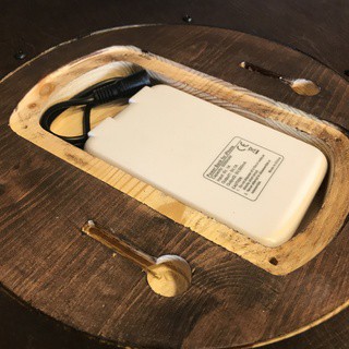
The cavity in the back of the clock is designed for two purposes. Either it can receive the body of a 5v transformer for wall mounting or it can hold an optional battery back. Illustrated here is a common 5v battery pack used to extend the range of wireless devices. Simply purchase a USB to 2.5mm adapter and your clock is now battery powered!

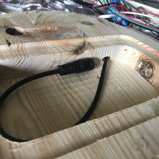
You will need to drill a hole from the center cavity to the PCB to receive the DC female pigtail. This is easily done by simply angling your drill bit. Be sure to stay shallow so you don't drill through the face of the clock! Shown is the completed drilling operation with pigtail wrapped neatly in the cavity.

-
7Upload the Code
The code for the clock can be found on the brightlightart github page.

The code is constantly being improved and is well-commented. If you are unfamiliar with *.ino files, this is an Arduino file format and needs to be compiled with the arduino IDE. Once compiled you upload via the standard microUSB jack on the ESP8266. If you need help with how to do this using the ESP 8266, here is an excellent tutorial on programming it with this popular interface. It's pretty close to out of the box but not quite!
What do these different files do? Here's a breakdown of the structure of these files and what they do in the big picture.
Webserver Folder
- Index.htm - When the code is initially uploaded to the ESP8266 you will be presented with an upload page asking you to upload a file. Upload the index.htm file. This file serves up the webpage - the other files in the folder are hosted on brightlightart.com but are here for your reference in the event that you want to change the stylesheets/javascript and host them yourselves.
Main Folder
- enLIGHTen-LED-Clock.ino - This is the parent file and originates from the excellent McLighting project. The script has been heavily modified from it's original state but we are indebted to this project as an excellent starting point for our project.
- colormodes.h - Handles most of the light animations on the ring. Also handles time functions.
- definitions.h - Defines most of the global variables.
- request_handlers.h - This communicates with the ESP8266 and handles incoming requests and sends information to the ESP8266.
- spiffs_webserver.h - Helps serve up and interpret the webpage. This is the only file with no change from the McLighting project.
- WS2812FX.cpp - Handles the light animations on the numbers. This is almost entirely taken from the excellent kitsurfer WS2812B library. The main change here is adding functionality for the hour hand to stay lit
- WS2812FX.h - header file that goes with the WS2812fx library. This is largely unchanged.
Additional Include Files
In addition to the files included here you will need the following libraries. These are standard libraries and easily included by searching within the IDE.
- NtpClientLib.h
- DNSServer.h
- FS.h
- ESP8266mDNS.h
- EEPROM.h
- WiFiClient.h
- Ticker.h
- WiFiUdp.h
- WiFiManager.h
- WebSocketsServer.h
- WebSockets.h
- ESP8266WiFi.h
- ESP8266WebServer.

-
8Initial Setup of EnLIGHTen Clock and Demonstration
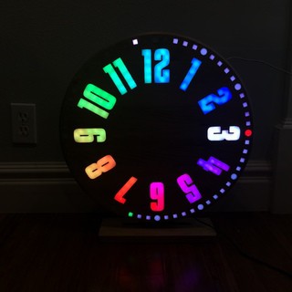
After uploading the source code and turning on power for the first time all the lights will be static blue. This is your indication that the clock is broadcasting an access point and waiting for you to connect. Using a phone, laptop or any wireless device, scan the nearby networks (like you would do if you were trying to connect to the internet at a coffee shop). In the list of available networks you should see one entitled "clock." Connect to it.
Once you connect to that network it will automatically load a webpage (again, like a redirect you would experience at a coffee shop). Be patient as this can sometimes take up to 30 seconds. The webpage will ask you to scan for nearby networks. Select your home or office network and provide it with the WiFi password. Once you click submit, the wireless password for your local network will be saved in memory. You will only have to do this once. The clock will reboot.
When it starts again, you will see it display a series of numbers in order. The numbers it displays are the IP address of the webpage you need to connect to. So for example it might display 1,9,2,.,1,6,8,.,0,.,3,1. This translates to http://192.168.0.31. Type this address into the webpage and you should now be connected to your clock. Configure away and have fun! Again, the clock uses websocket technology so any change you make should be reflected immediately without the need to press save or update the webpage. It's very interactive and fun in this regard!
If for some reason you loose connection, simply refresh your webpage. Most routers keep the ip address the same for connected devices but from time to time they do tend to change so pay attention on startup. If you need to be reminded of the ip address of the webpage, simply restart the clock.
Once you are comfortable with the code working don't forget to install the backing material! The predrilled holes make for easy alignment. Press down any wires that stand proud and now your wiring is secure and the clock is looking very finished!
-
9Build, Develop, Support and Enjoy
We would love to see as many people build and enjoy this clock as possible. We have loved this project and we want others to share in the experience! We have had so much fun solving problems, overcoming hurdles, squashing bugs and being rewarded by fun and meaningful light. The benefit we have received from the creative open-source community is priceless and has encouraged us to release this source material for shared learning, continued improvement, and technical enjoyment. We would love to hear about successful builds and ways you have improved the enLIGHTen clock. Please drop us a line and let us know!
Not everyone has time, skill, tools or resources to build one of these clocks from scratch so if you are interested in purchasing a completed clock either as a finished product or as a base for continued development please support us on Kickstarter.com
EnLIGHTen Web-Connected, OPEN source, LED Clock
A web-connected clock that automatically adjusts for daylight savings, visual alarms, and beautiful animations via an intuitive web page.



Discussions
Become a Hackaday.io Member
Create an account to leave a comment. Already have an account? Log In.