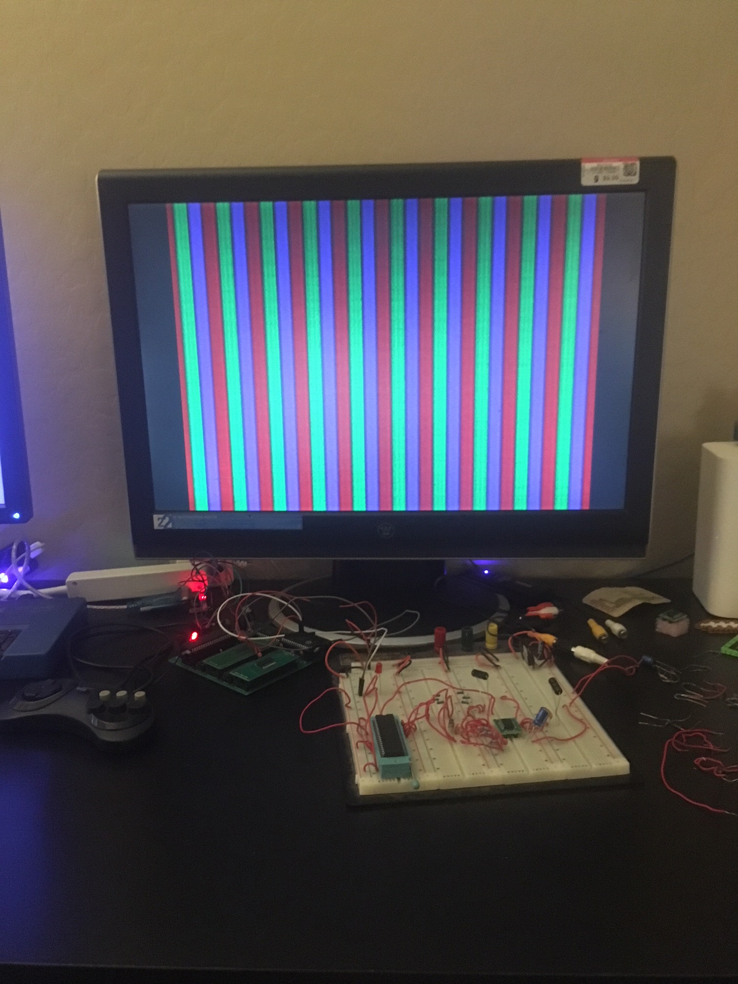
Well today I received my new AD724 chip, theoretically all I had to do was plug it in and replace the one I had blown and I'd have color bars... or cry salty tears because if it didn't work then I would have no clue what was going on, so I plugged it in and turned on the power!...
Nothing worked - blue screen (blue meaning the monitor had nothing to sync to).
So frustrating!!!!! I spent a long while pouring over the datasheet for the hundredth time... I had everything hooked up right... why was I seeing nothing? No wavy bars, no noise, just... nothing.
So I looked things over one more time... I noticed the capacitors to the color input pins were hooked up wrong. They were supposed to be hooked up in series... but I actually wired them in to the breadboard in such a way that they would have no effect. I dunno, I was probably tired and those holes are so tiny they always just look correct... embarrassing I know. But these were just for the color inputs - theoretically I should have AT LEAST been seeing black and not a blue no-sync screen right? But... you know, desperation and all...so I wired them up correctly and turned on the power...
OMG IT WORKED I SEE COLOR BARS!!!!!!

I actually thew off my headphones and screamed to my wife "oh my gosh - color bars!!!!!!"
The bars are R,G,B - the next step is to get a DAC and use it to vary voltage signals to the color pins so I can send my 4-bit color palette: R, GG, B - hopefully the next screenshot I post is 16 different colors instead of just red, green blue.
An interested reader here will wonder, well was the original AD724 blown or was it incorrect capacitor hook ups all along? I wondered that my self so I put the original chip back in and boom - it worked perfectly. Ah well - now I have a back up :)
Next step is to order the DAC, hook it up, and modify the code to do 16 color bars. I'll post when I have an update, hopefully this weekend or next week!
Discussions
Become a Hackaday.io Member
Create an account to leave a comment. Already have an account? Log In.