Close
0%
0%

Adding AD7606 Module Arduino support in Visuino

AD7606 is a powerful 8 channel 16 bit ADC Module with built in Mux Sample and Hold Analog, and Digital filters and has no Arduino libraries

Similar projects worth following
Couple of days ago I received a great AD7606 Module donated by ICStation for the Visuino development. The module has great features however I was not able to find any Arduino libraries, so I am starting work on my own, and will post the progress here.

I received the AD7606 Module few days ago as a generous donation from ICStation for the Visuino development.

My first task was to research if there are any ready Arduino libraries or code examples for it. So far I have not been able to find any, so I am starting work on my own, and it will be included in the Open Source Visuino libraries .

I have already found documentation for the module and reading through it.

Since I will be speaking at 2 conferences in Europe - Germany and Netherlands later this month, and also working on 2 articles for the next issue of the Blaise Pascal Magazine, the work will take longer than usual, but I still hope to make some good progress in the gaps, and have a Visuino release with the support for the module before the end of the month :-) .

AD7606Test1.owarduino

Visuino test project for AD7606 and Arduino Mega

owarduino - 14.59 kB - 09/09/2016 at 21:22

Download

AD7606_7606-6_7606-4.pdf

The original AD7606 documentation

Adobe Portable Document Format - 915.65 kB - 09/06/2016 at 02:42

Preview

  • 1
    Step 1

    The AD7606 Module has 3 modes of operation:

    1. 16 bit parallel
    2. 8 bit parallel
    3. and serial

    This table shows the configuration options:

    As you can see, to use serial or 8 bit (Byte, 8080) mode, you need to connect the PAR/SER/BYTE SEL pin to +.

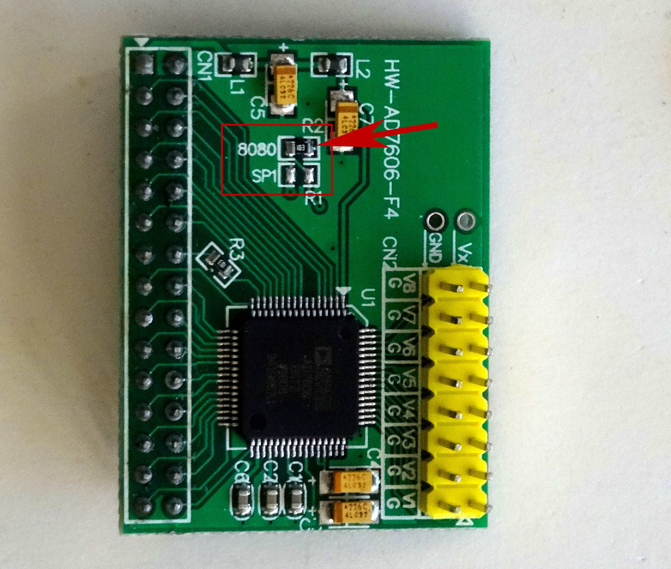
    The module has configuration resistors for this:

    The first problem is that the labeling is confusing. As we have seen in the table, in both the 8 bit (8080) and serial modes we need the pin to be connected to VCC. The "8080" label however is located next to the resistor connected to ground. When this resistor is placed, the module is firmly configured for 16 bit mode :-( .

    This is how the modules arrive configured from the factory. They are also incorrectly described as configured for 8 bit mode in most sites that carry the module.

    To switch the module to 8 bit mode or serial, you will need to move the resistor from the top to the bottom position on the picture - next to the SP1 label.

  • 2
    Step 2

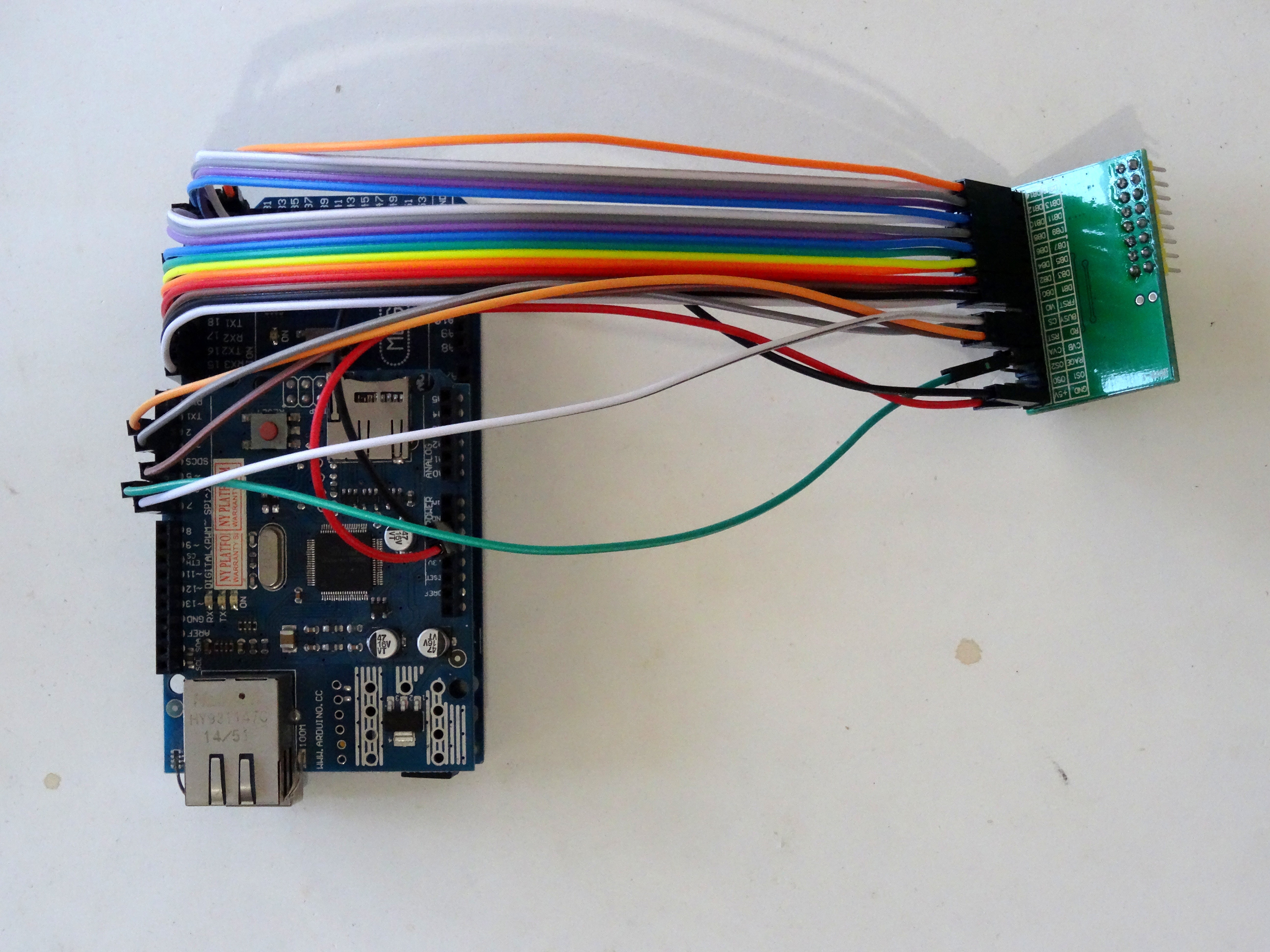
    The next step is to start connecting the module to Arduino. Since I will need 16 pins just for the data, and I still need to connect Reset, CS, RD and few others, I decided to use Arduino Mega. I have an Ethernet Shield installed on my Mega for other developments, and testing, so I decided to leave the shield in place for the experiment. Here is the result:

    Quite a mess, but holefully will work.

  • 3
    Step 3

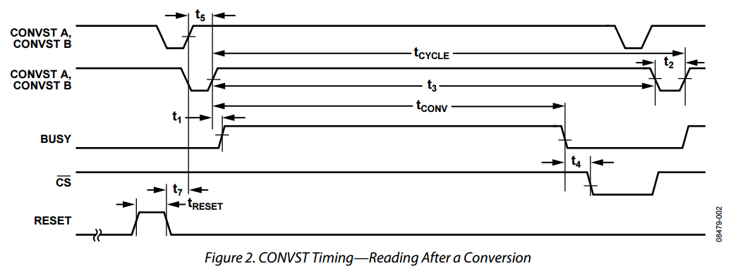
    To start measurement, you need to set the Convst A and Convst B to low. The 2 signals can be set at different time:

    However the Maximum time T5 between the 2 signals is only 0.5 mS . This makes it impractical for individual software control, so I have connected my 2 pins together, and in Visuino will implement them as a single control pin.

View all 6 instructions

Enjoy this project?

Share

Discussions

Boian Mitov wrote 09/29/2019 at 21:05 point

No, only with Visuino

  Are you sure? yes | no

henrique112 wrote 09/29/2019 at 20:57 point

Have you used this hardware with regular arduino coding?

  Are you sure? yes | no

Similar Projects

Does this project spark your interest?

Become a member to follow this project and never miss any updates