Close
0%
0%

Pi-Fi Drouter

A Raspberry PiZero based mobile router with wireless storage and memory expansion capability

Similar projects worth following
This project is a combination of a mobile hotspot and a storage device which can be accessed wirelessly. Also, the device can provide wireless access to any data storage device by simply plugging into it's USB port.

The project basically consists of the following components:

1) The brain, RaspberryPi Zero

The brain of the project is a RaspberryPi Zero. With its cost of just $5, it is an amazing processor and perfect for our application. It not only cuts our cost but also helps in avoiding an overkill of processor found in its elder brothers the RaspberryPi 1, 2 or 3.

The Pi Zero is configured to act as a Samba Server. The Samba Server provides the baseline for basic file transfers. This protocol is very convenient to use for our application as the user would be interested in reading a normal pendrive on-the-go or backing up his data from his smartfone on a pen drive, where does not have laptop access, just form the device.

2) The Comms, Wi-Fi/GSM module

Unlike Raspberry Pi 3, the PiZero doesn’t have a Wi-Fi module of it’s own. To equip the device with wireless capabilities, we shall use a normal 802.11 adapter. But instead of using 2 separate devices for wireless communications and a GSM gateway, we can use a normal Wi-Fi equipped unlocked dongle with interchangeable SIM cards. The advantage of having such a single Wi-Fi dongle is that we can relieve from the headache of routing the data packets from the GSM module to Wi-Fi which would be unnecessary overhead on the PiZero. Also, these dongles would have DCHP stacks which dynamically provide IPs, coordinate data packets and route it to Wi-Fi. The dongle is connected to the one of the four downstream ports of the hub internally.

3) The enhancer, USB Hub

The non-availability of more USB ports on the PiZero doesn’t limit its capabilities. Simply attaching a USB 2.0 Hub would easily work around the problem. Such a 4 port USB hub is designed for the device with minor modifications under the courtesy of Pi Angle Zero by Sean Hodgins. The hub’s upstream port is connected to the Upstream port of the PiZero.

4) The memory, Pen Drive

A completely body-stripped pen drive is connected to USB hub internally. Any normal pen drive would suffice but let’s stick to 16GB for time being. Furthermore, for memory back up or instant data access from a normal pen drive, without wireless access from a smartphone, the user can hook it up to the 2 external USB 2.0 ports provided.

5) The Display, Oled

Oled displays are being common these days due to its extremely low power consumption. These kind of displays are ideal for mobile devices. It displays the basic information such as battery percentage, signal strength, Wi-Fi signal strength etc. These kind of displays are accessed via I2C or SPI such as the 128x32 Oled Display from Adafruit.

oled.sch

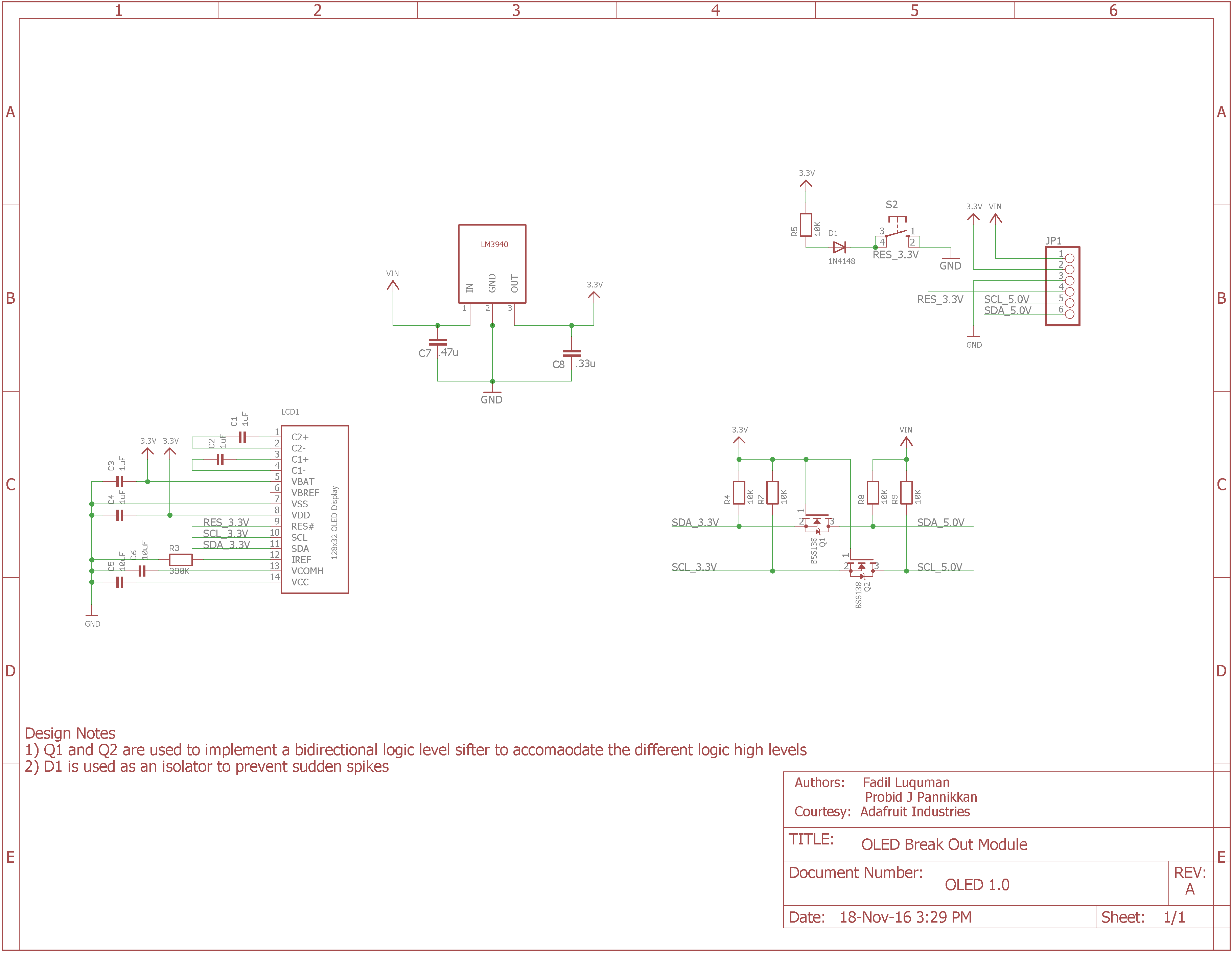
Adafruit provided an excellent schematic for the OLED break out module. I made some component changes and added some design notes for easy schematic analysis

sch - 244.81 kB - 11/18/2016 at 10:00

Download

usb_hub.fzz

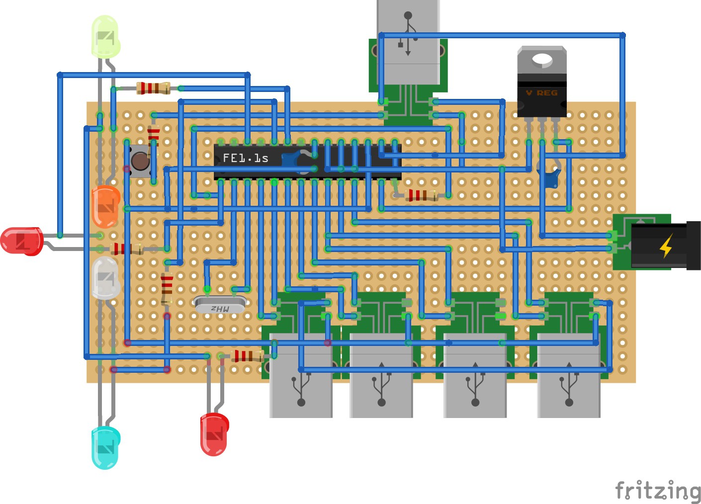
BreadBoard view usb_hub(just for fun)

fzz - 25.28 kB - 09/08/2016 at 09:47

Download

usb_hub.sch

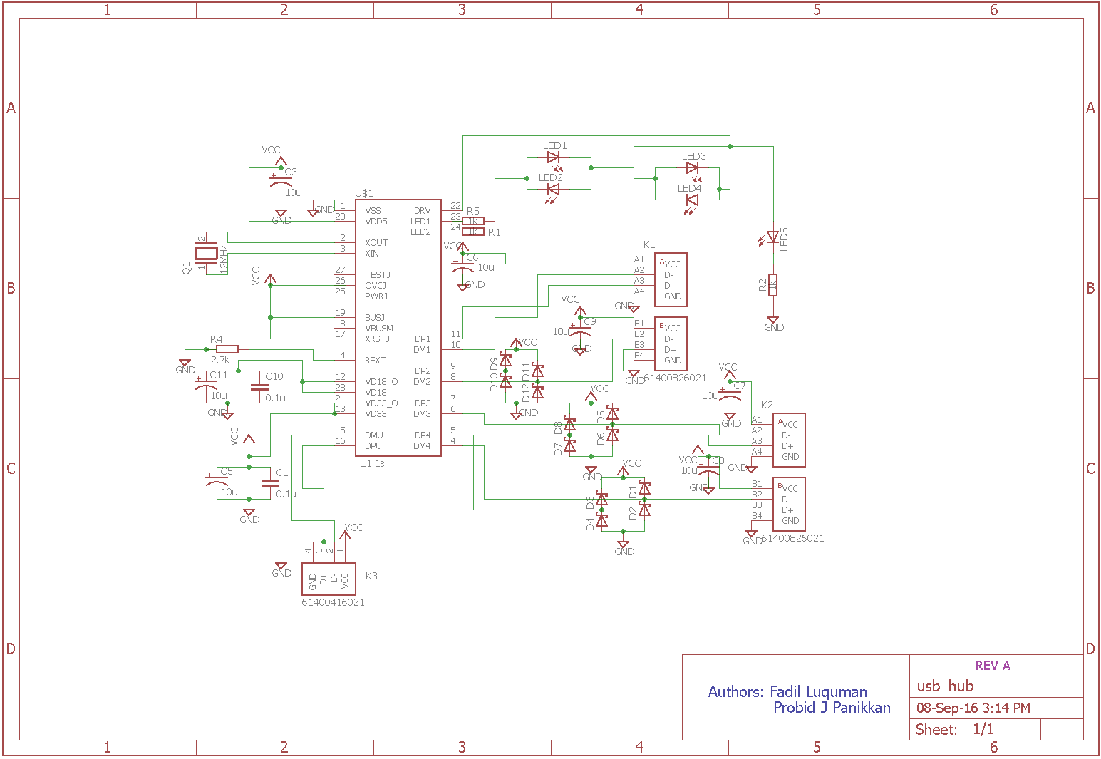
USB HUB REV A

sch - 657.16 kB - 09/08/2016 at 09:45

Download

View all 17 components

  • ​3) OLED Break Out Module

    fadilluquman11/18/2016 at 11:08 0 comments

    When it comes to mass production, it's best fit to design the whole board with discrete components rather than buying individual components, assembling and integrating them. It simply adds to the cost as well as space. Under Adafruit's courtesy, I have made a few changes with some components and added some design notes. The OLED module is pretty straight forward apart from the bidirectional logic level shifter. You can find more information about it in the following pdf: http://www.nxp.com/documents/application_note/AN10441.pdf

    Refer the following schematic for the same:


  • 2) USB Controller: REV A Schematics

    fadilluquman09/08/2016 at 09:44 0 comments

    Once the breadboard view of the controller was developed, I moved onto designing and developing the USB hub controller on Eagle 7.6 Lite. This software is a very handy tool for makers and hobbyists as it provides free license for up to 2 layers. This is more than enough for our project. There are other softwares which serves the purpose like OrCAD Lite. There is no time limit for this version but is limited by the complexity of the design like a design with more than 90 nets cannot be saved etc. I have been working on a custom library for the usb controller. The differential USB data lines require high speed TVS (Transient Voltage Suppressor) ESD(Electro Static Discharge) protection diodes. The TI TPD4E1U06 serves exactly this purpose. Hence, the REV A usb hub would look a little ugly due to the large number of TVS diodes. I have uploaded the REV A schematics which would be very shortly revised with the custom library part.


  • 1) USB Controller: BreadBoard View :P

    fadilluquman09/07/2016 at 12:16 1 comment

    Initially I started working with the USB Hub. I really have no clue why I started with it. But yeah, who knows. Any ways, before going to the actual schematics, I just thought to generate the breadboard view of the board. But yeah, it really doesn’t give feel of the hub. But yes, it does show how such a circuit rigged on the breadboard (perf board) would look like. I should tell you that there is absolutely no chance the board would do its functionality when rigged on the perf board as there are some considerations to be taken care about when laying out the differential signals of the USB upstream and downstream ports. Guys, just take a look of the Fritzing developed perf board view of the USB hub.


View all 3 project logs

Enjoy this project?

Share

Discussions

Similar Projects

Does this project spark your interest?

Become a member to follow this project and never miss any updates