Josh Starnes
-
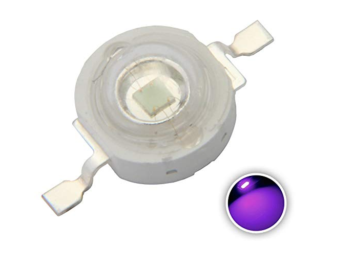
Upgraded LED Parts coming overnight
10/10/2018 at 19:38 • 0 commentsUV 3 watt leds and IR 3 watt leds are on the way as well as heat sinks to solder them too. I plan to use compass error correction for the heading between QR codes. I already have regular 5mm leds , but I need something a little bigger for ceiling reading clearly.
![]()
![]()
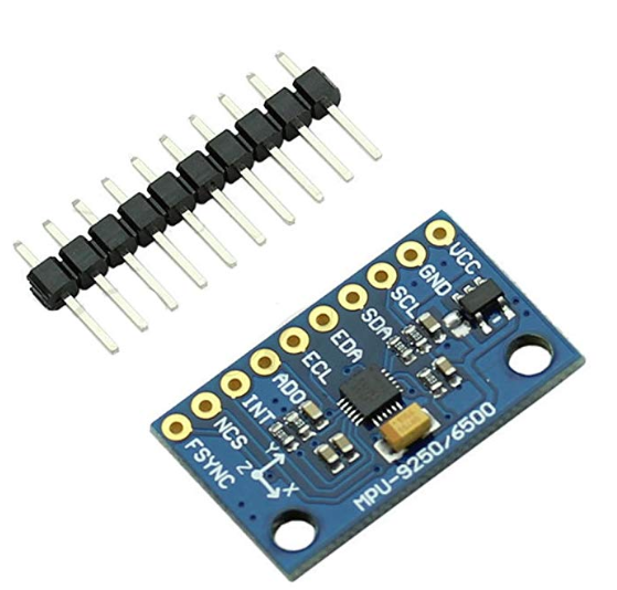
In addition to the LEDS, I ordered a compass module because I cannot locate the one I ordered for the project.
![]()
-
Rovio 2.0 progress, adding cameras
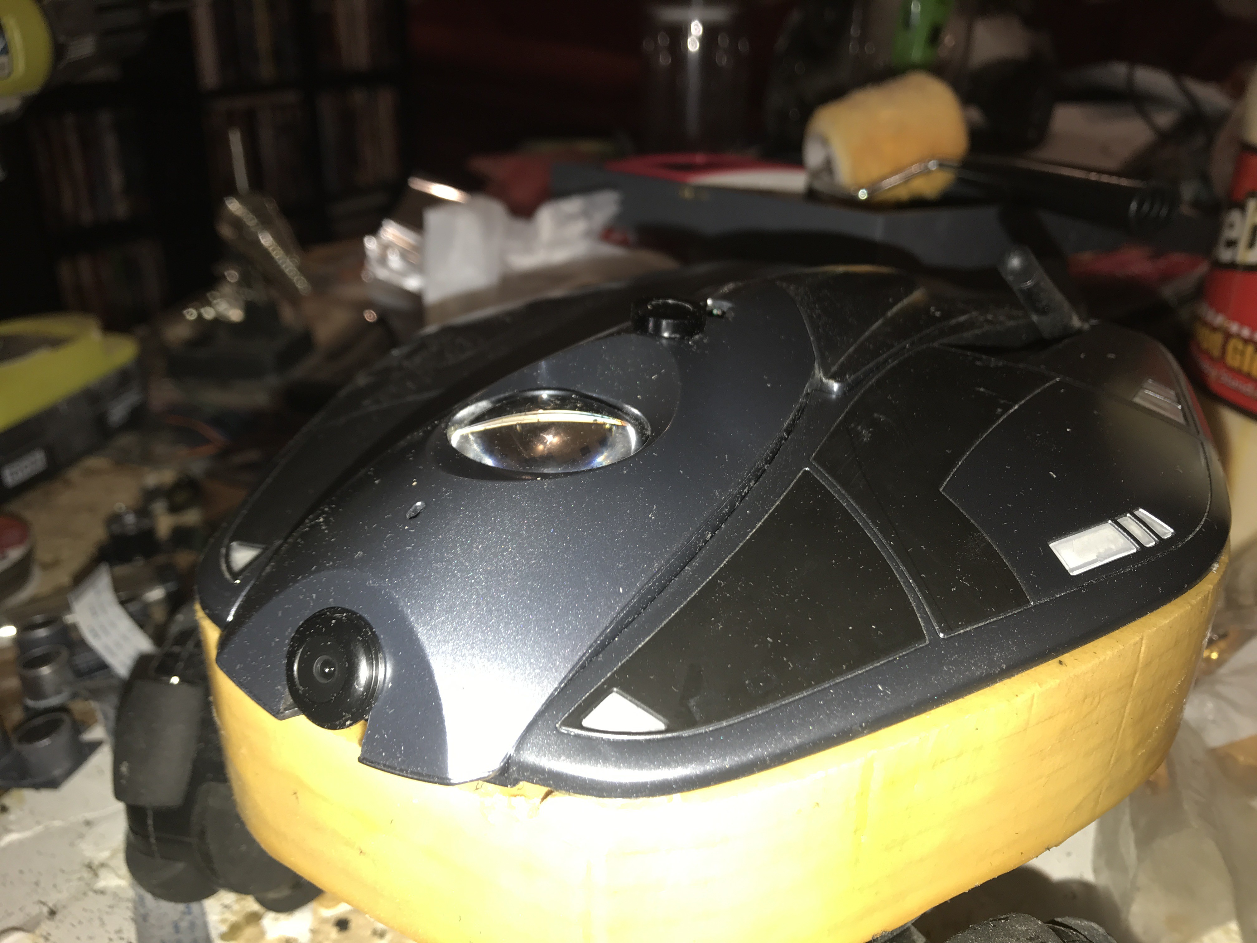
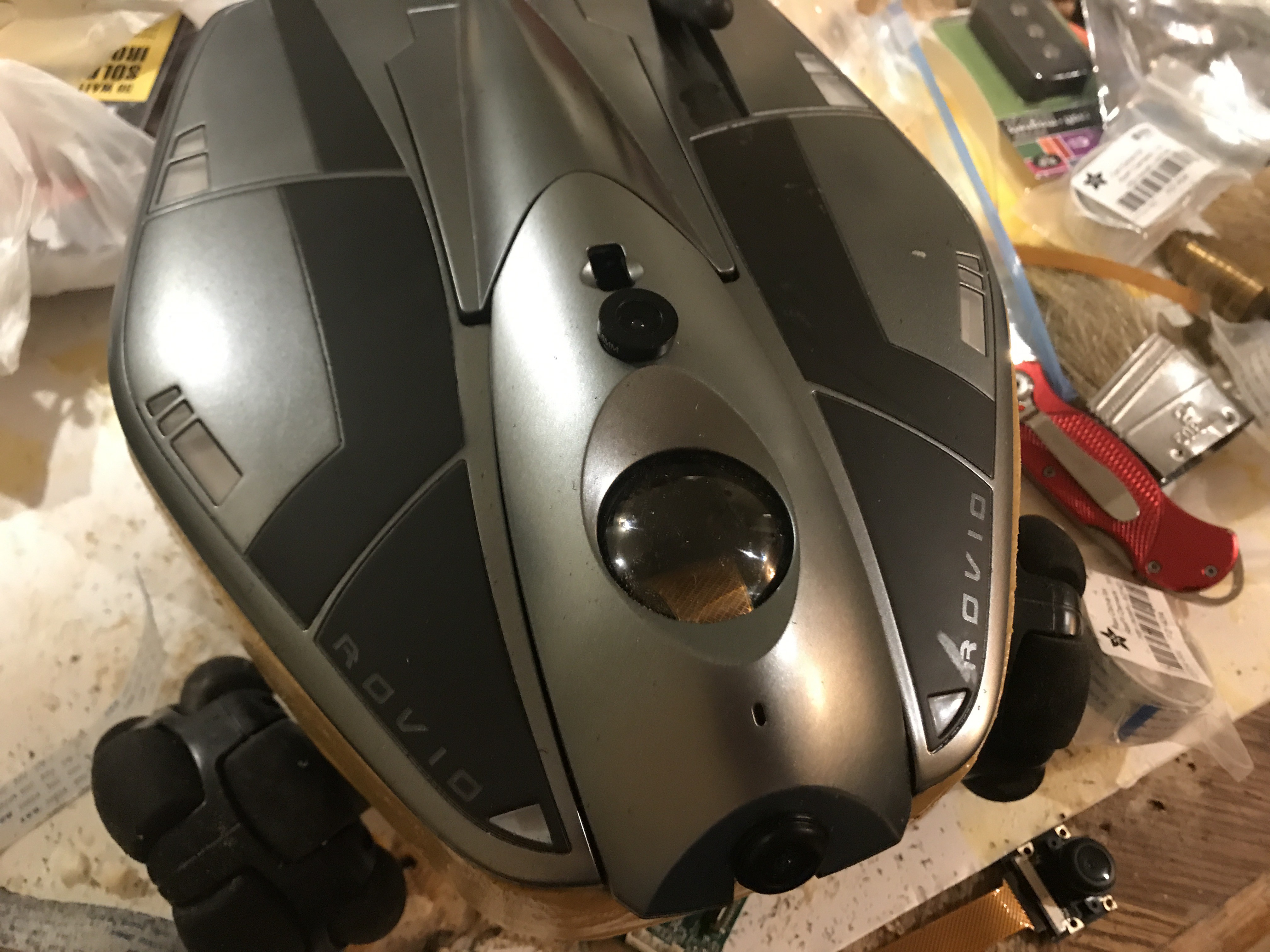
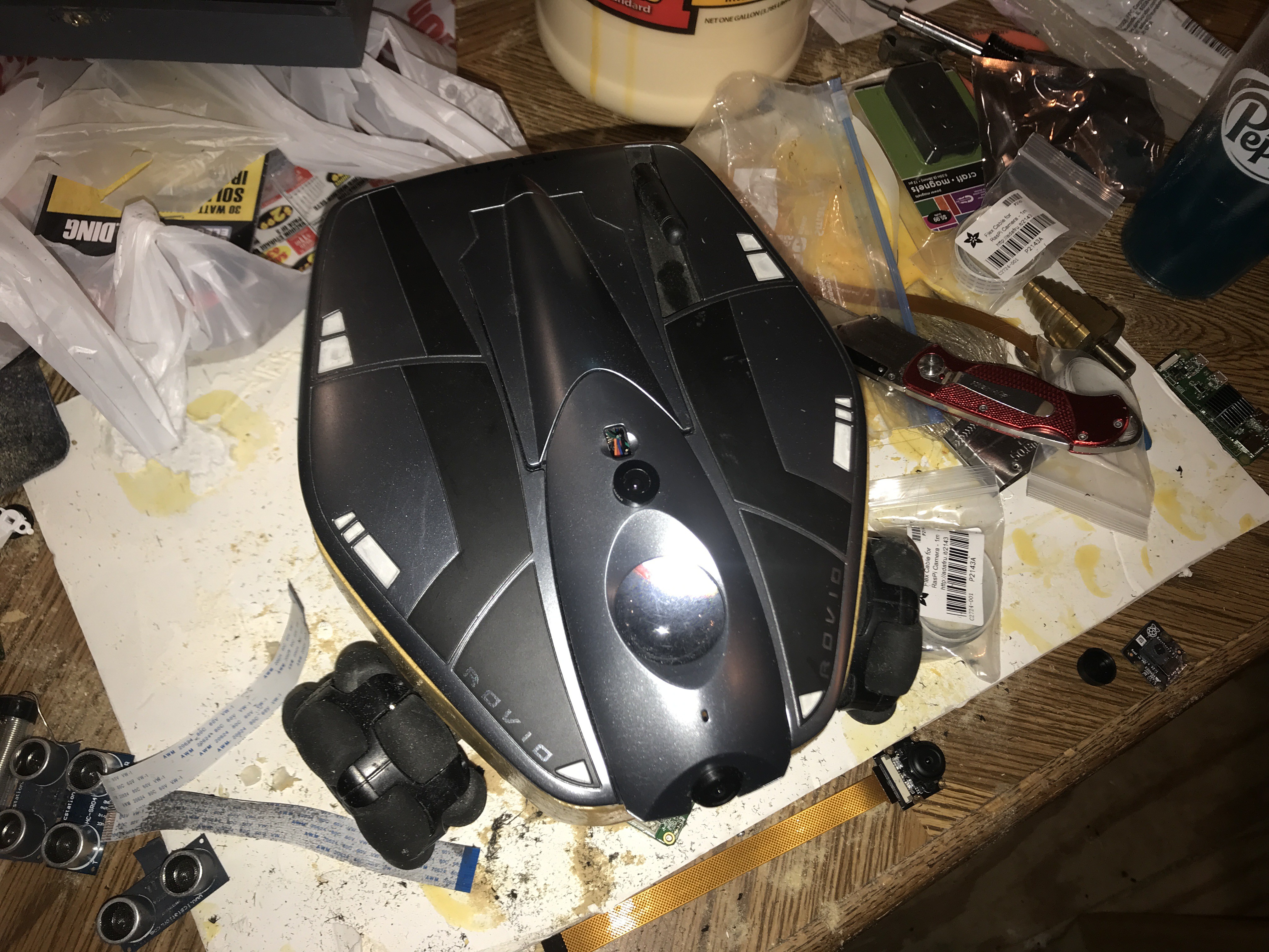
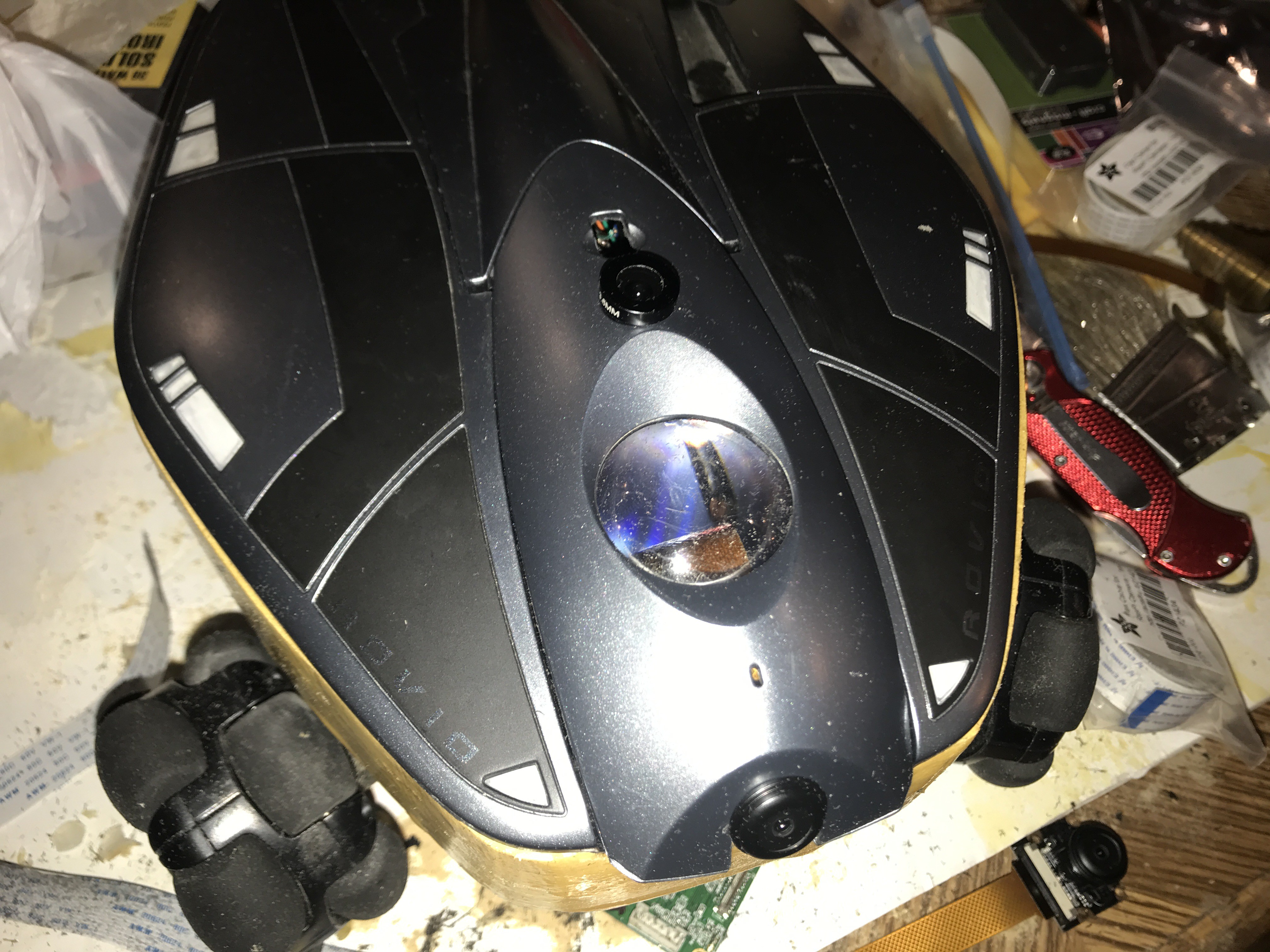
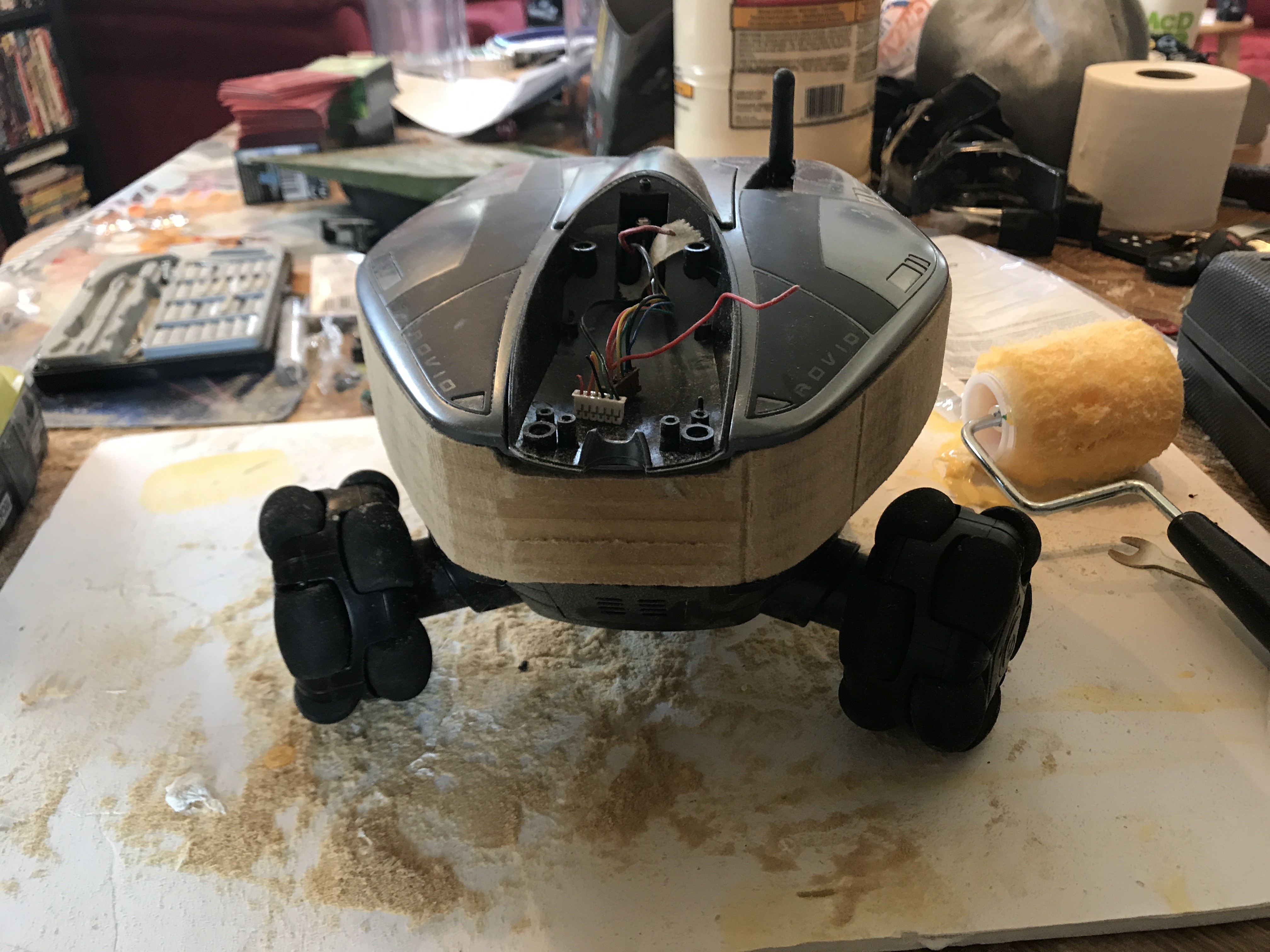
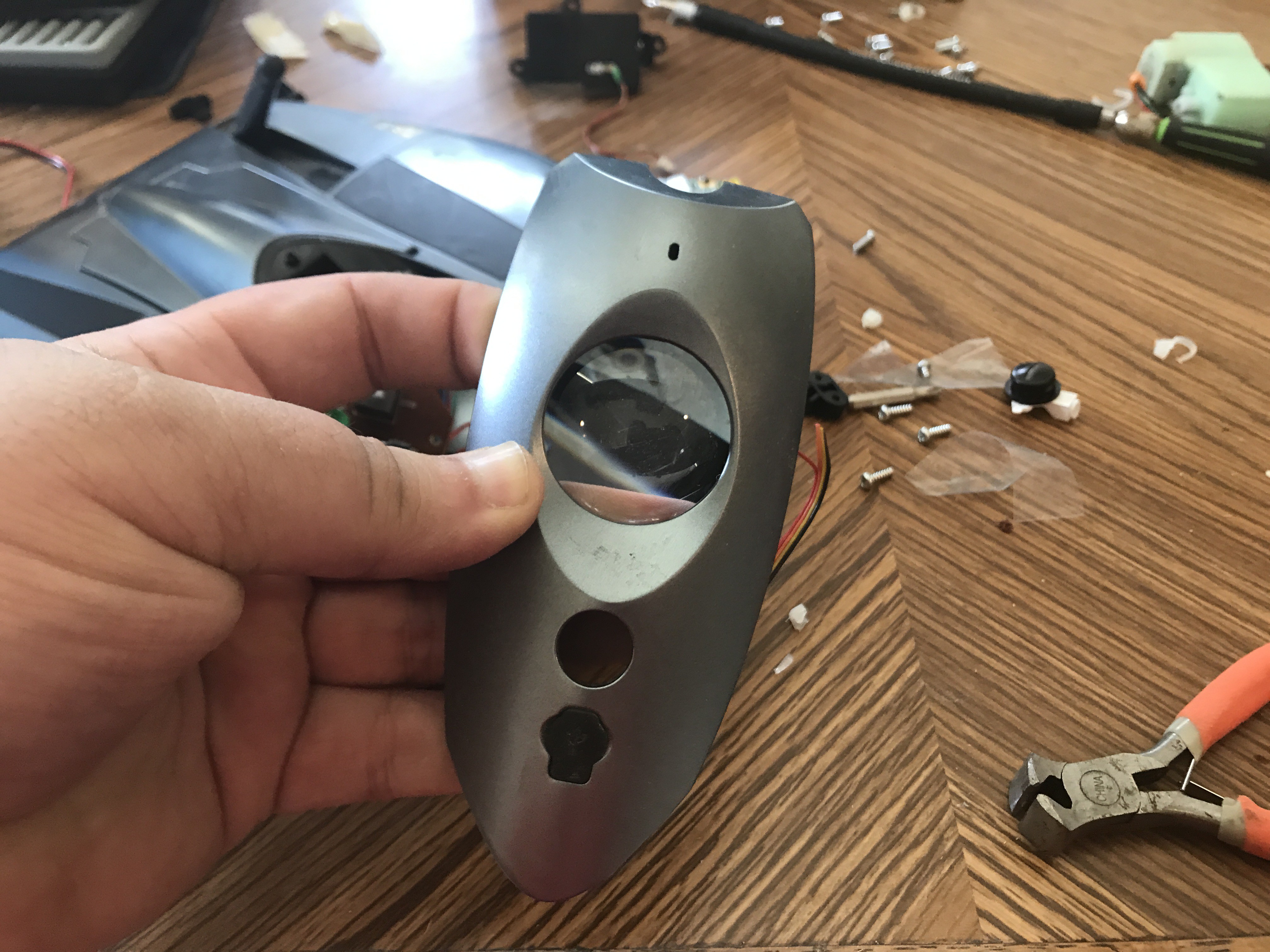
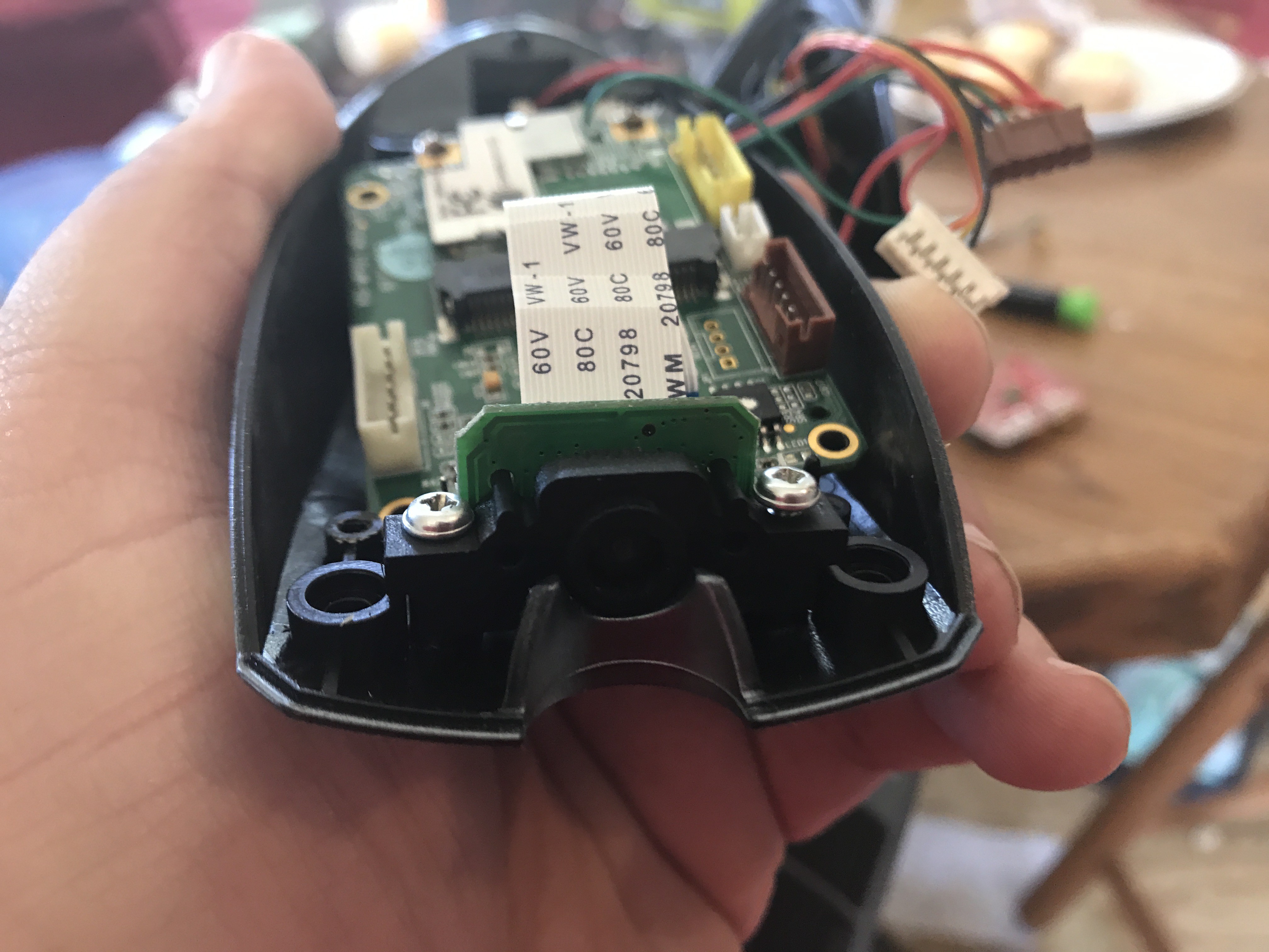
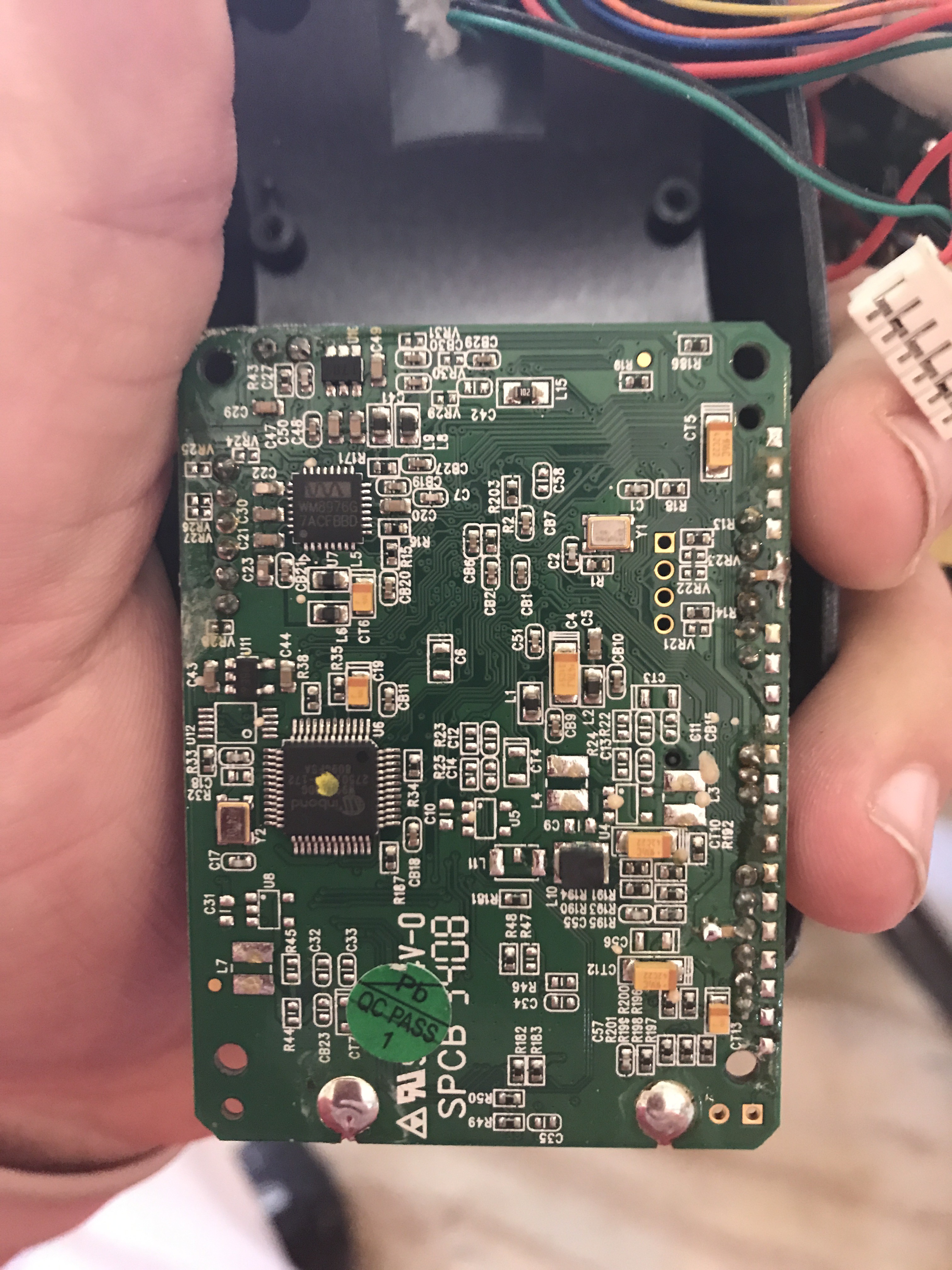
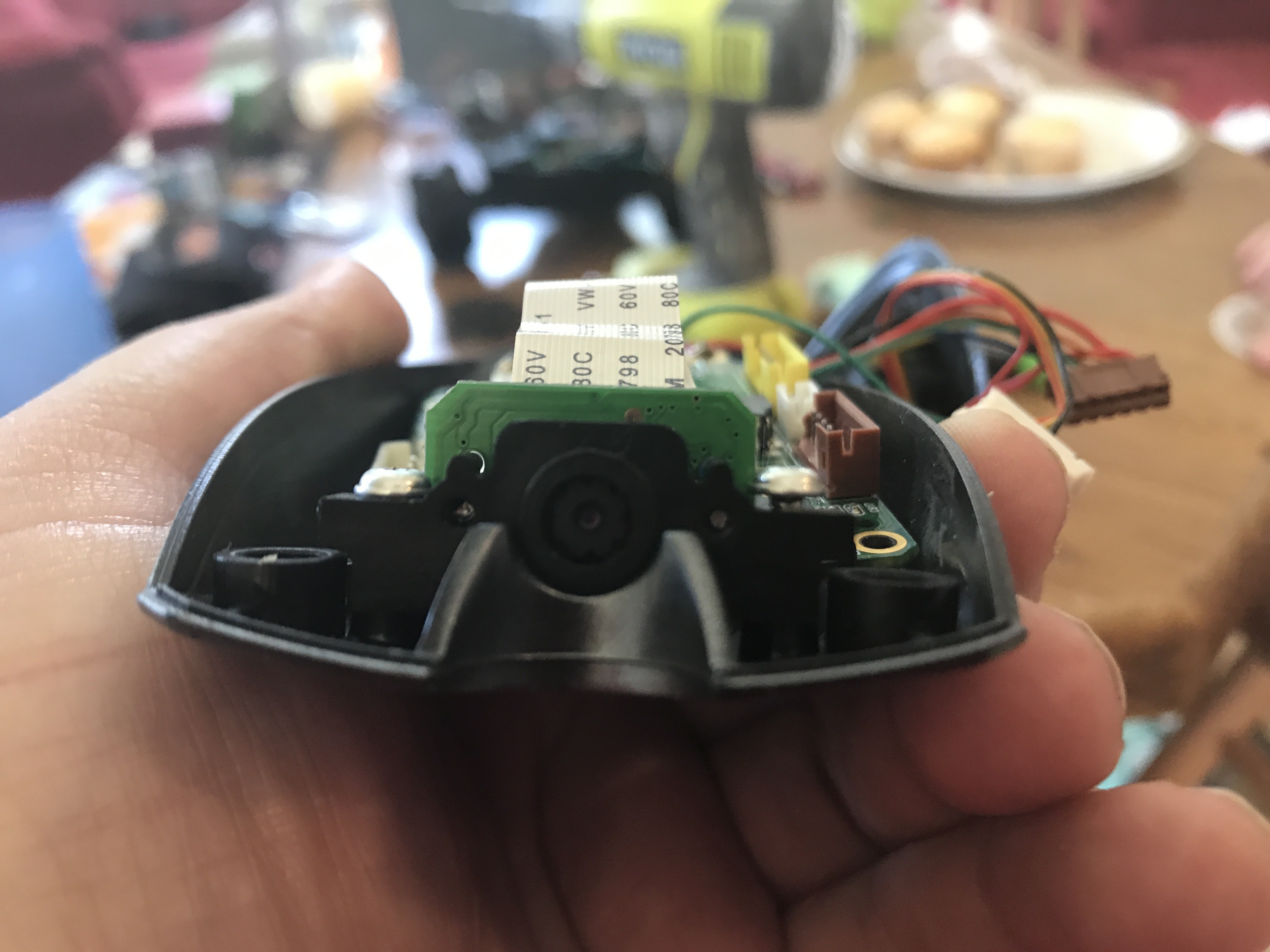
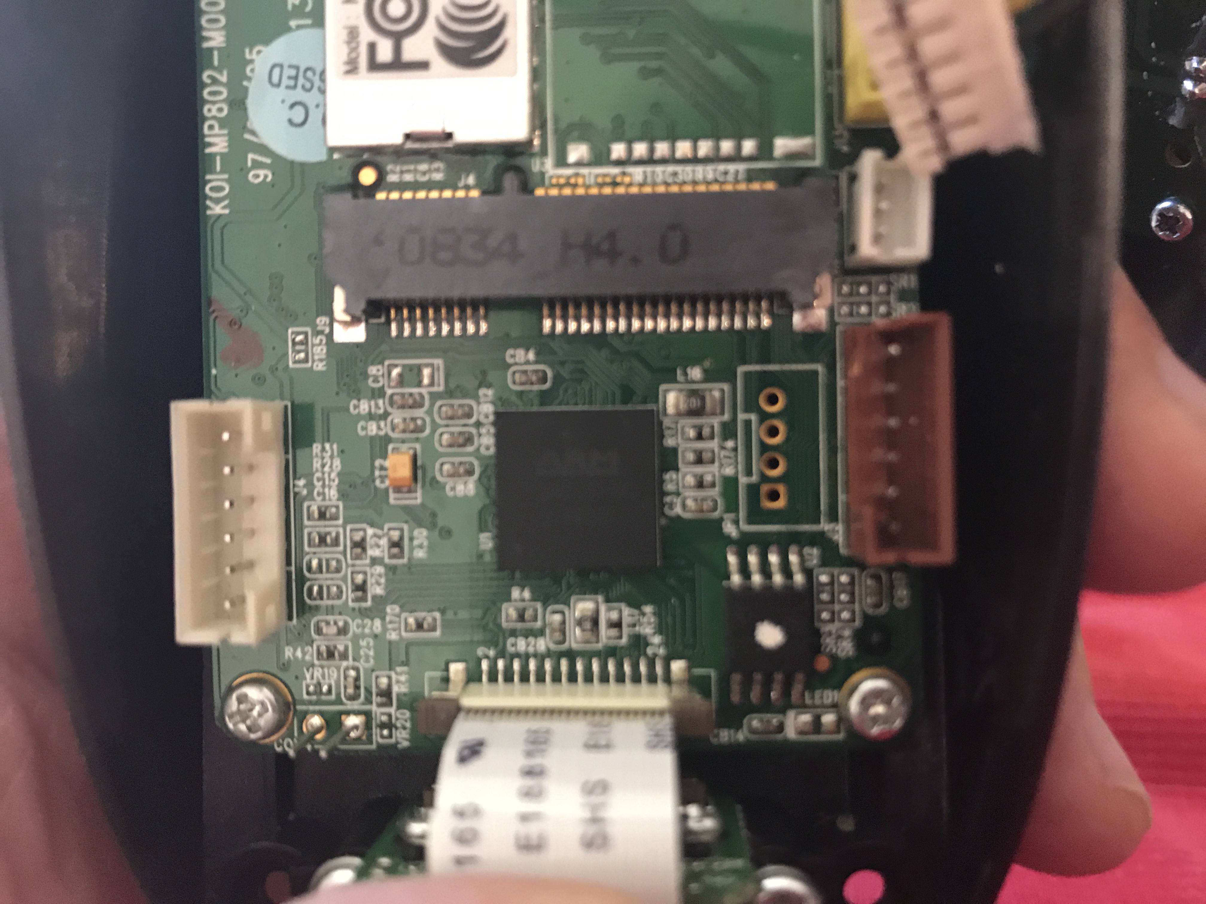
10/10/2018 at 13:11 • 0 commentsLast night progress was made in finding places for the modern HD cameras that are both forward facing and the ceiling facing as well. I have 4 different camera options so they are not set in stone ,but at this time I have the 120 degree cam facing forward 5mp no IR filter, the ceiling camera has a shutter to add to remove the IR filter as needed. You may notice a large 1 inch clear lens. This lens collimated light from smaller sources into a sort of dot on the ceiling that is more more defined with less energy.
![]()
![]()
![]()
![]()
![]()
![]()
![]()
-
Rovio 2.0 Riser/Spacer Progress test platform
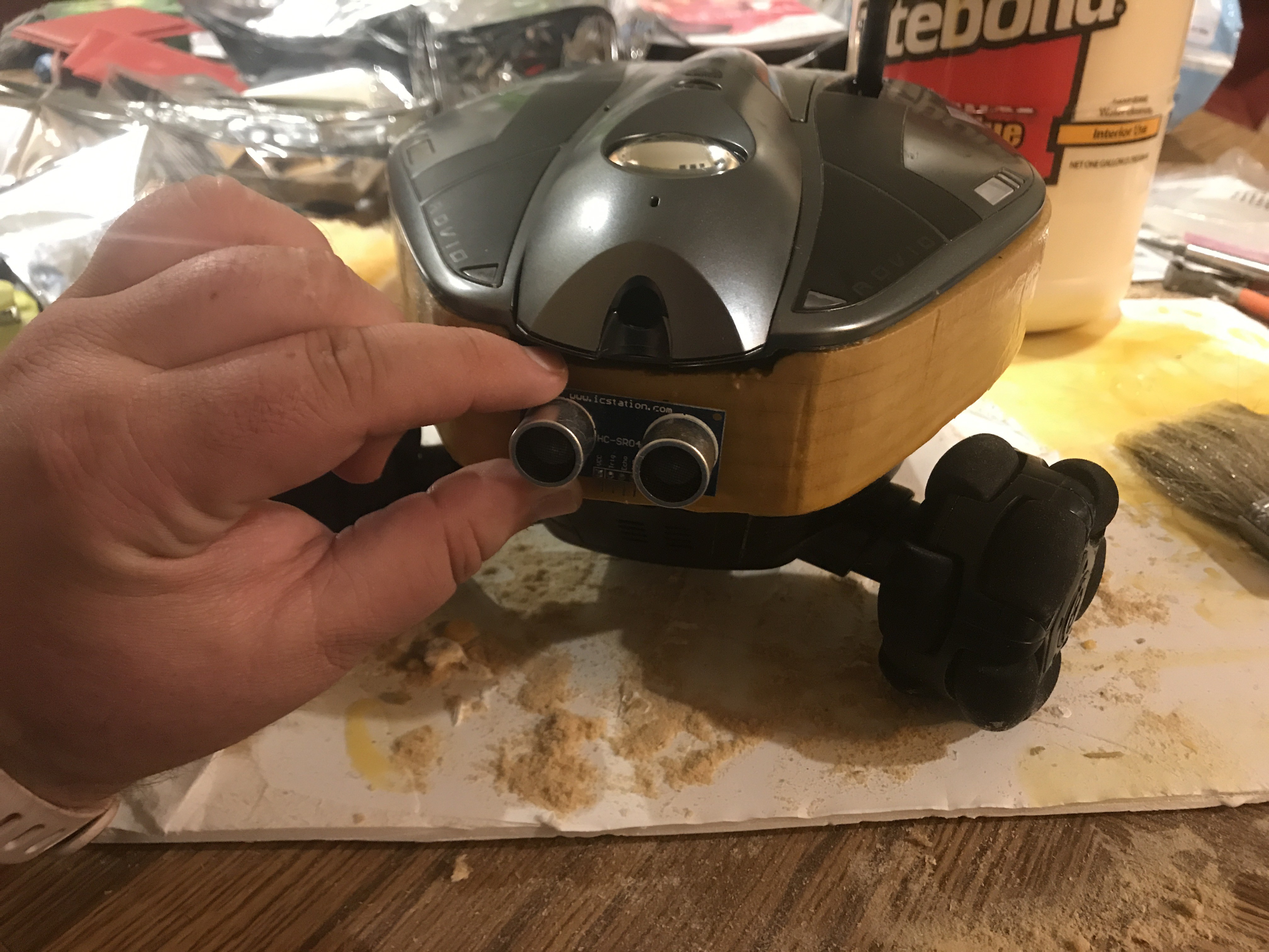
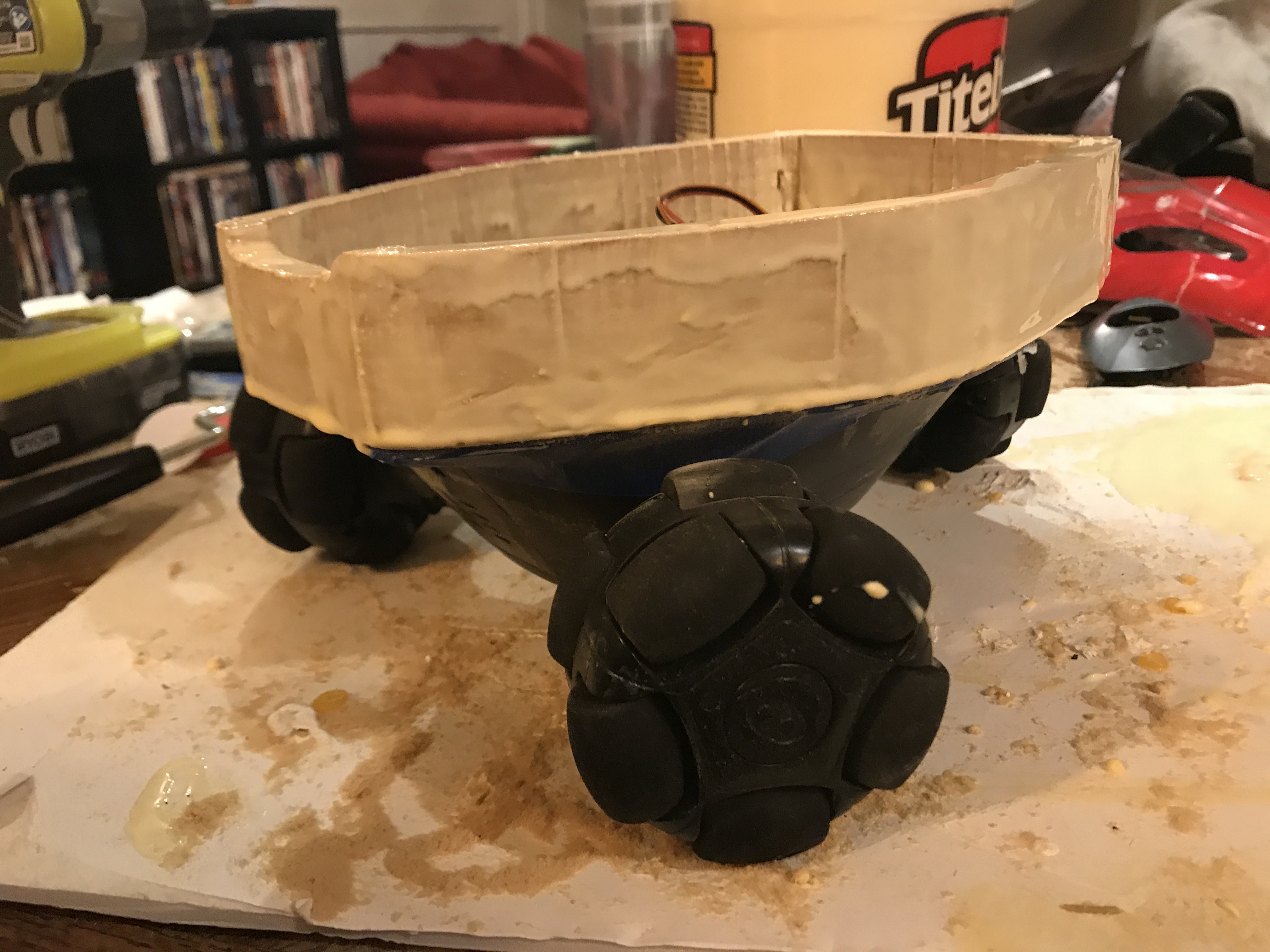
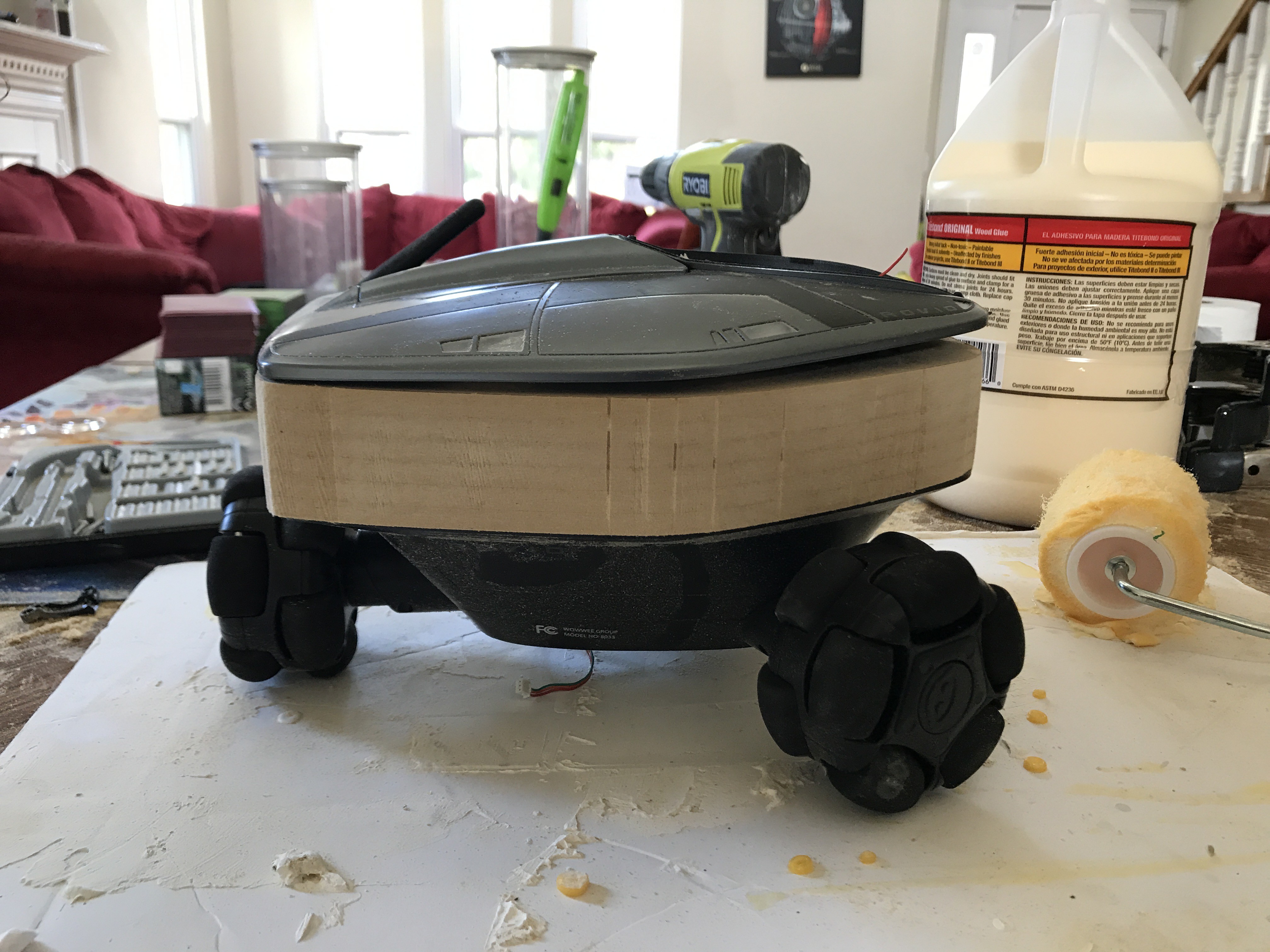
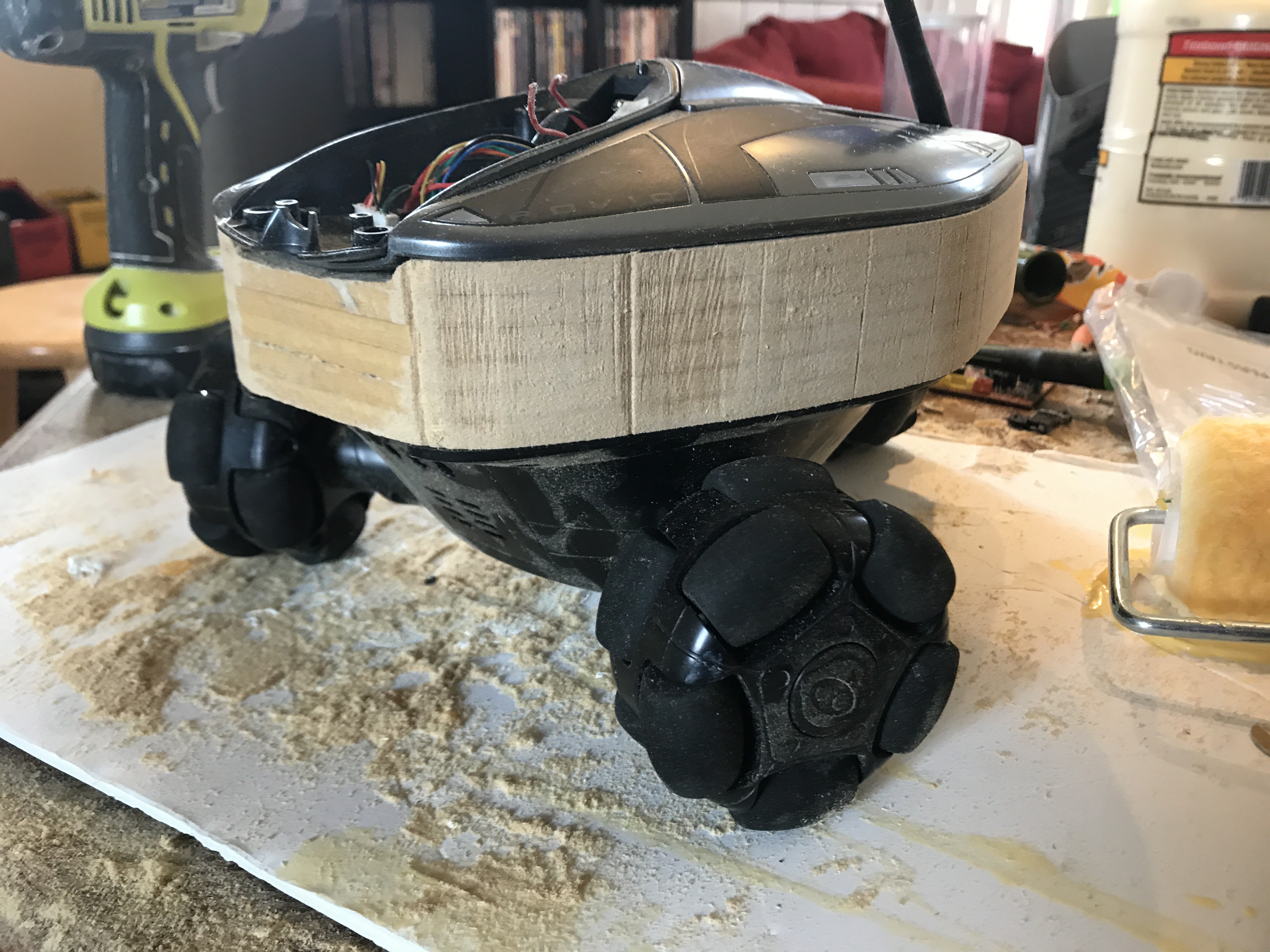
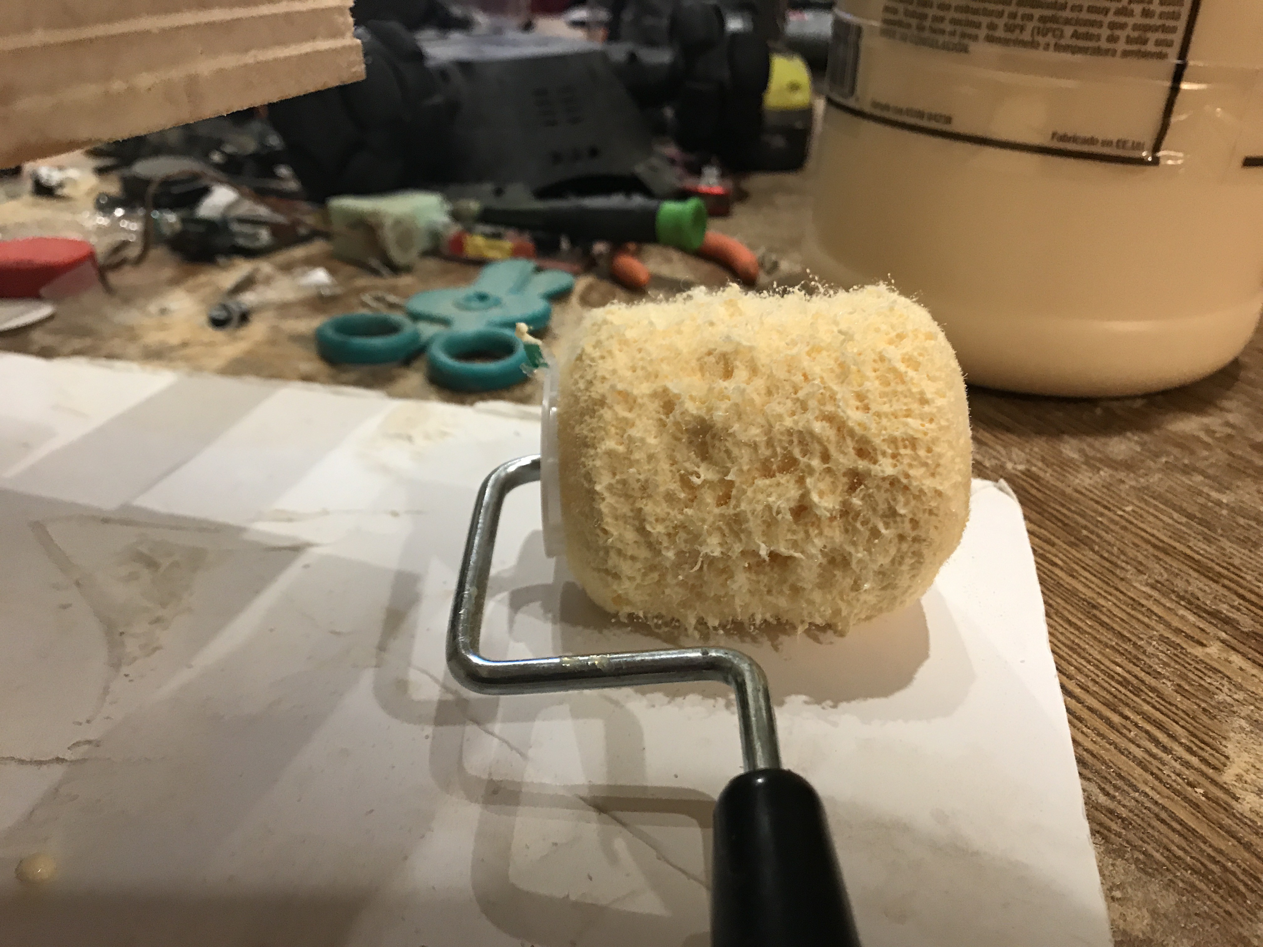
10/09/2018 at 13:38 • 0 commentsAfter two coats of Tite Bond glue which is also generally known as PVA plastic, you can see the wood has absorbed the PVA and also left a candy shell, with a light sand this is a paintable plastic finish. Next I need to decide where I want sensors or lights for example, or if I want to just leave is plain.
![]()
![]()
![]()
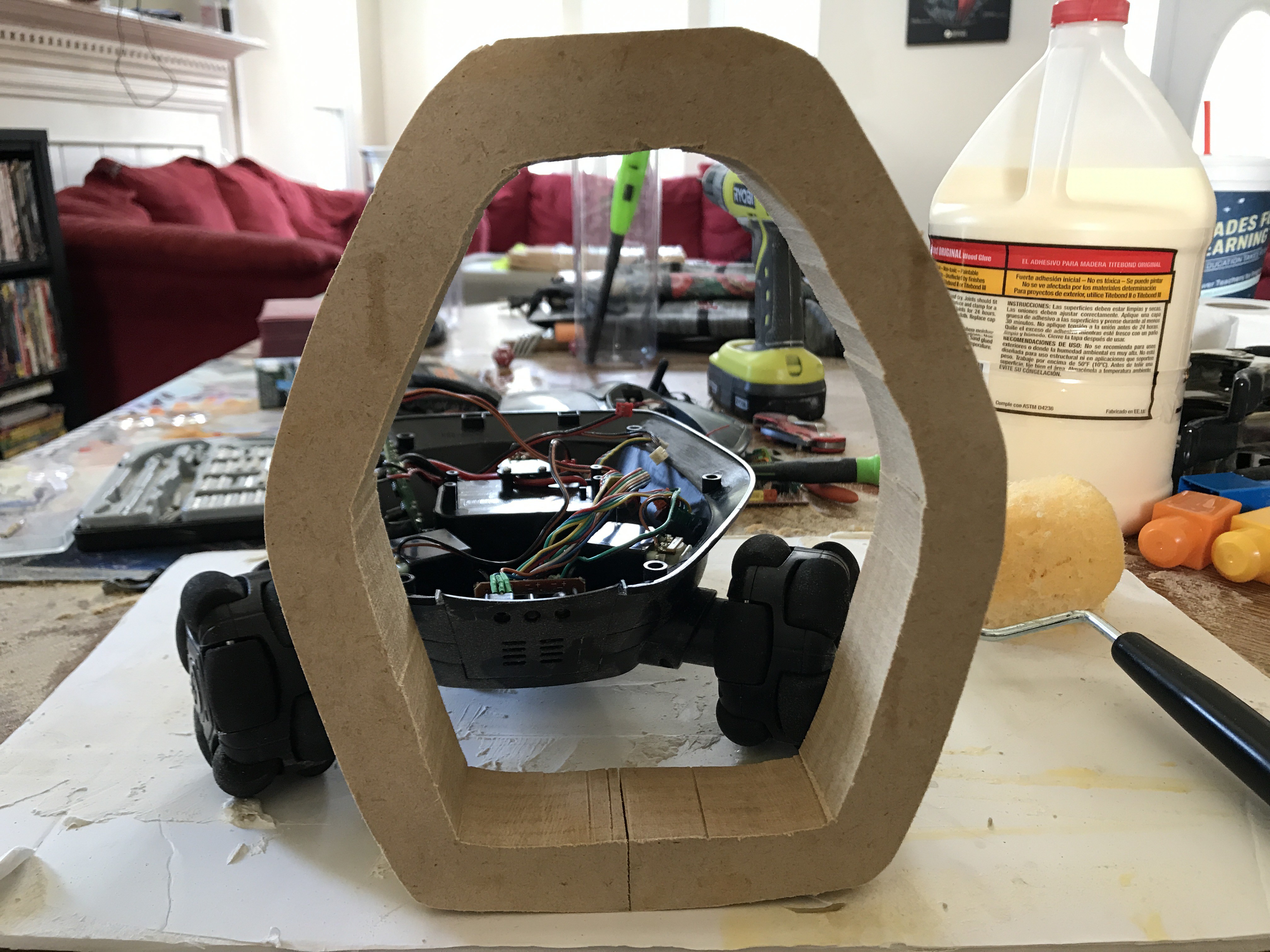
For some reason this last picture the whole body looks crooked but I believe that is because I free handed the trimming of the inside of the riser, and that makes it look weird, but the outside is within about 1 mm of the casing of the body all the way around.
-
Building space in the Rovio
10/09/2018 at 01:32 • 0 comments![]()
![]()
![]()
![]()
![]()
![]()
![]()
![]()
![]()
![]()
![]()
![]()
![]()
![]()
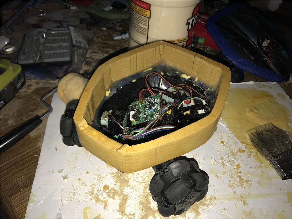
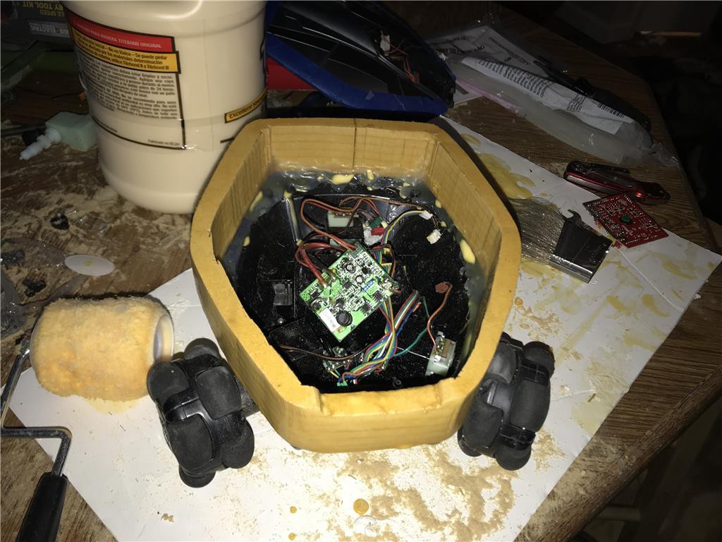
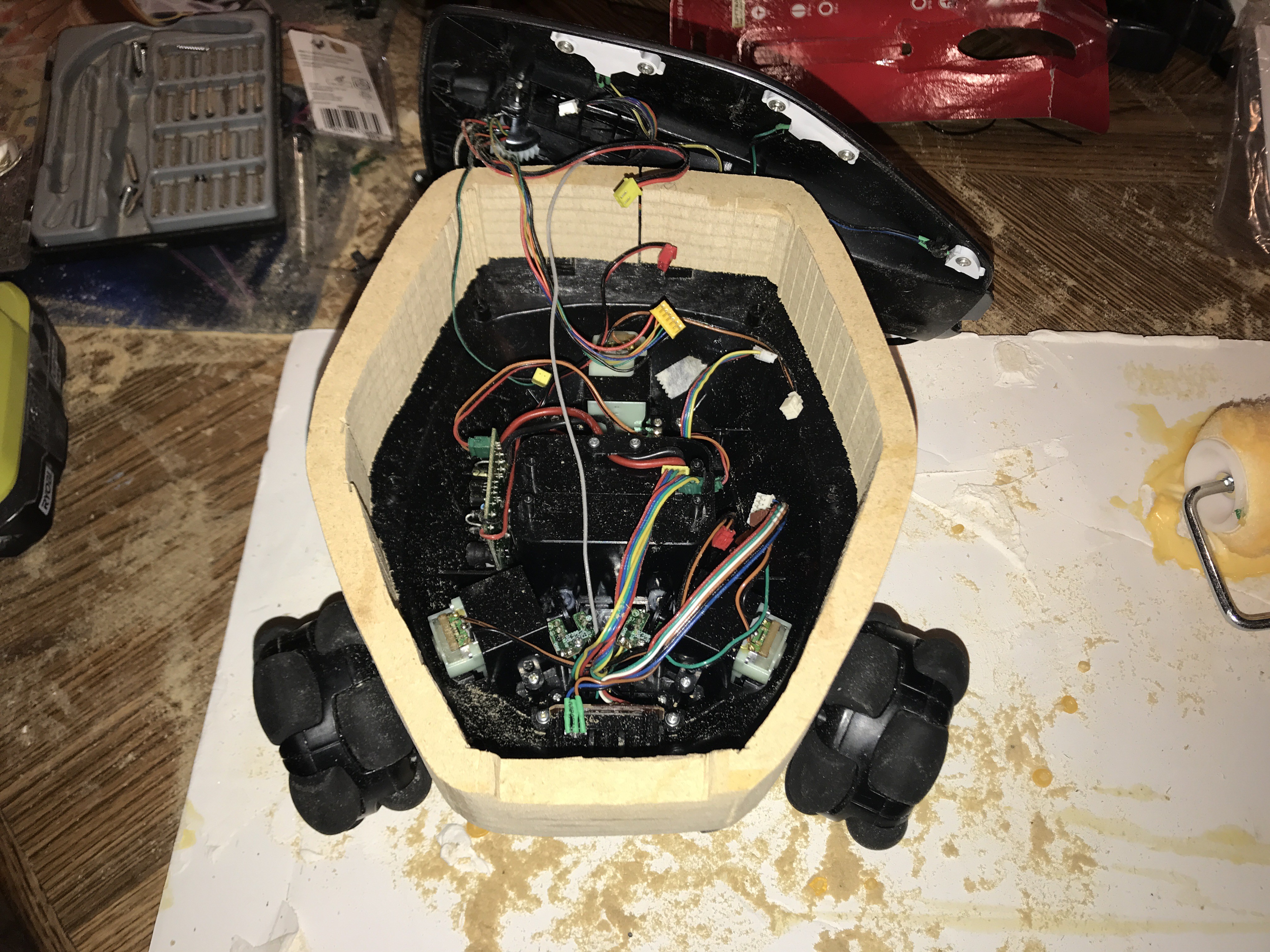
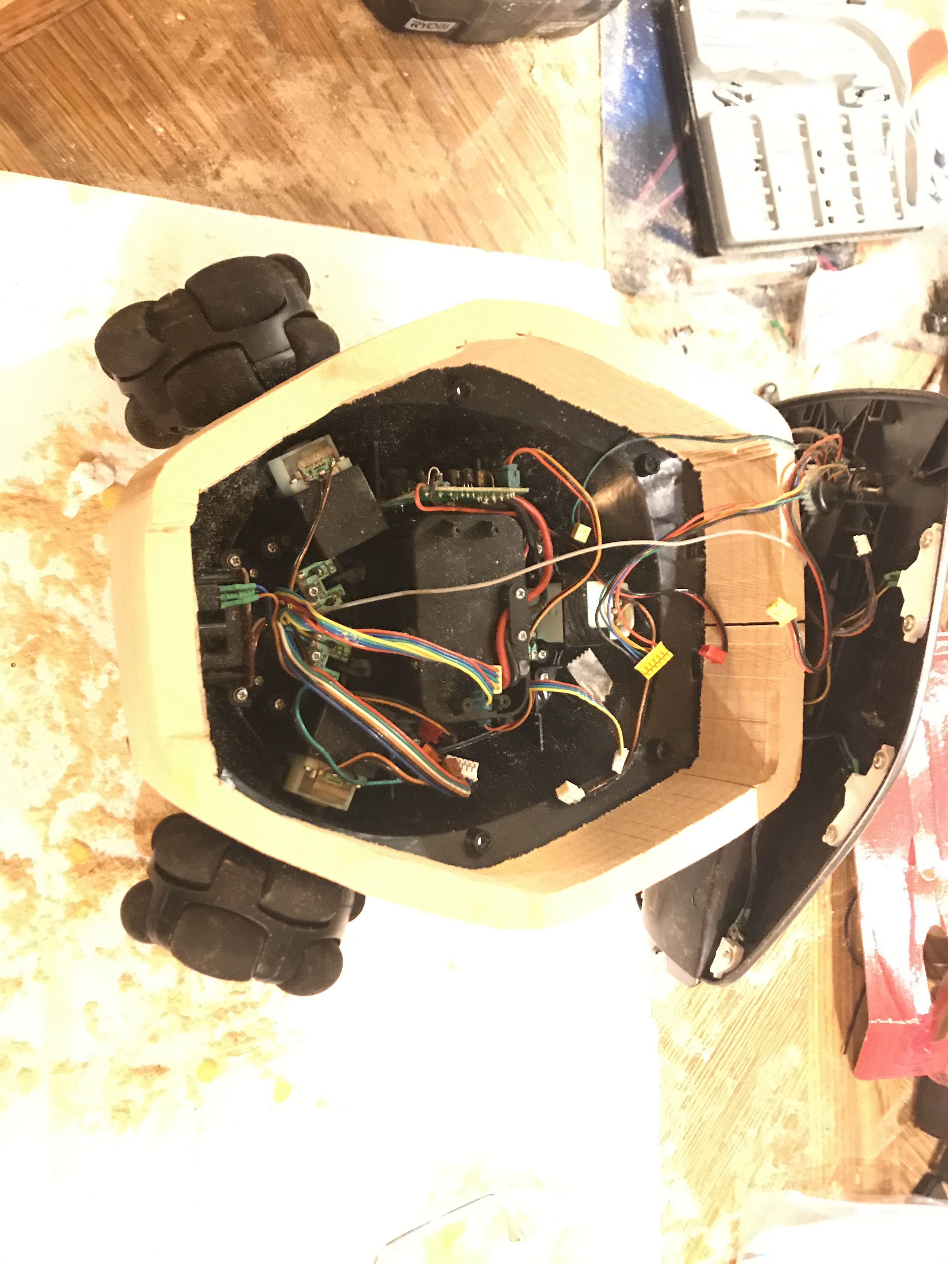
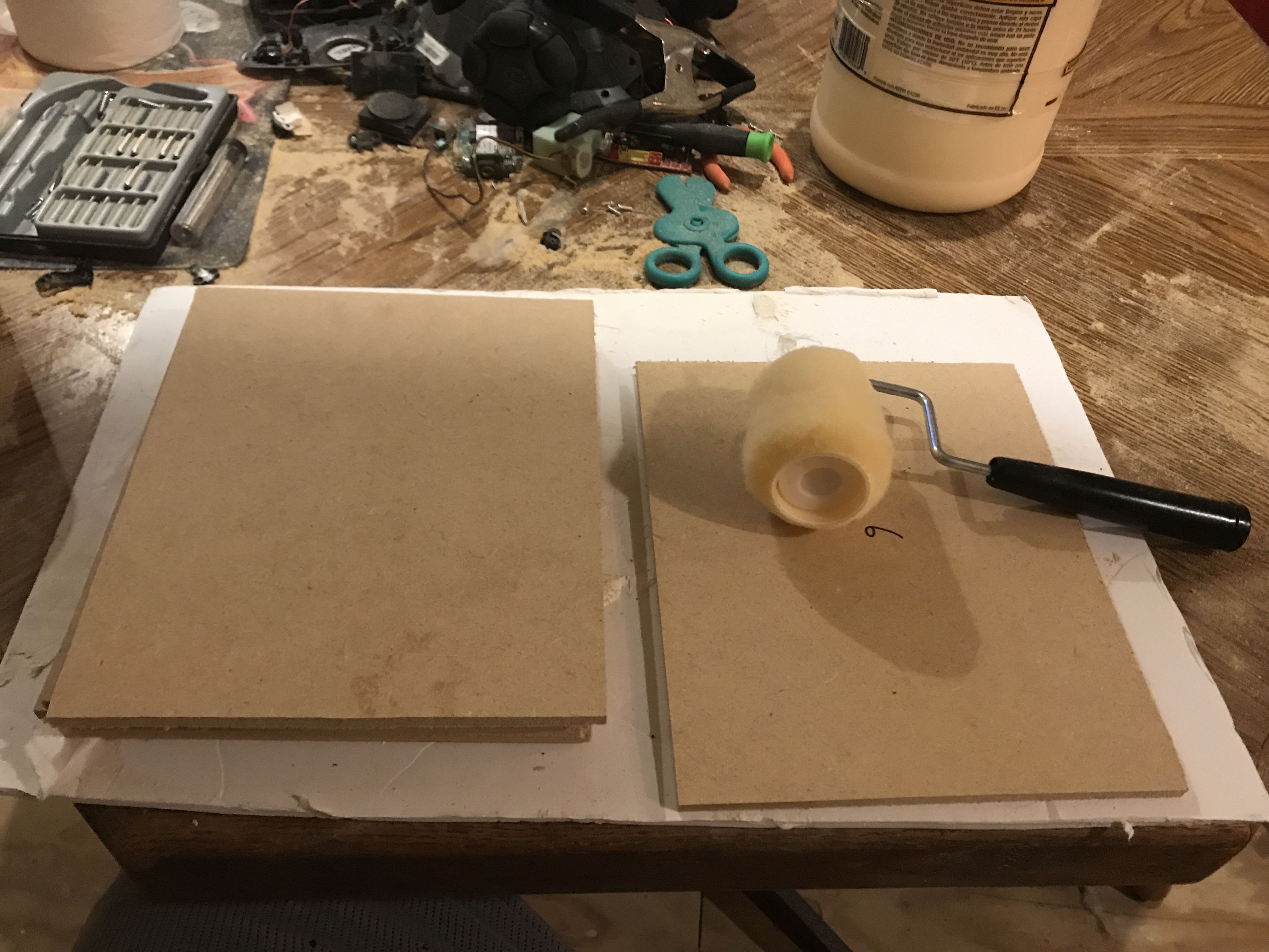
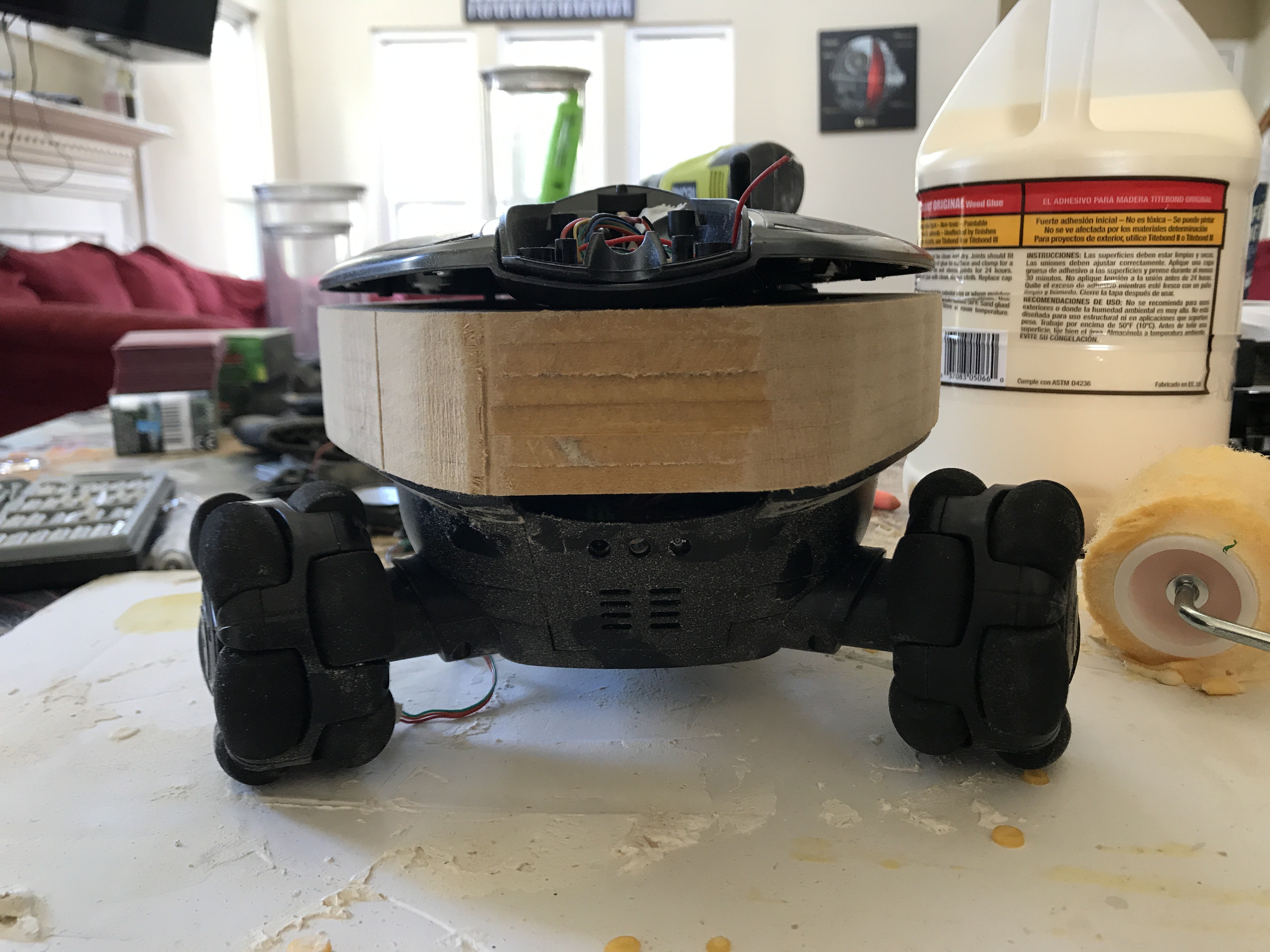
the Rovio is very tight inside , but fortunately I found a clever way to triple the internal space for the added equipment. I used thin sheets of mdf , glued and clamped them together to get the desired thickness. I traced the body of the Rovio onto the wood blank and cut to shape with a band saw.
-
Making the Rovio Thicker
10/08/2018 at 22:20 • 0 comments![]()
![]()
![]()
![]()
![]()
![]()
![]()
![]()
![]()
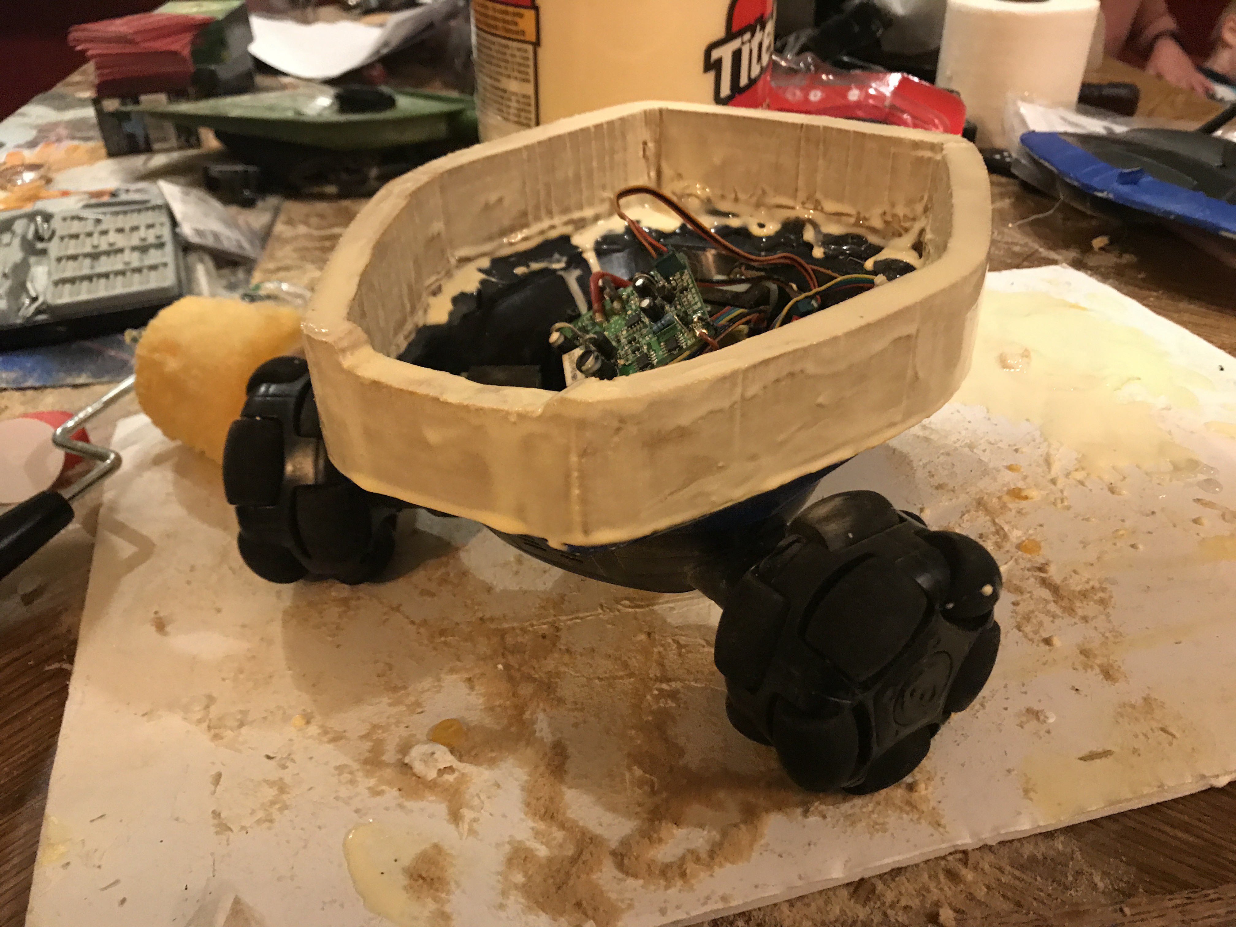
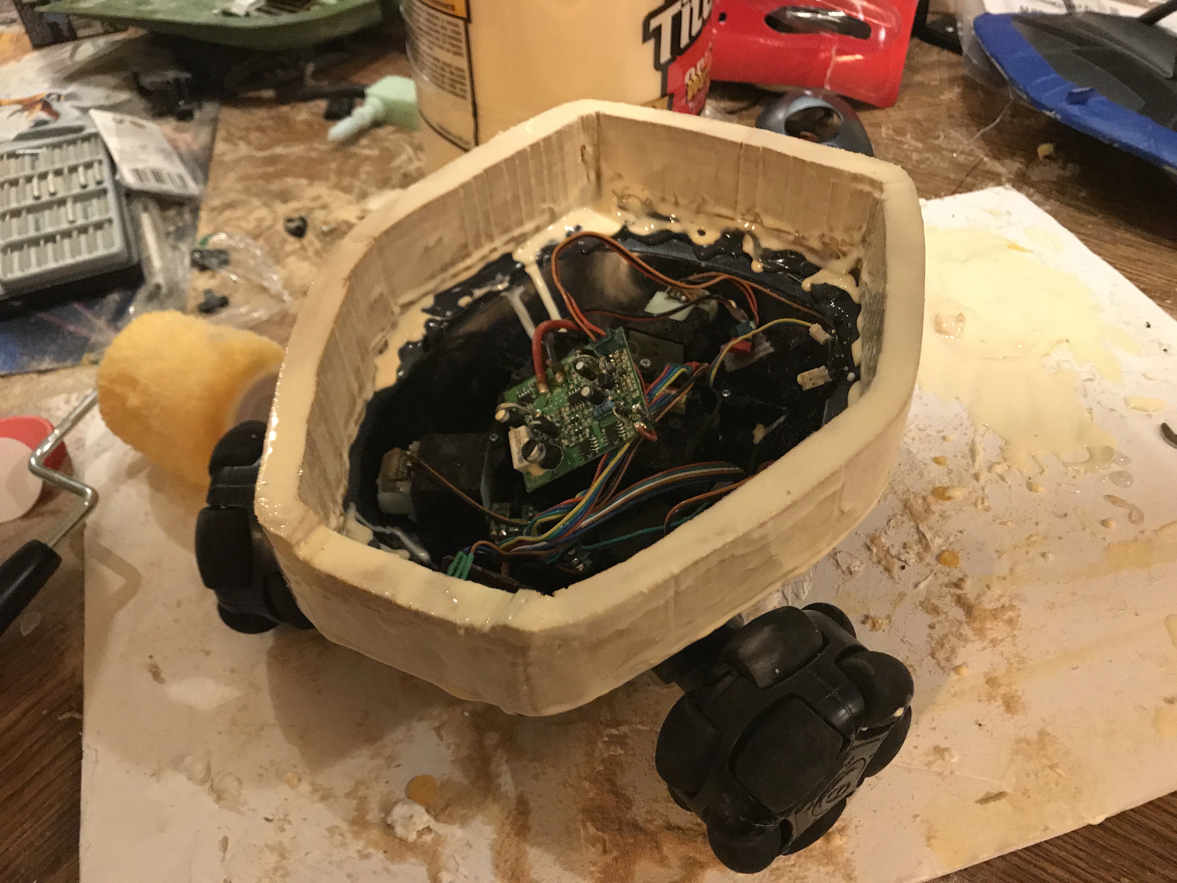
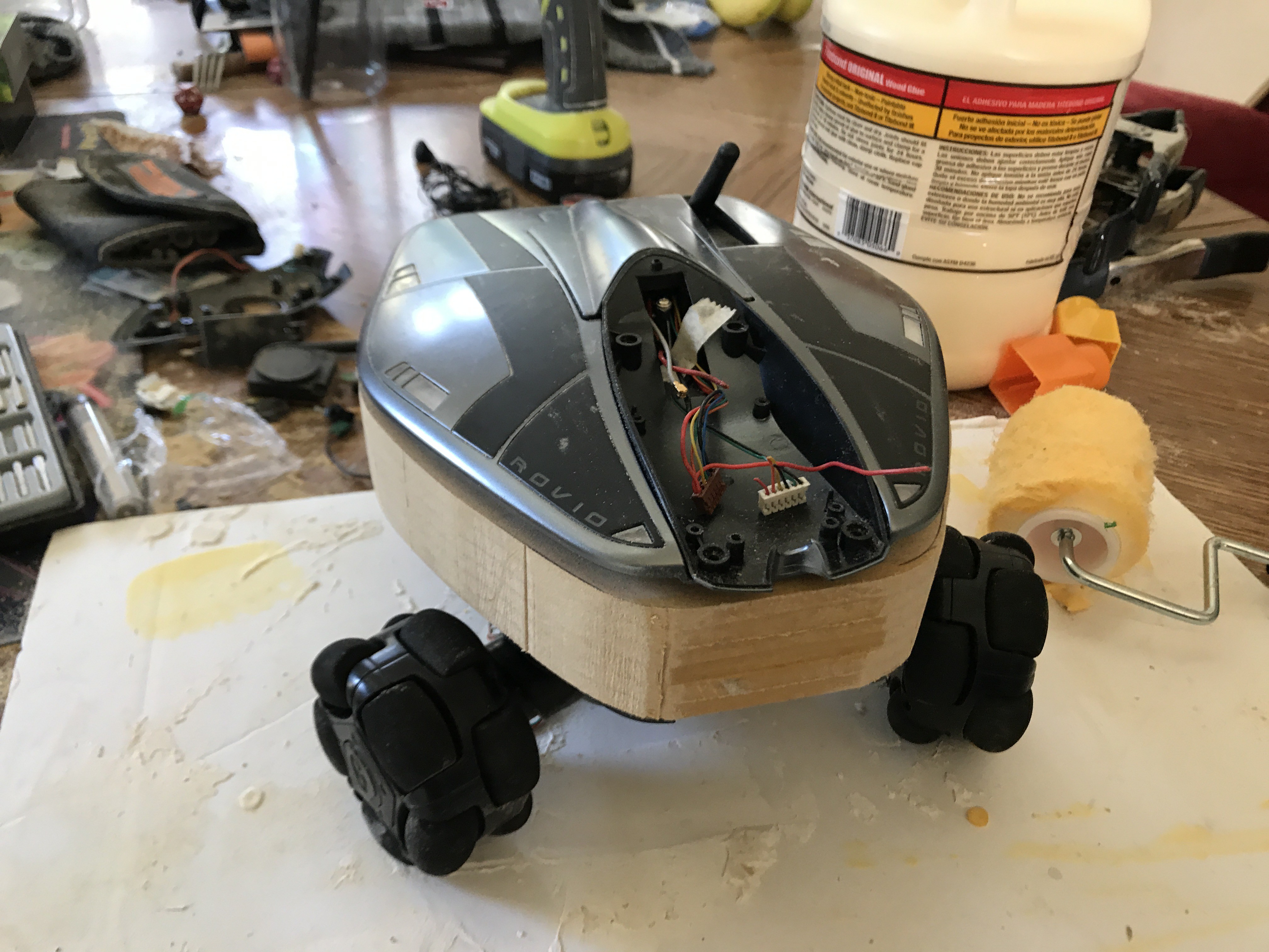
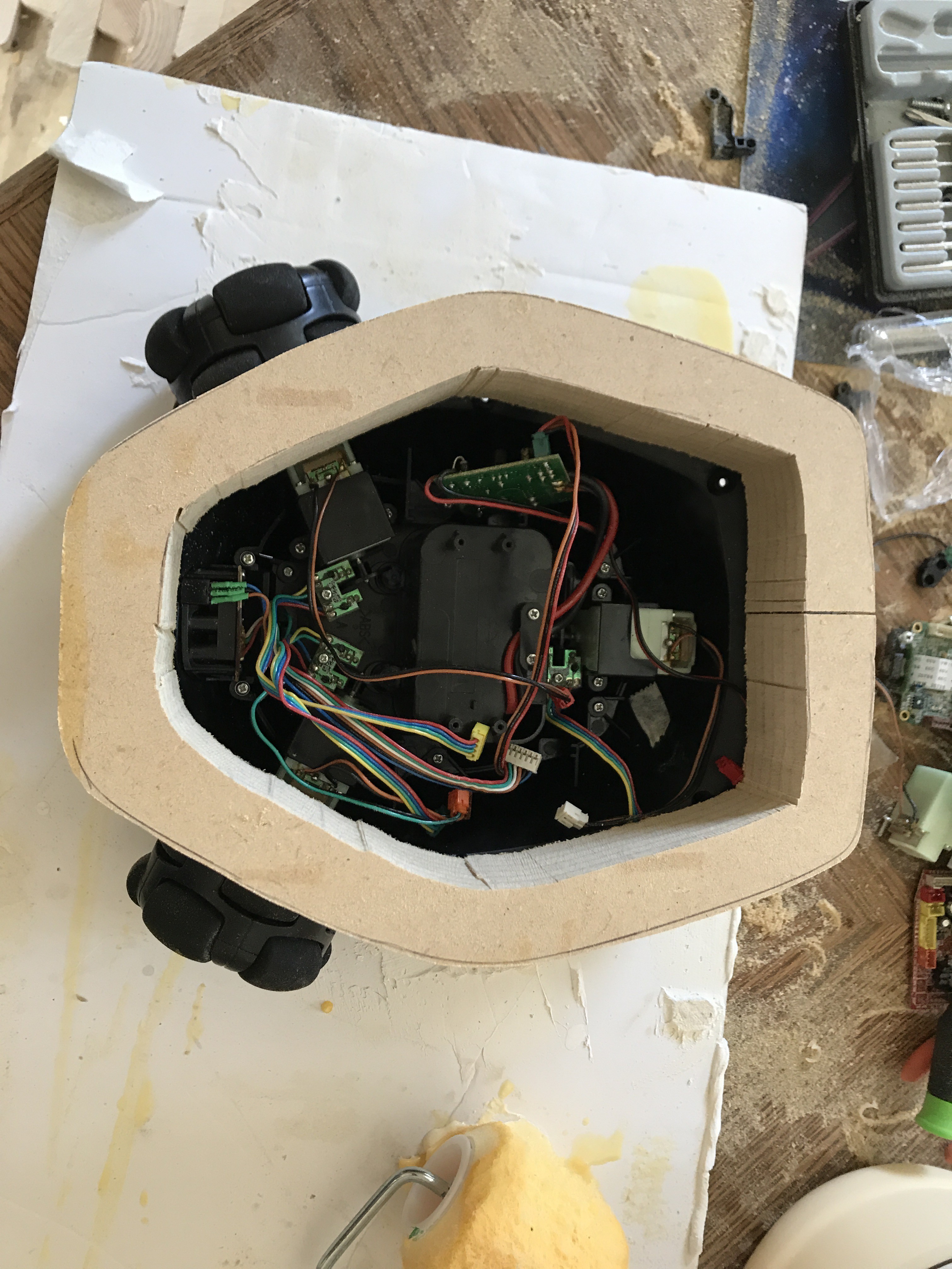
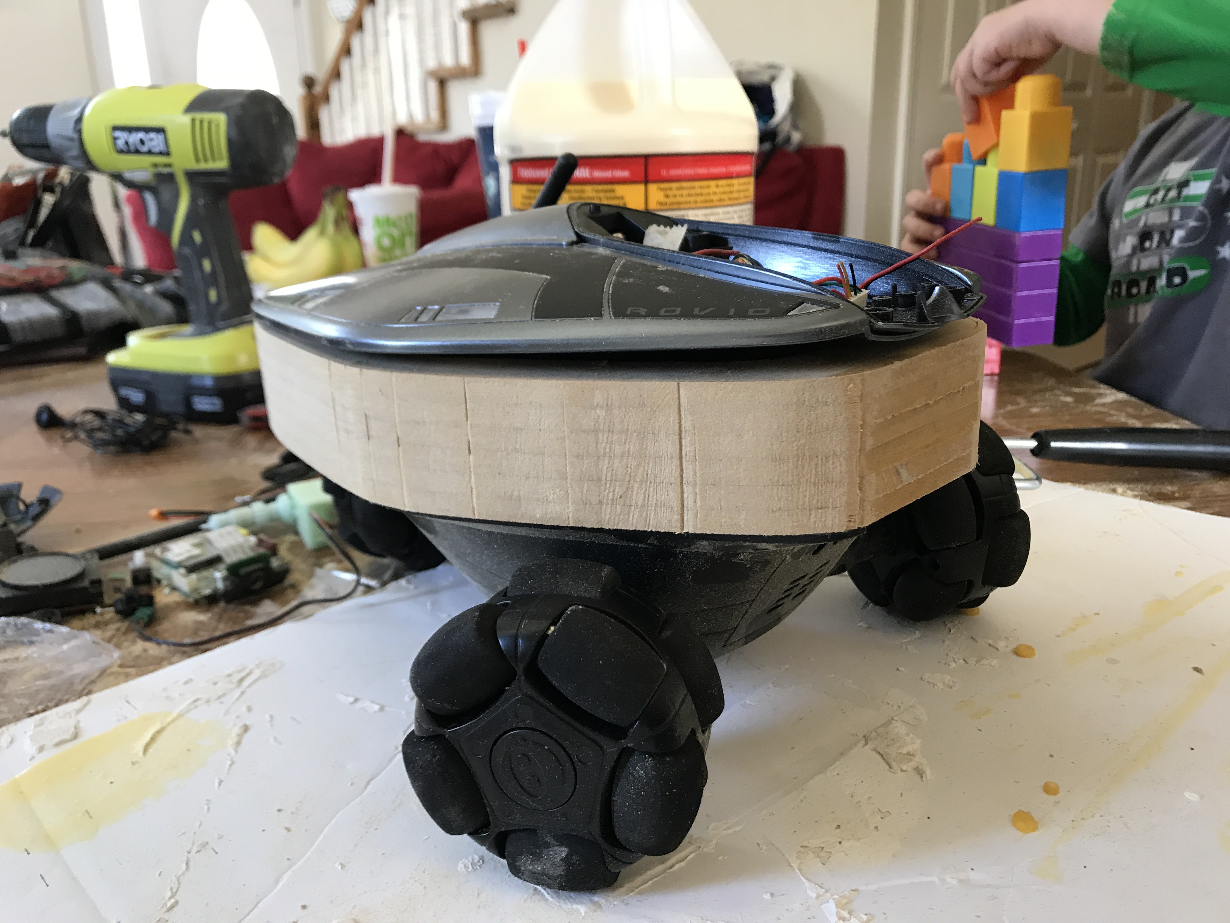
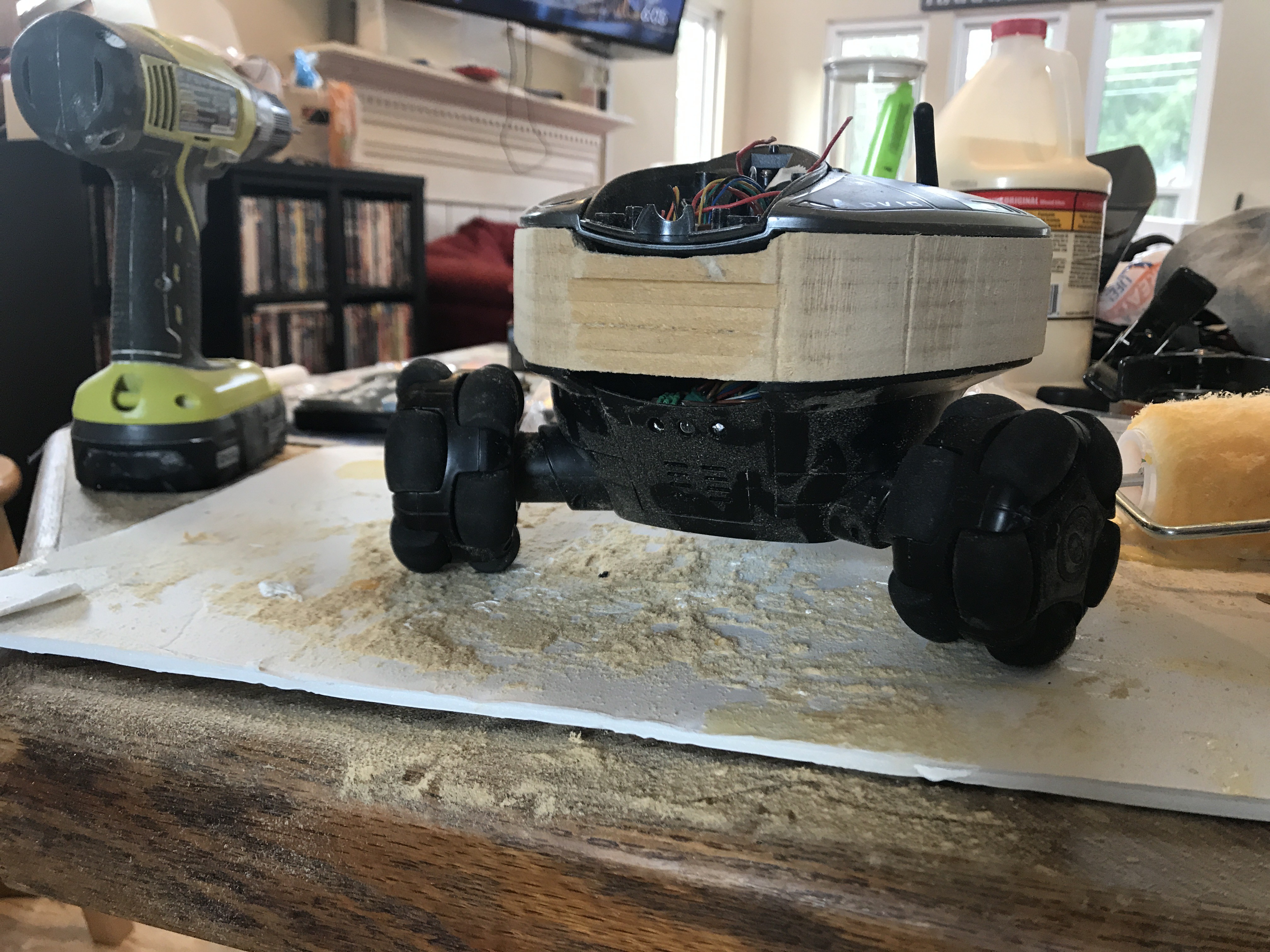
HUpdate, inside the Rovio is very tight so I am modding the body to accept a spacer 1.5 inches thick to make room for modern electronics. Laminated mdf carved until the top fits smoothly in. once it is sealed and texture sprayed black it will look like it was built that way! Stay tuned
-
Building the Rovio 2.0
10/08/2018 at 04:46 • 0 comments![]()
![]()
![]()
![]()
![]()
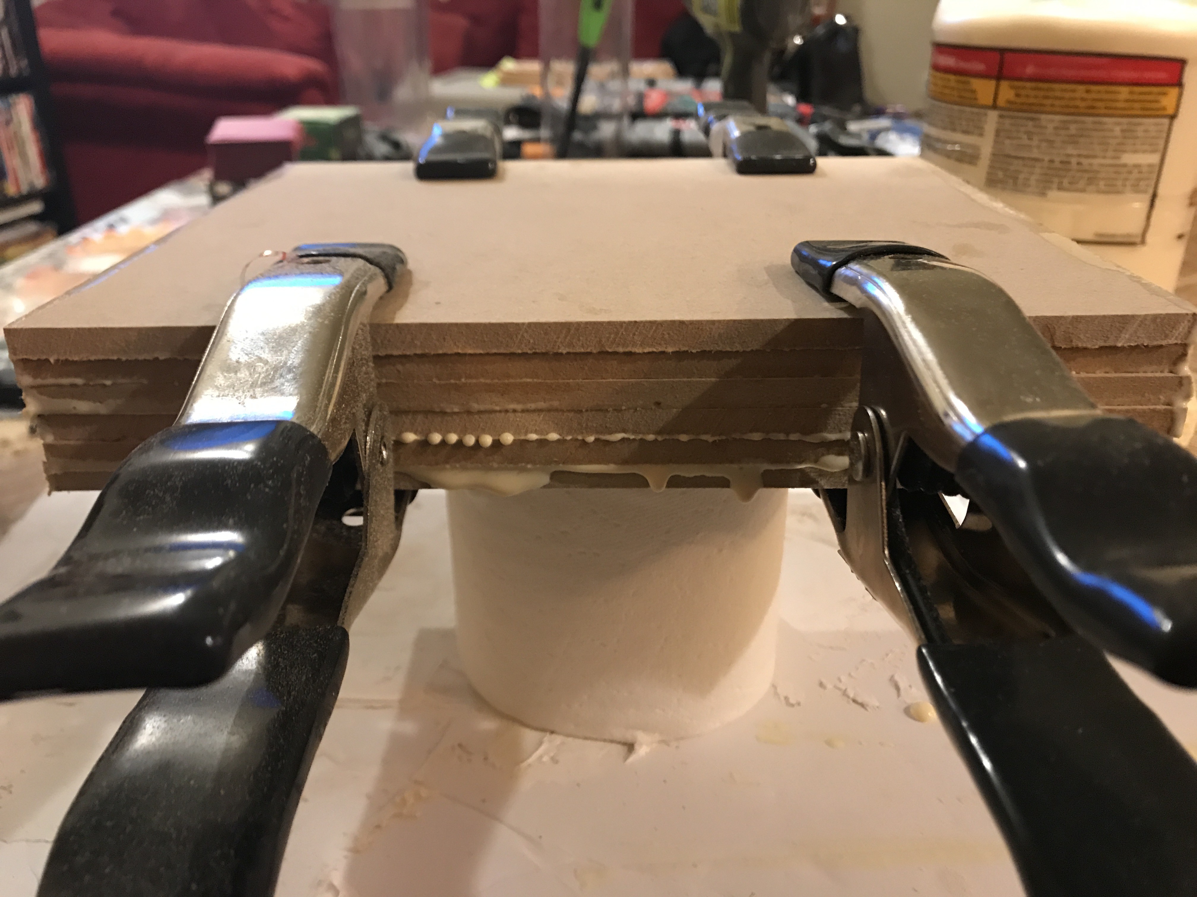
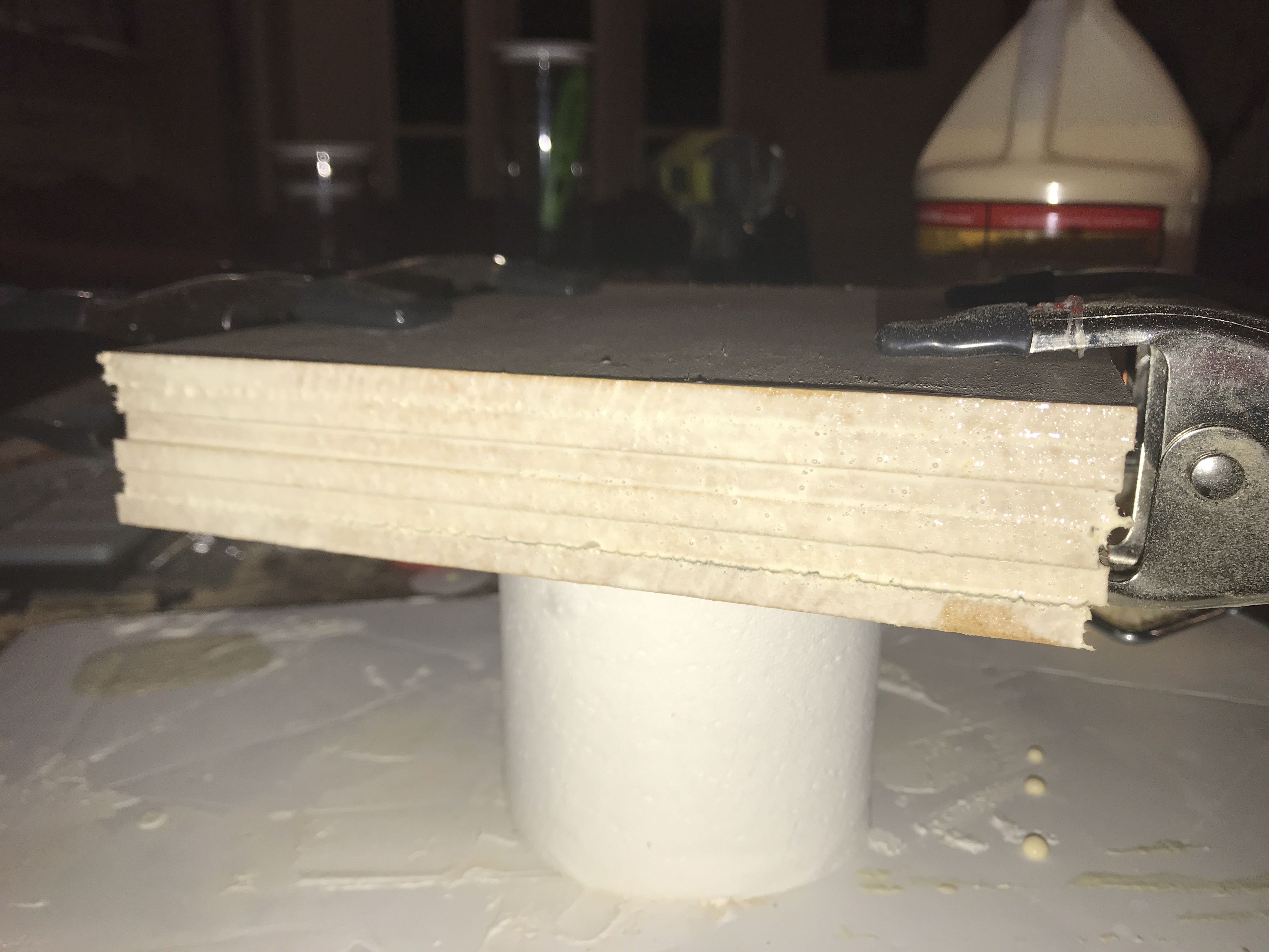
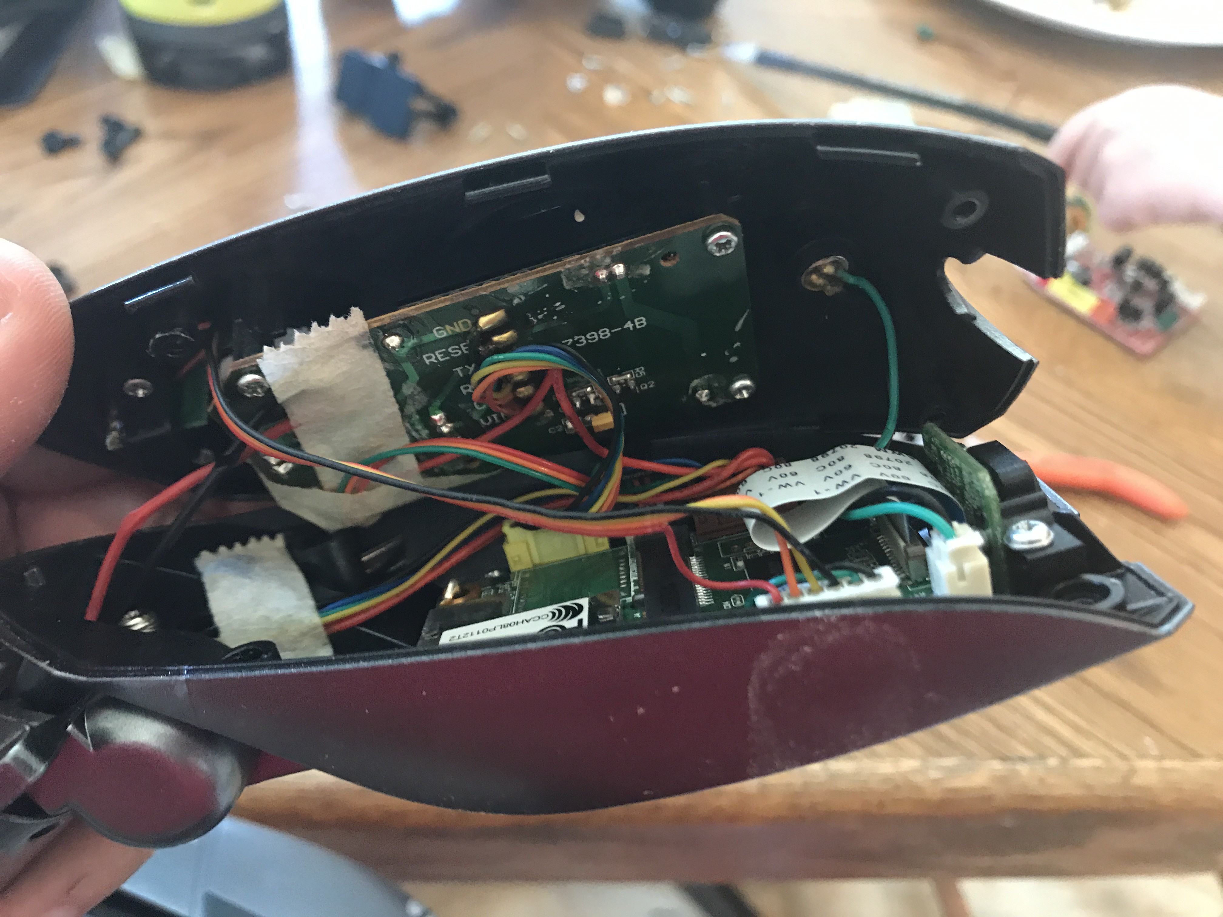
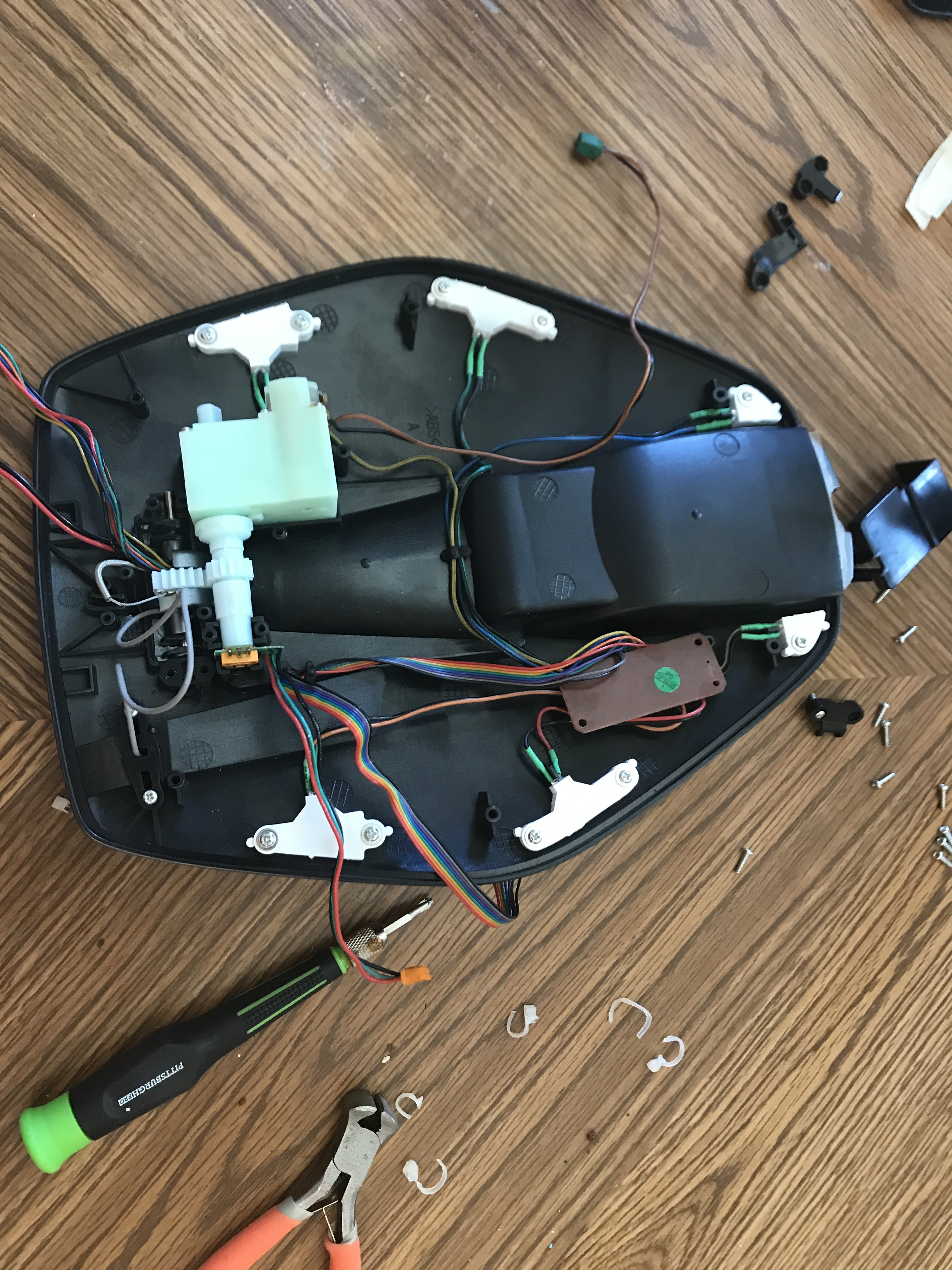
The first thing you notice when tearing down the Rovio is how tight all the electronics fit in. Unlike most consumer based electronics there isn’t much room for third party additions. I made the executive decision to make a riser between the lower and top body. This should give me room for controllers, h bridges, sensors and a bigger battery as well. I traced out the body onto quarter inch thick MDF sheet , cut out six slices to the same size and stacked them. Each layer has wood glue in between to bond them into one. The entire sandwich is compressed together with 4 large spring clamps while these dry overnight.
-
Practical Application on a Robot
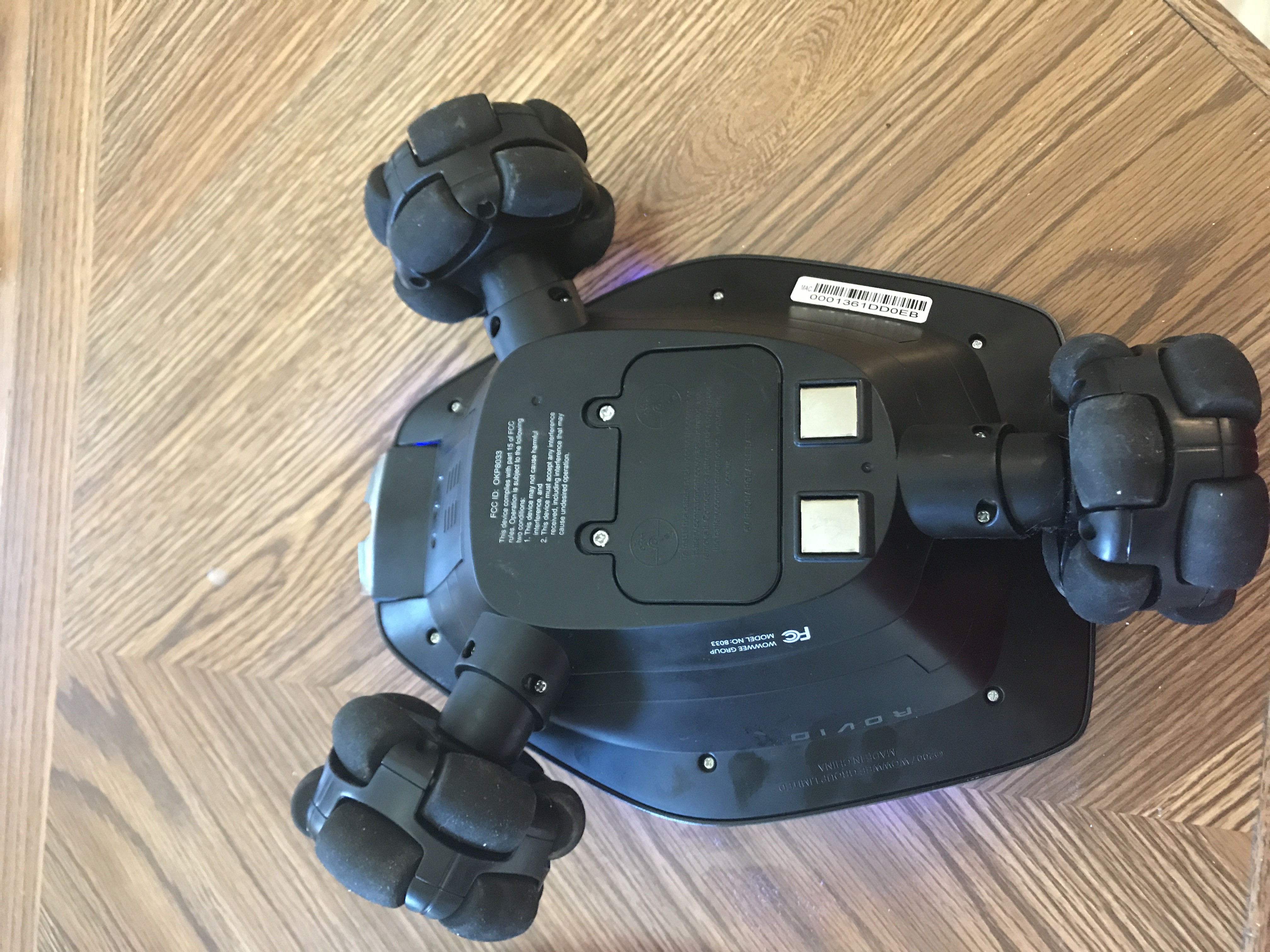
10/08/2018 at 04:39 • 0 commentshello all , here is a tiny update. In order to better demonstrate practical use of discrete QR code navigation I need to incorporate the sensors onto a live robot. Initially I was going with a mini turtle style platform , but I simply do not think it gives this Hackaday competition justice using a cheap dinky platform. So in true Hackaday fashion we need to void some warranties!! I have some donors available and I believe the Wowwee Rovio could be a good fit for teardown and rebuild with modern electronics and the Invisible QR code tracking system. I will implement both bottom , forward, and top reading for general use. I am tinkering around with the idea of a rear facing camera for docking purposes.
-
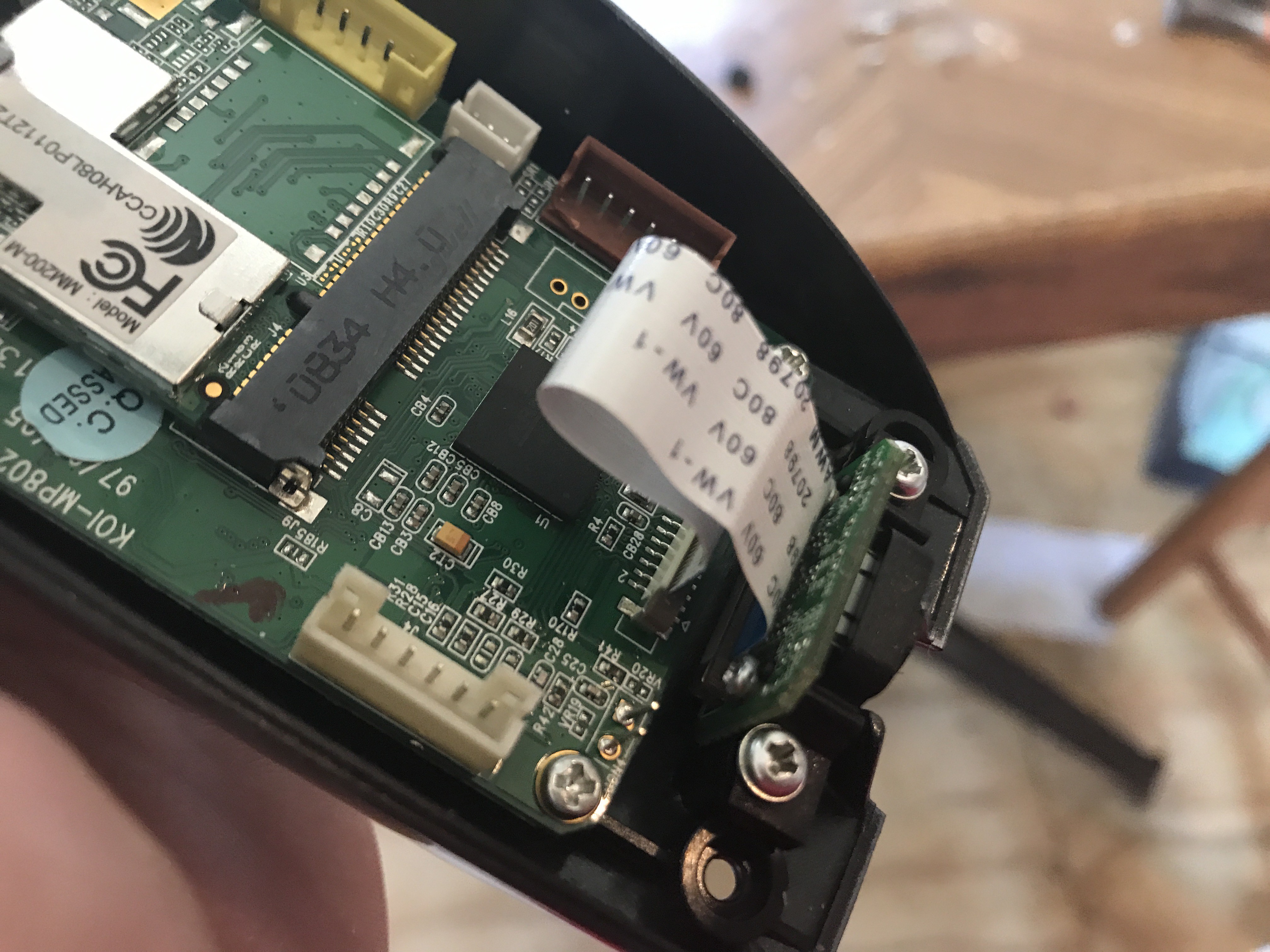
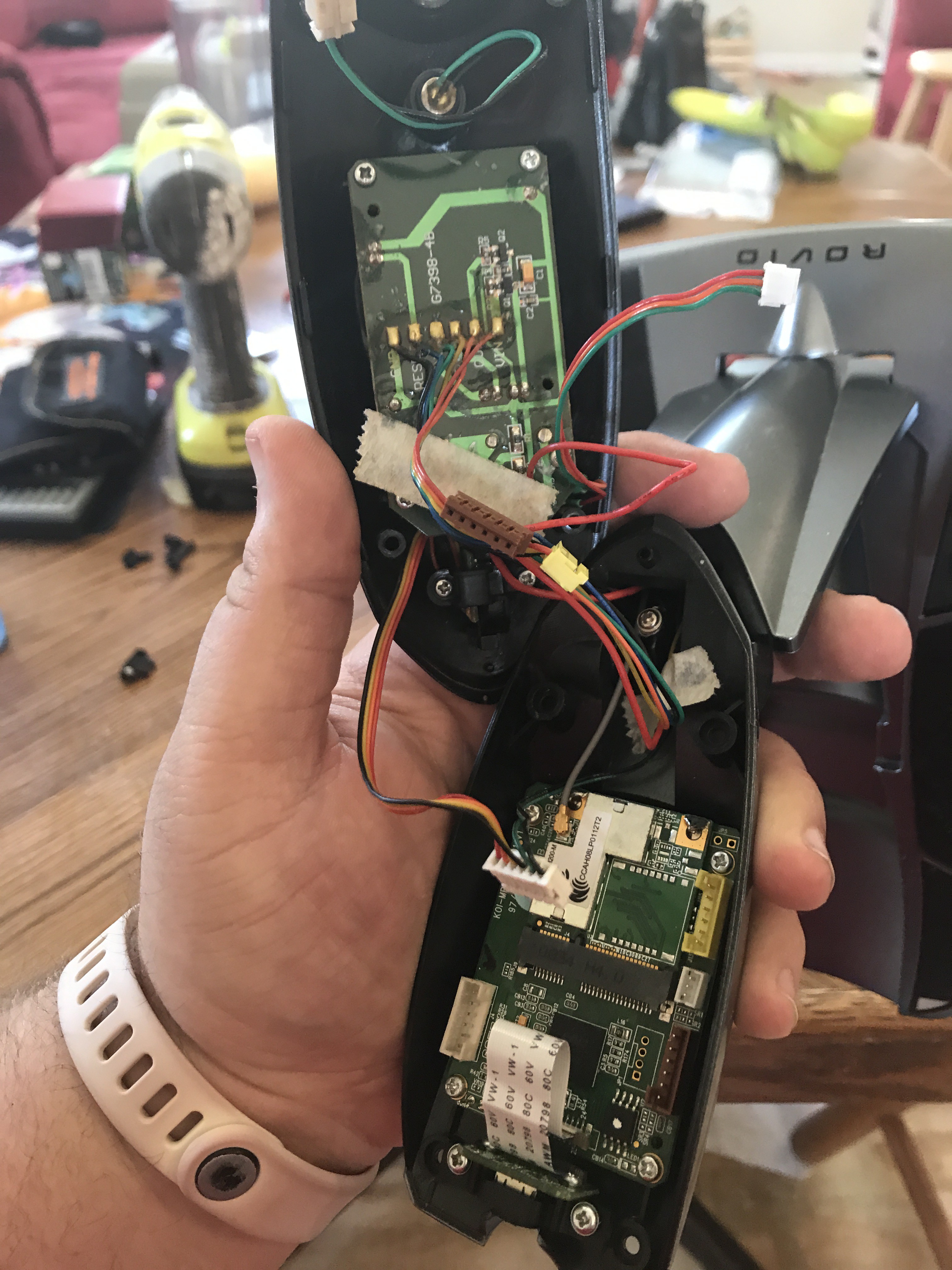
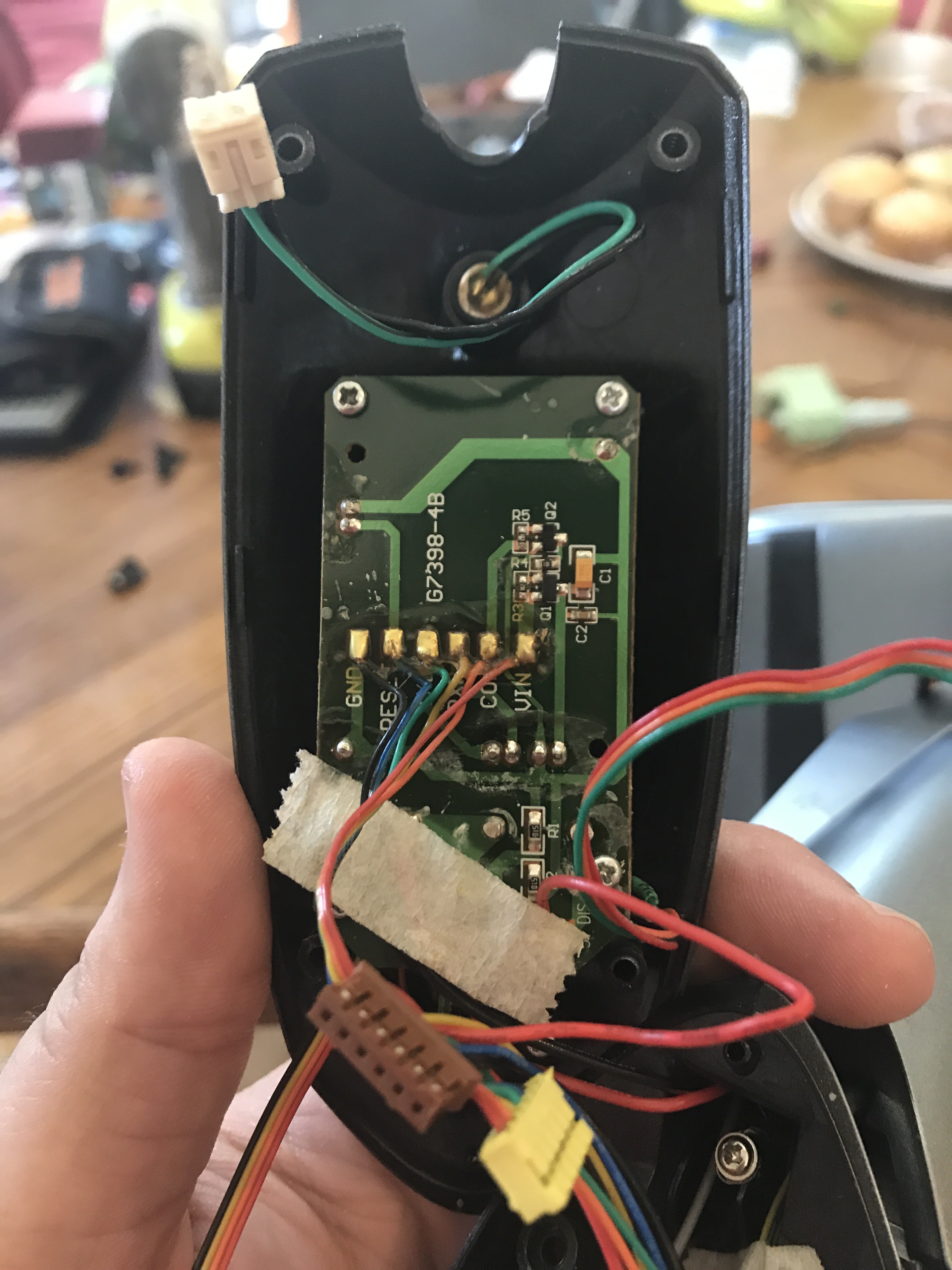
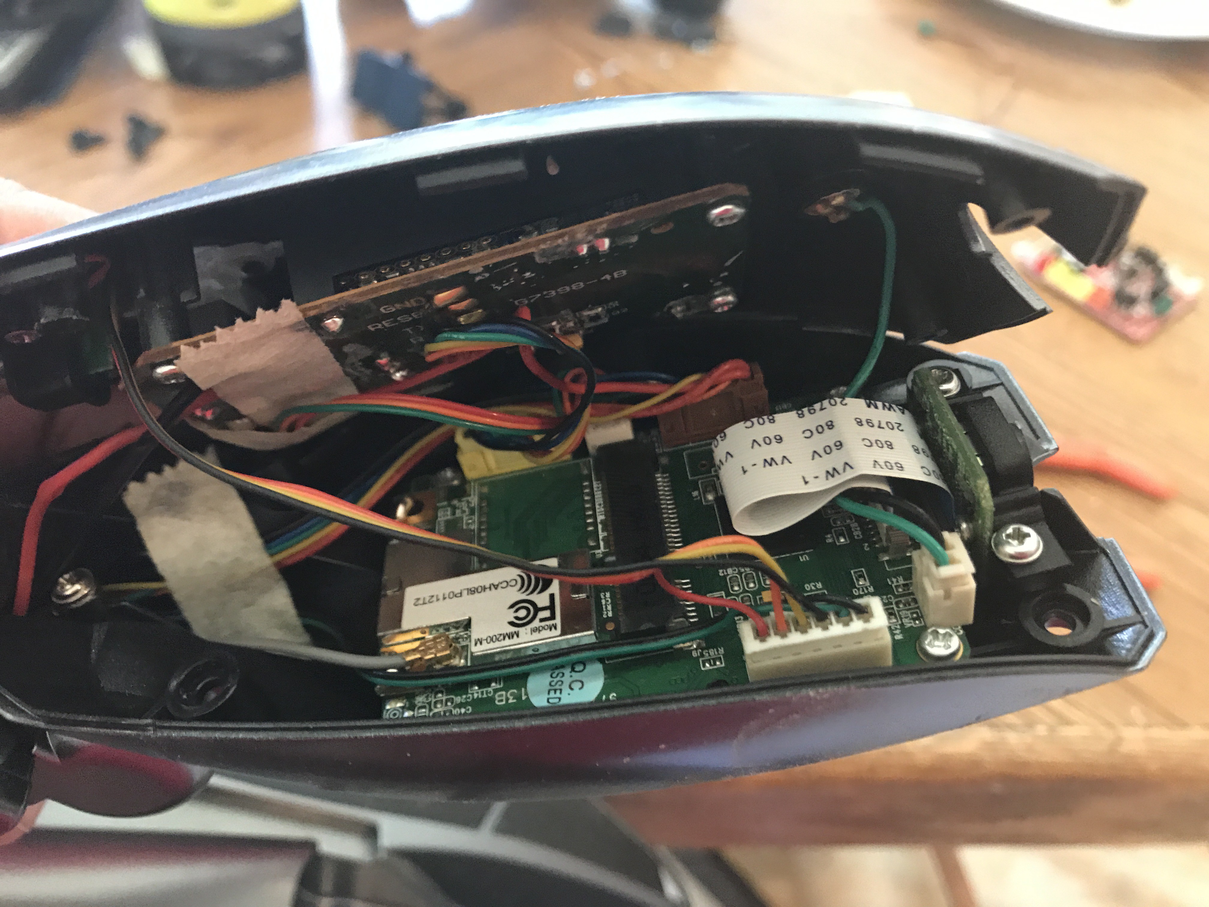
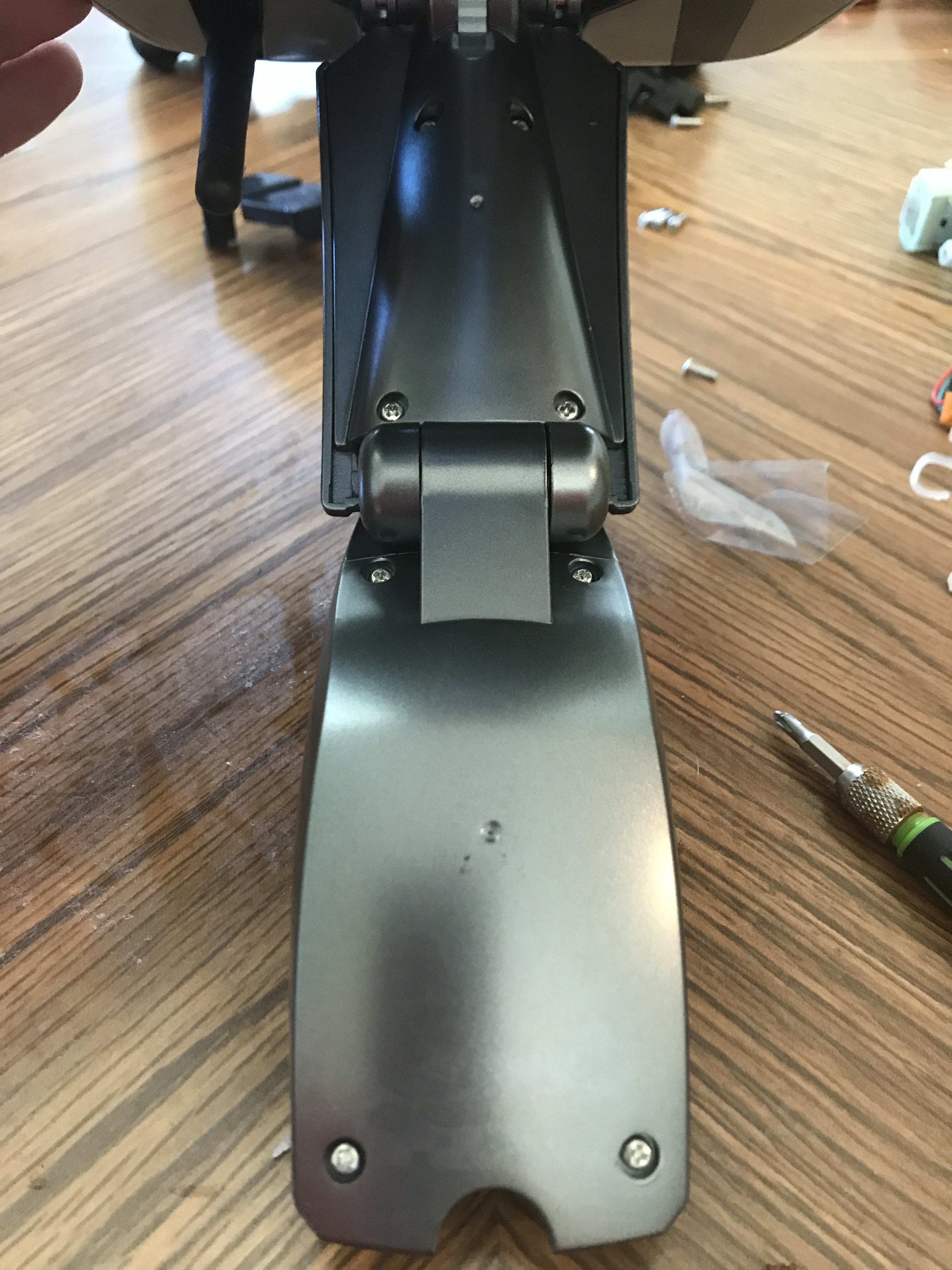
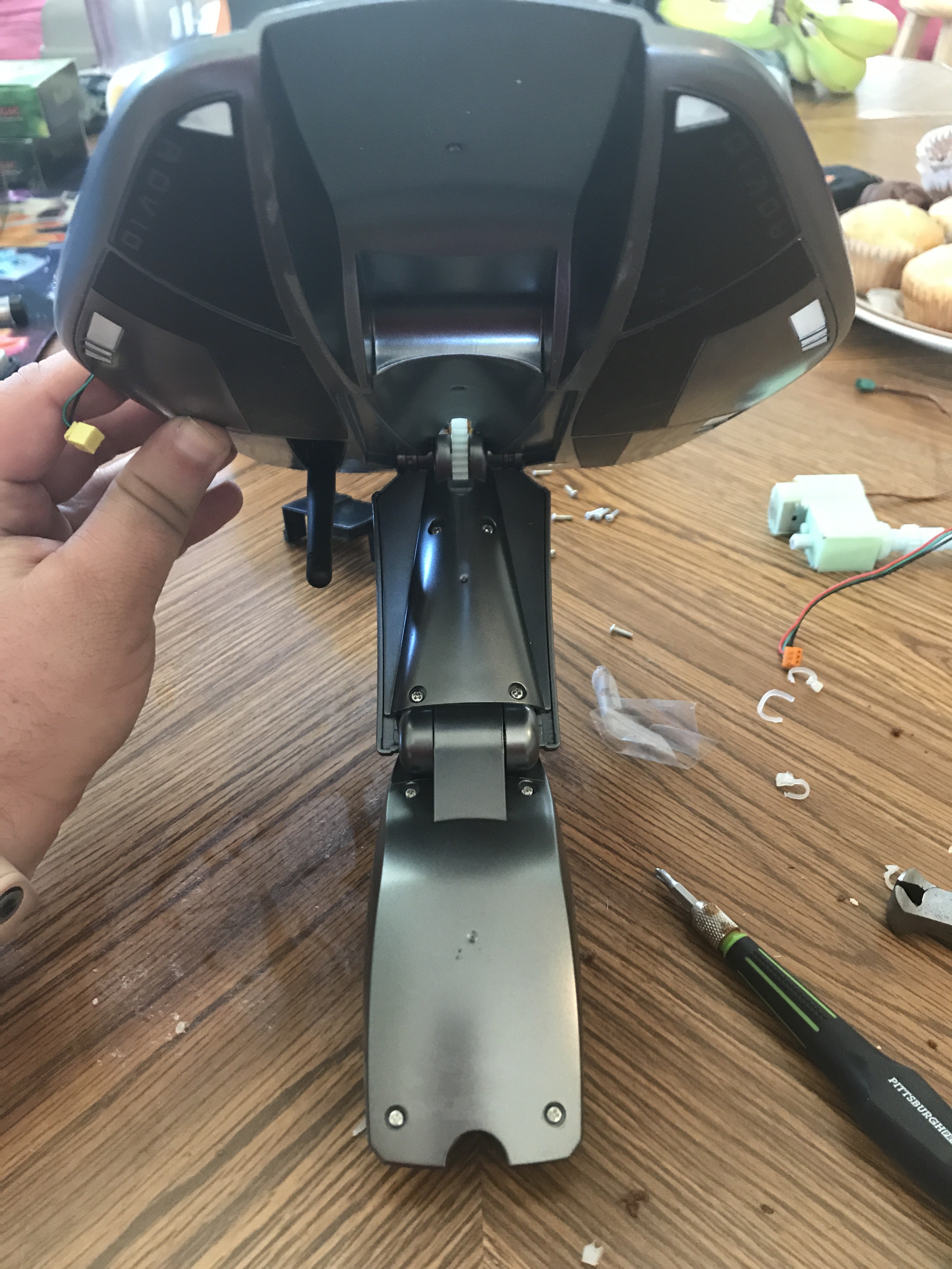
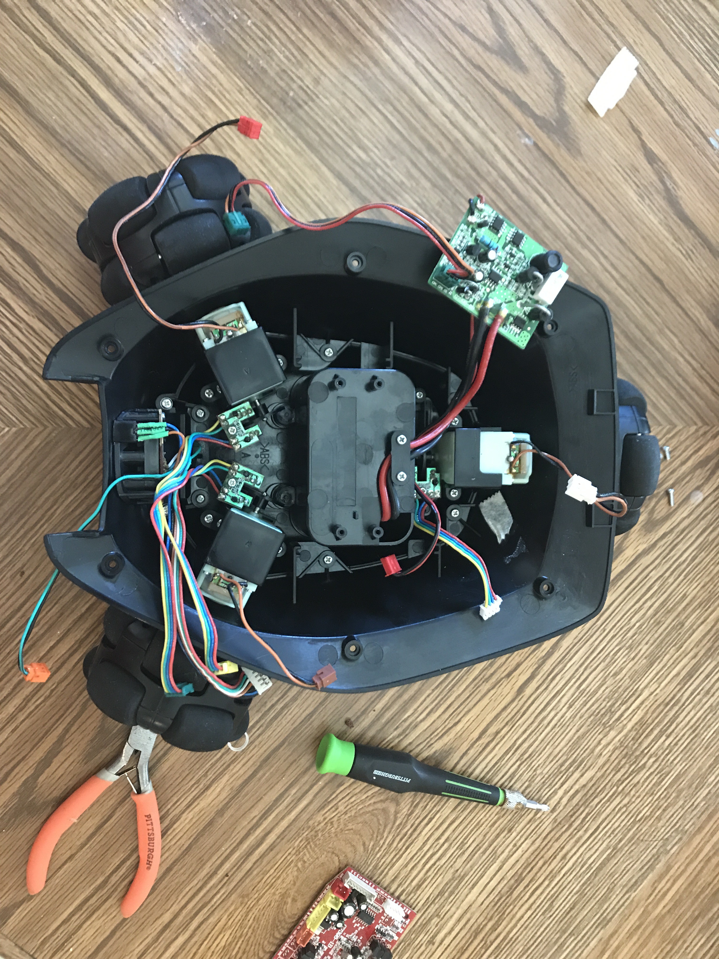
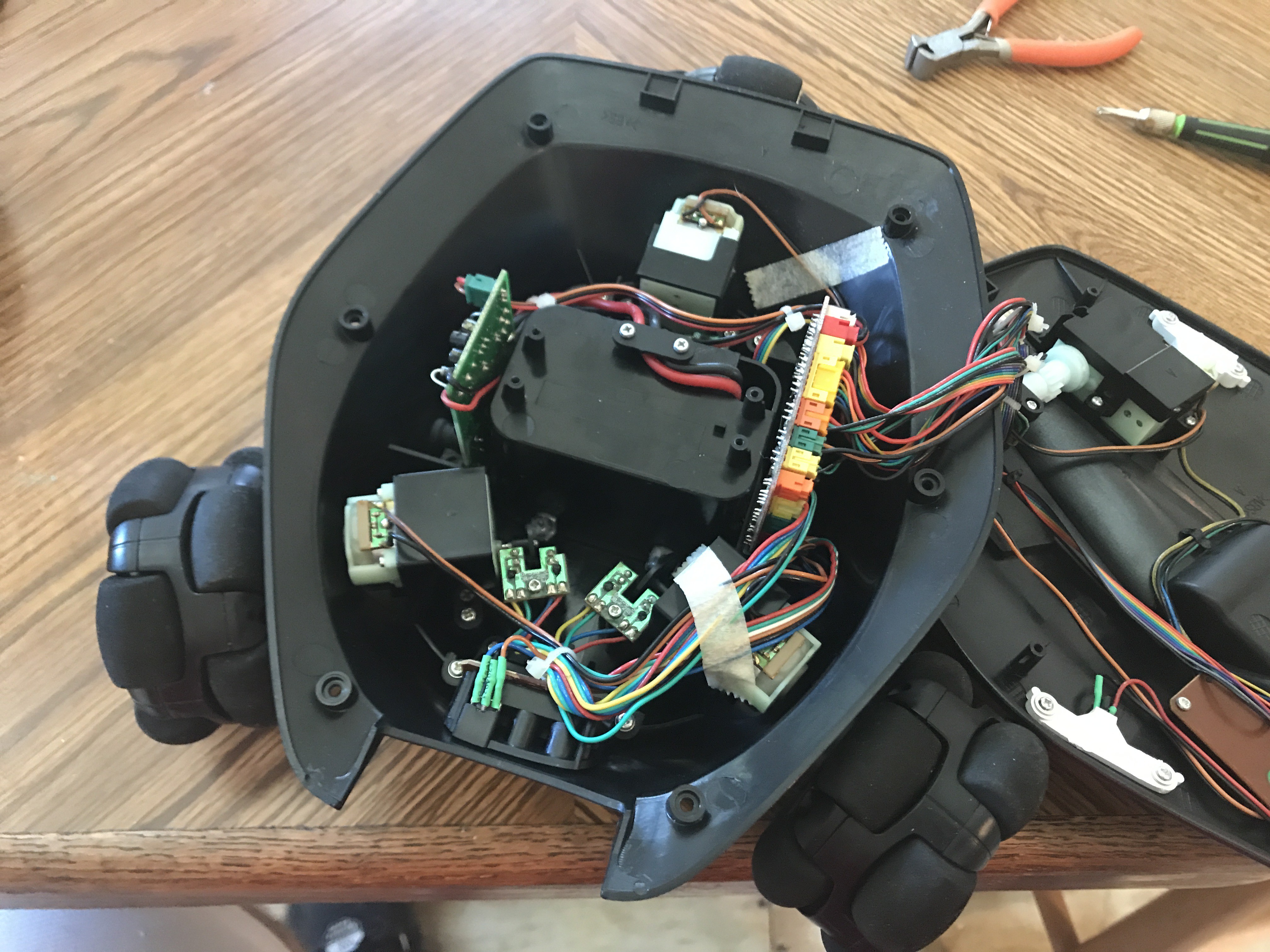
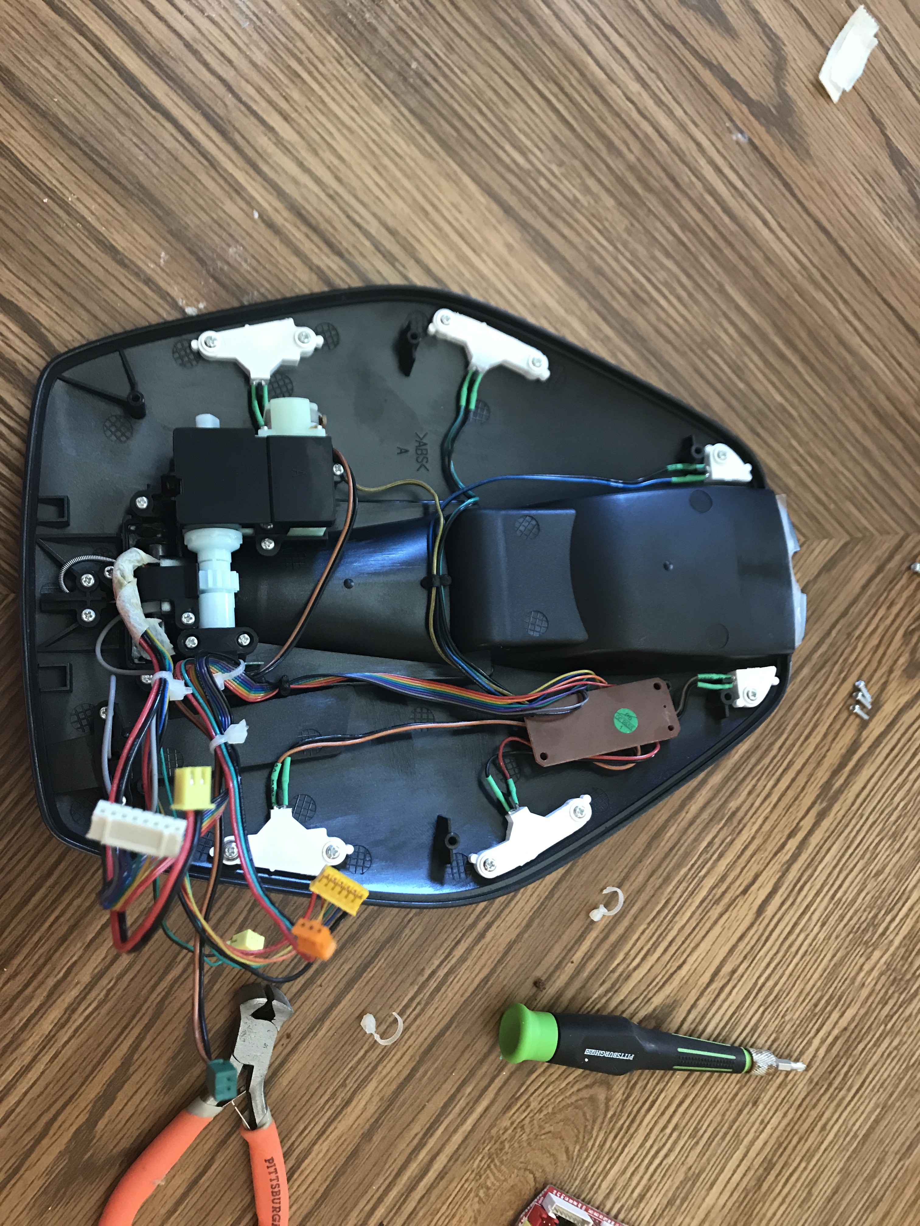
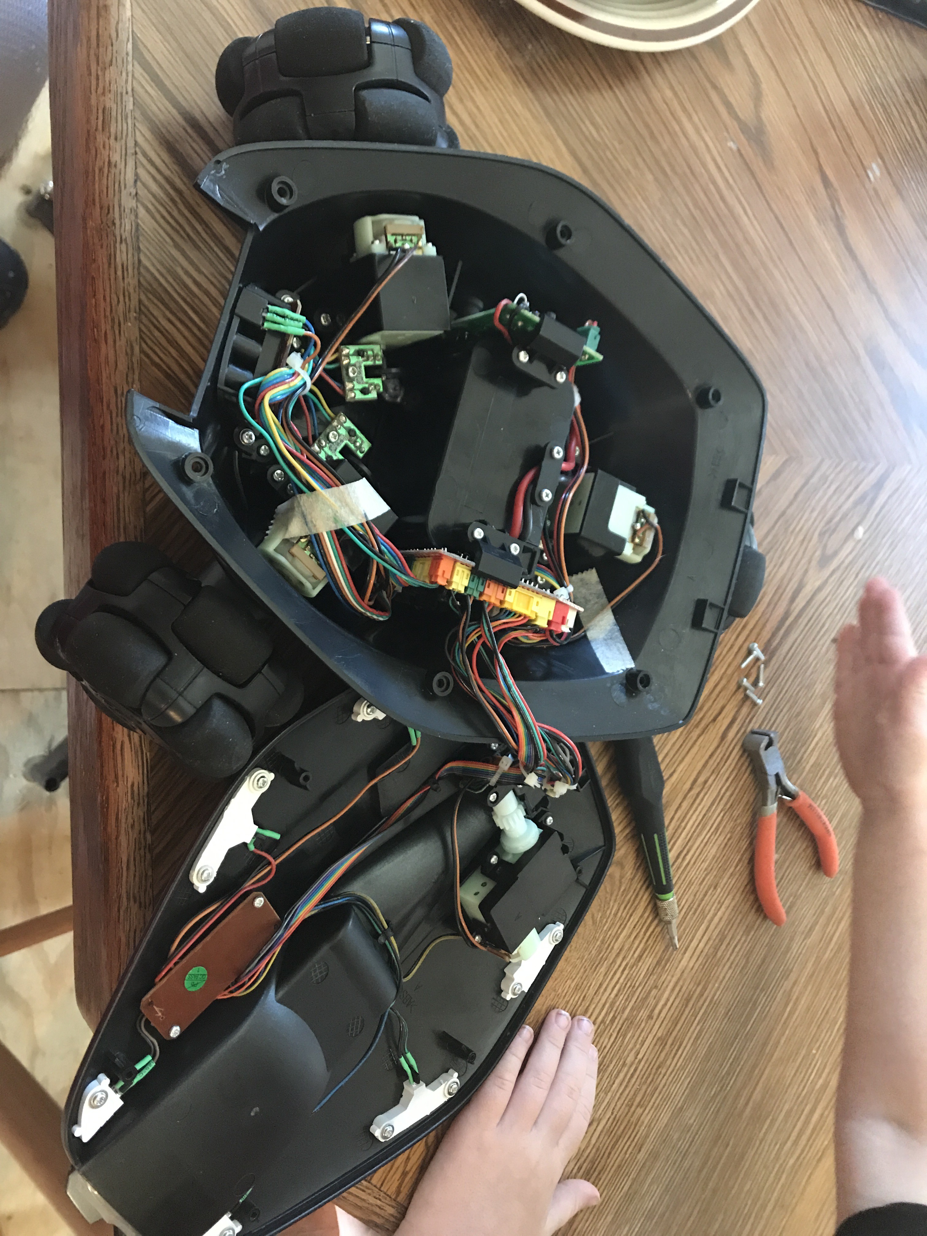
Hacking a Wowwee Rovio Teardown
10/08/2018 at 03:31 • 0 comments![]()
![]()
![]()
![]()
![]()
![]()
![]()
![]()
![]()
![]()
![]()
![]()
![]()
![]()
![]()
![]()
![]()
![]()
![]()
-
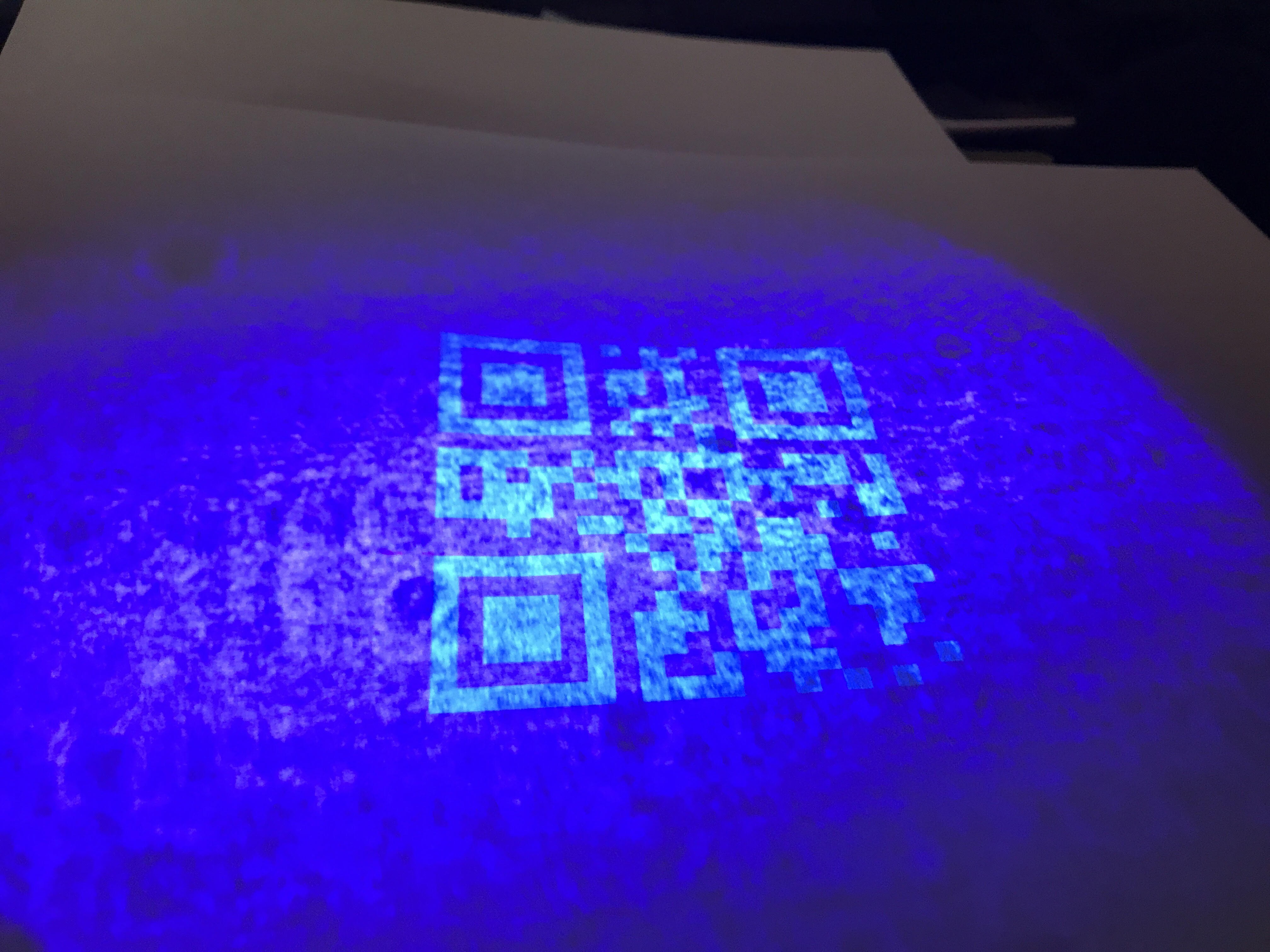
New Printed Codes versus Old Hand Drawn
10/05/2018 at 16:53 • 0 comments![]()
![]()
-
Laser scanning the invisible codes
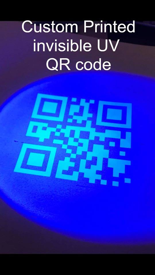
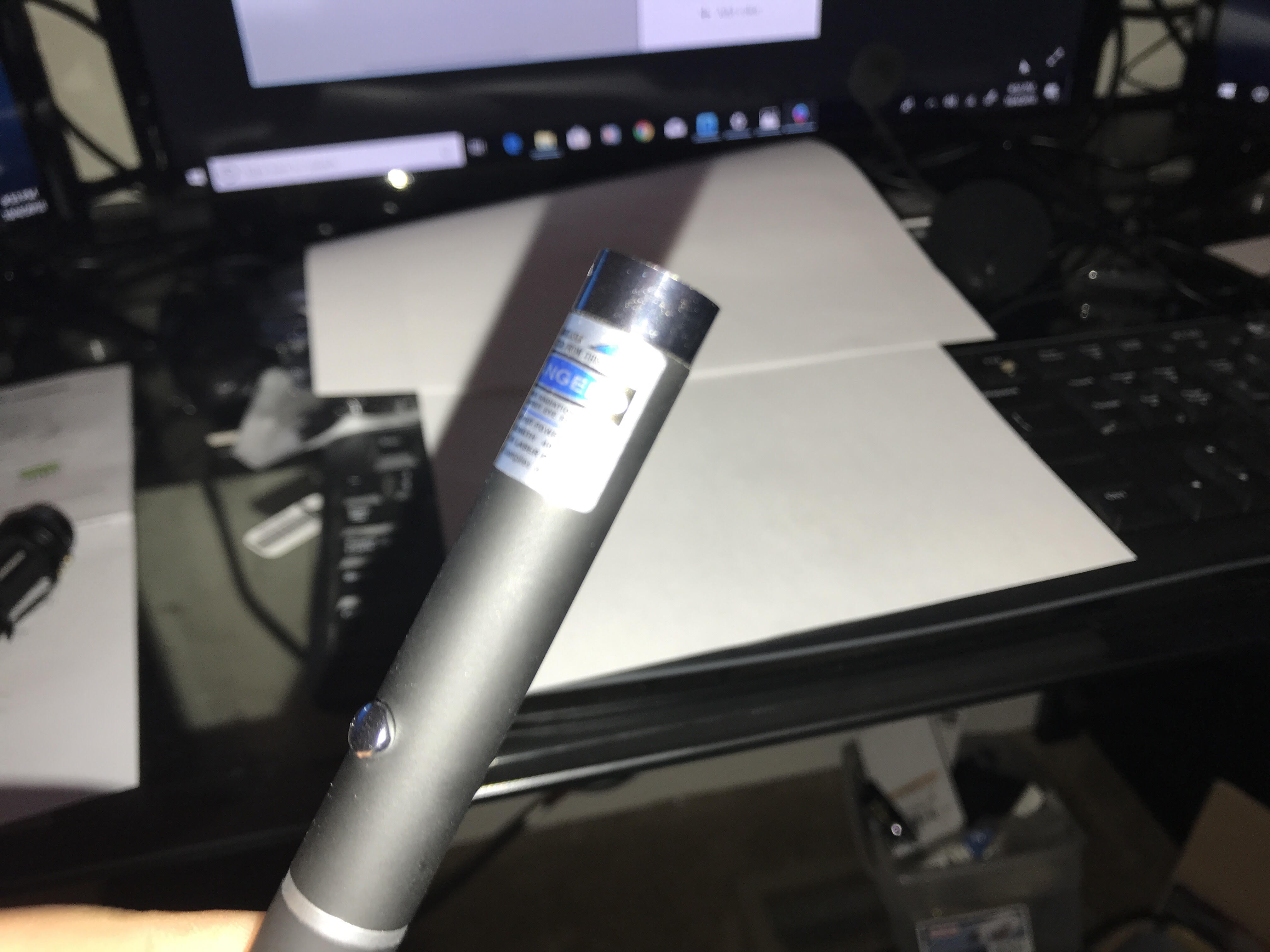
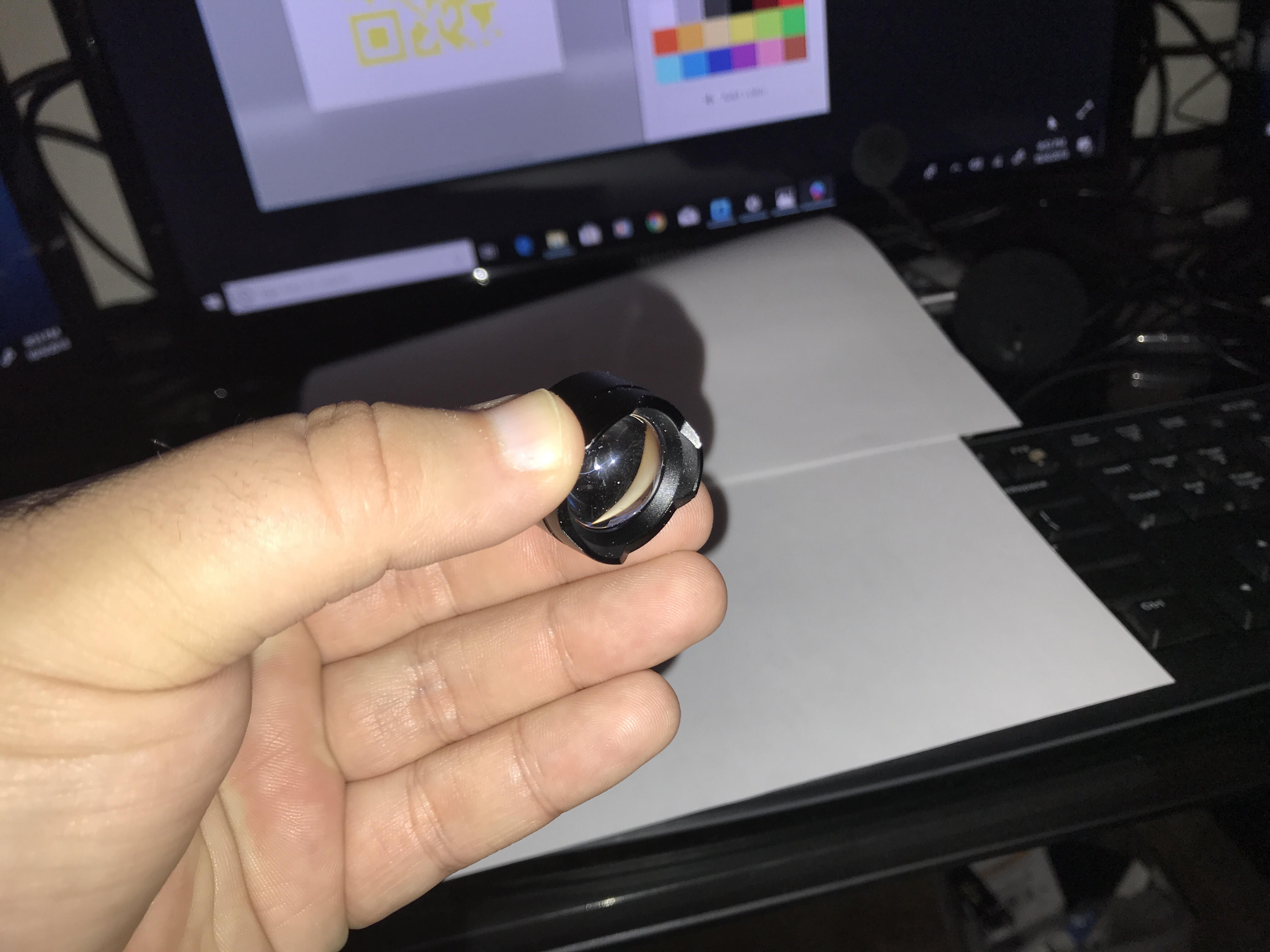
10/05/2018 at 14:57 • 0 commentsLEDs are generally considered power efficient, but in this project I want this method to be more compact and energy efficient. In this case a small laser diode, powered down to a lower output can offer the needed light stimulation to make the codes visible to the camera ,but also using significantly less power than LEDs at 7-10 feet on the ceiling. I used a normal 5 mw laser pointer with the correct 405nm wavelength and tested this out, obviously there are IR versions of the same laser. I used a larger lens to cause intentional beam divergence expansion. This actually worked well but the lens from the flashlight I used apparently was not perfect and caused some "water spot" like marks in the light. I can try cleaning this lens or picking up another one, we will see.
![]()
![]()
![]()
It appears that it works to illuminate the code with the laser diode,but the light needs to be cleaned up. I believe lowering the output to maybe 70 percent and putting a matt filter over the laser would soften the light and make the code more clear, but using less than 1/10 the power.
Invisible QR Code Navigation for Robots 2020
Cheap UV invisible QR codes for indoor navigation of robotics. Print labels from Inkjet Printer and read with a normal camera.