Close
0%
0%

£100 Google Glass using Raspberry Pi

DIY Google glass but done properly

Similar projects worth following
This is an ongoing project, we will post updates as we progress

Wearable tech is becoming the next big thing in the technology world - tied only with the Internet of things. Many people have tried to replicate the technology used in Google Glass, with some fairly catastrophic results. Many projects took a set of video goggles, removed half of them and said that'll do. Other people used systems where they have the entire project stuck to their forehead which I'm afraid to say isn't a great look. One of the version I have seen involving half a pair of video goggles and a Raspberry Pi advertised itself as "$200 Google Glass" only to say in the notes 3D printer required. I'm sorry but I don't think buying a 3D printer as well comes within a $200 budget. Our aim to is create glasses that don't obstruct vision and look good. We will attempt to do this using ready available parts and with a minimum of test equipment and as we are both students, this will be on a minuscule budget.

System Design Document

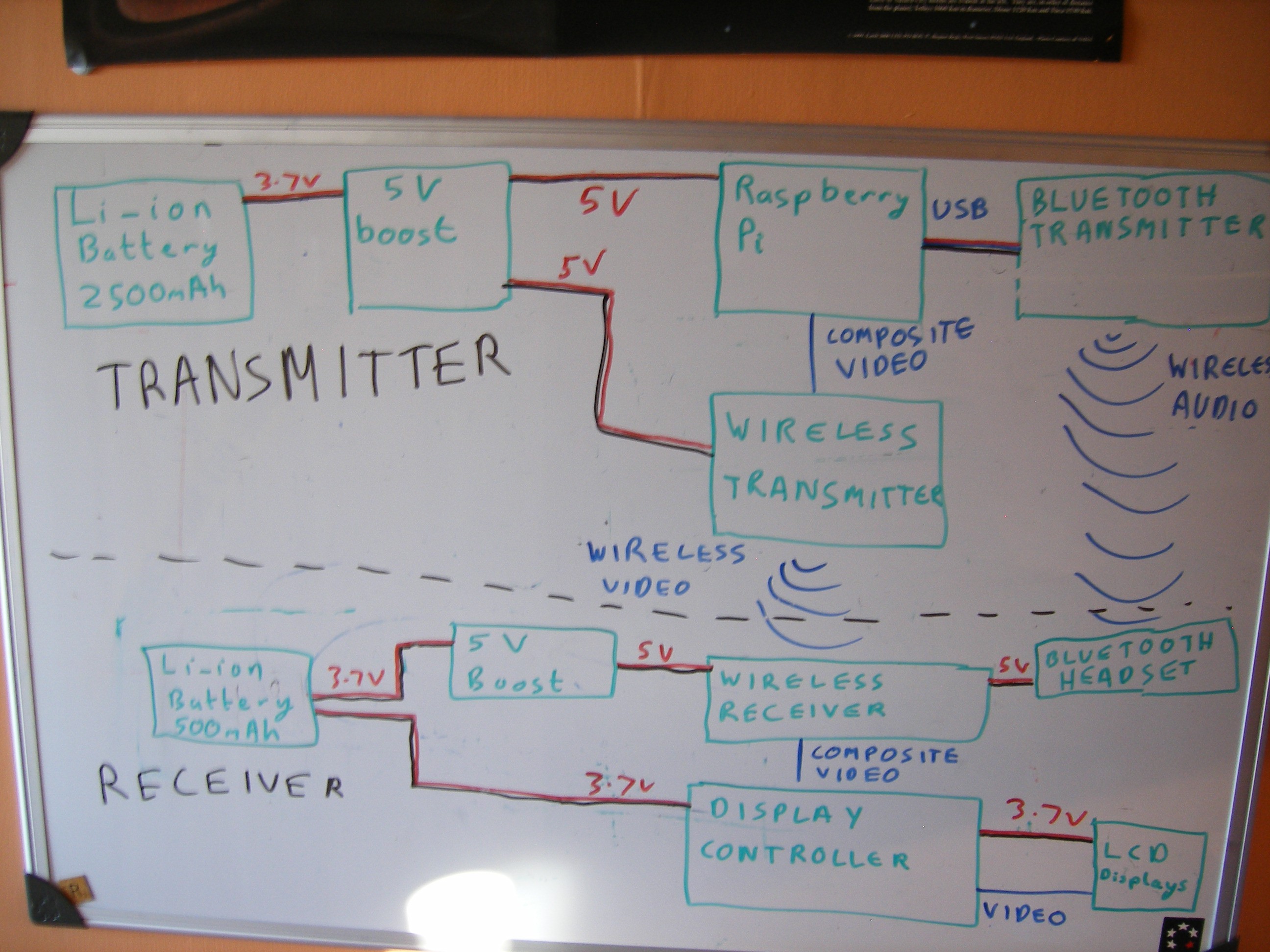
The aim of this project is to create a system which allows anything that would normally be displayed on the Raspberry Pi's screen to be project onto a Head Mounted Display. It is also very important that the project have wireless connections between the two halves (The Raspberry Pi and the display) to allow this project to be as versatile as possible.

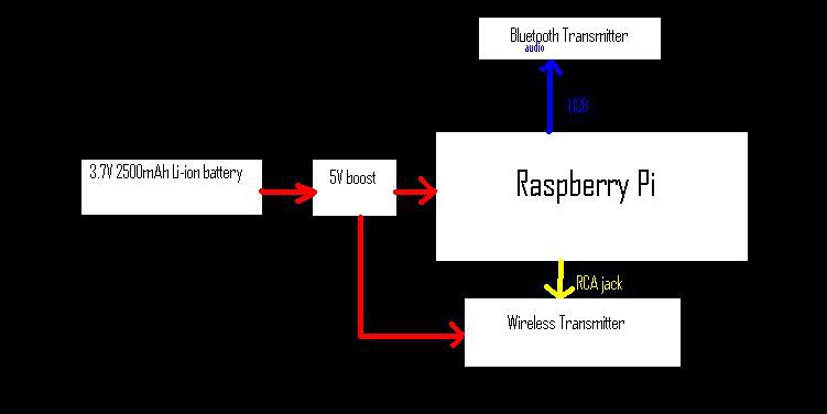
Below is the plan we are following.

As can be follow from out project logs, we have now completed this and are still experimenting with the optics layout and the aesthetics.

See the video below for our progress so far:


The beginning:

As we are just starting out any feedback or suggestions would be greatly appreciated.

Here is our current plans for the project:

Everything controlled via voice commands using Bluetooth microphone

Camera function

Night vision option using IR LEDs

GPS tracker (able to calculate speed/distance etc.)

Integration with fitness devices (e.g. heart rate monitor)

Possibility for linking with smartphones

Possibility for elements of home automation

I’m Dan and I’ll be dealing with the electronics and hardware side of things, my friend Mike will be writing the software for the Raspberry Pi and doing the physics with the lenses and projecting the image.

First of all we purchased a £50 pair of video goggles off amazon.co.uk. (edit: they have now gone up in price slightly to £65)
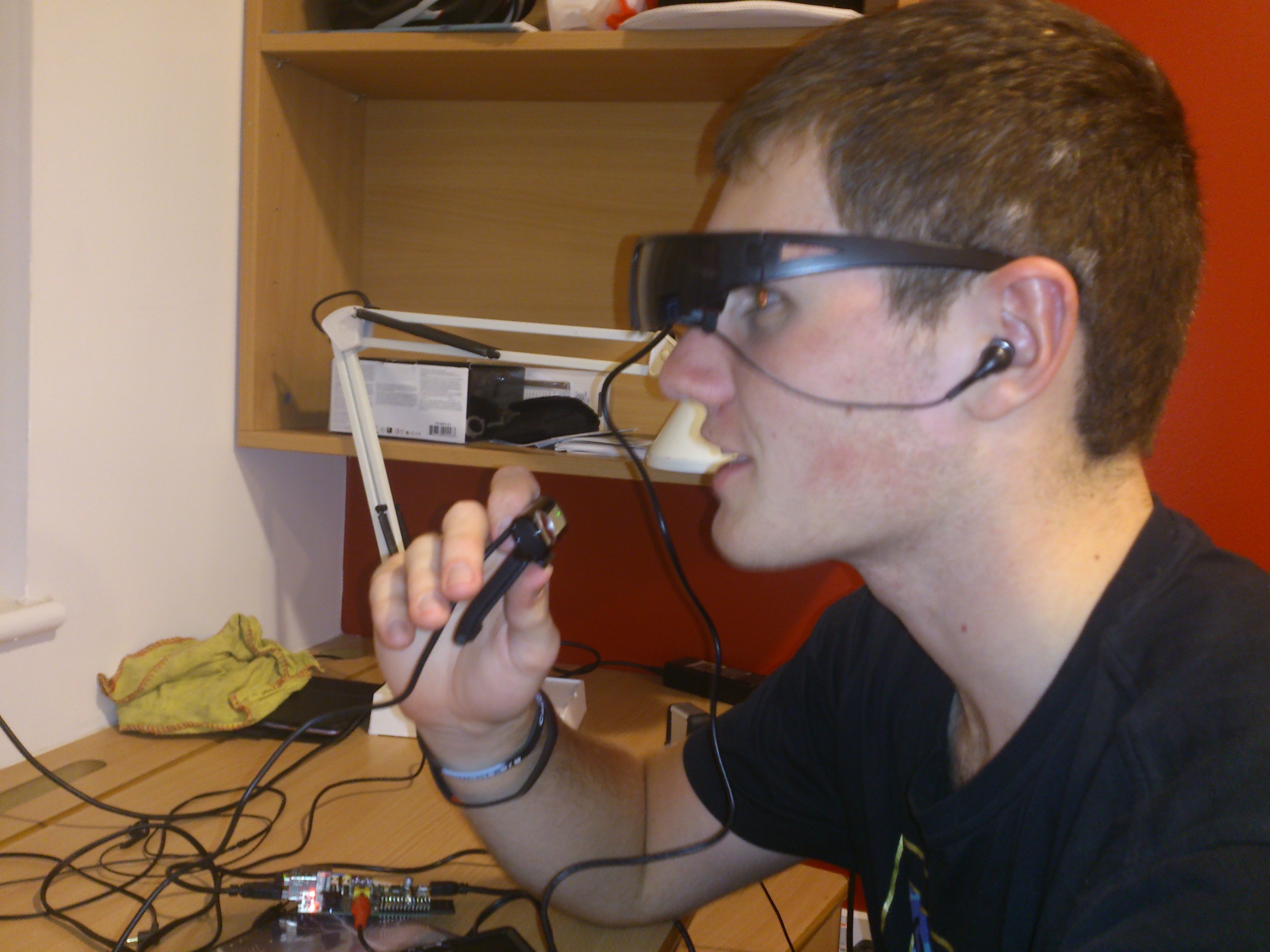
I know that sounds a lot but this will be a massive proportion of the money spent. These have composite video input with dual ear buds for stereo sound. They also include a conveniently small battery pack. Then the fun part came, ripping them apart. After a quick test with a Raspberry Pi, the only thing we had lying around with composite video out, to ensure both screens worked, we started to take them to pieces. This was done by bending the frames slightly to remove the lenses in the sun glasses and then undoing the two screws this revealed. The Health and Safety sticker was then cut with a knife allowing the two halves to separate and to let us have a look at the internal circuitry.
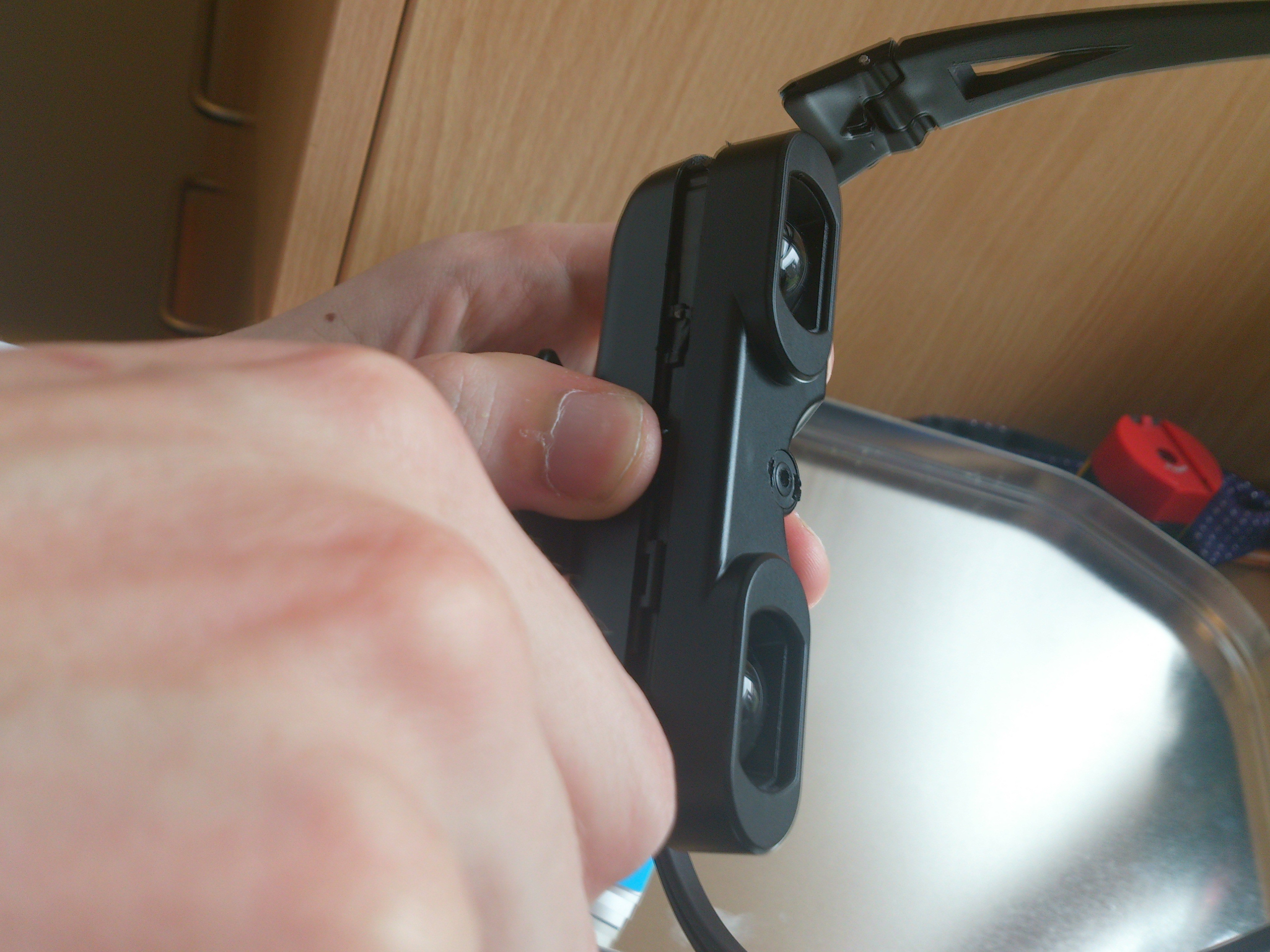
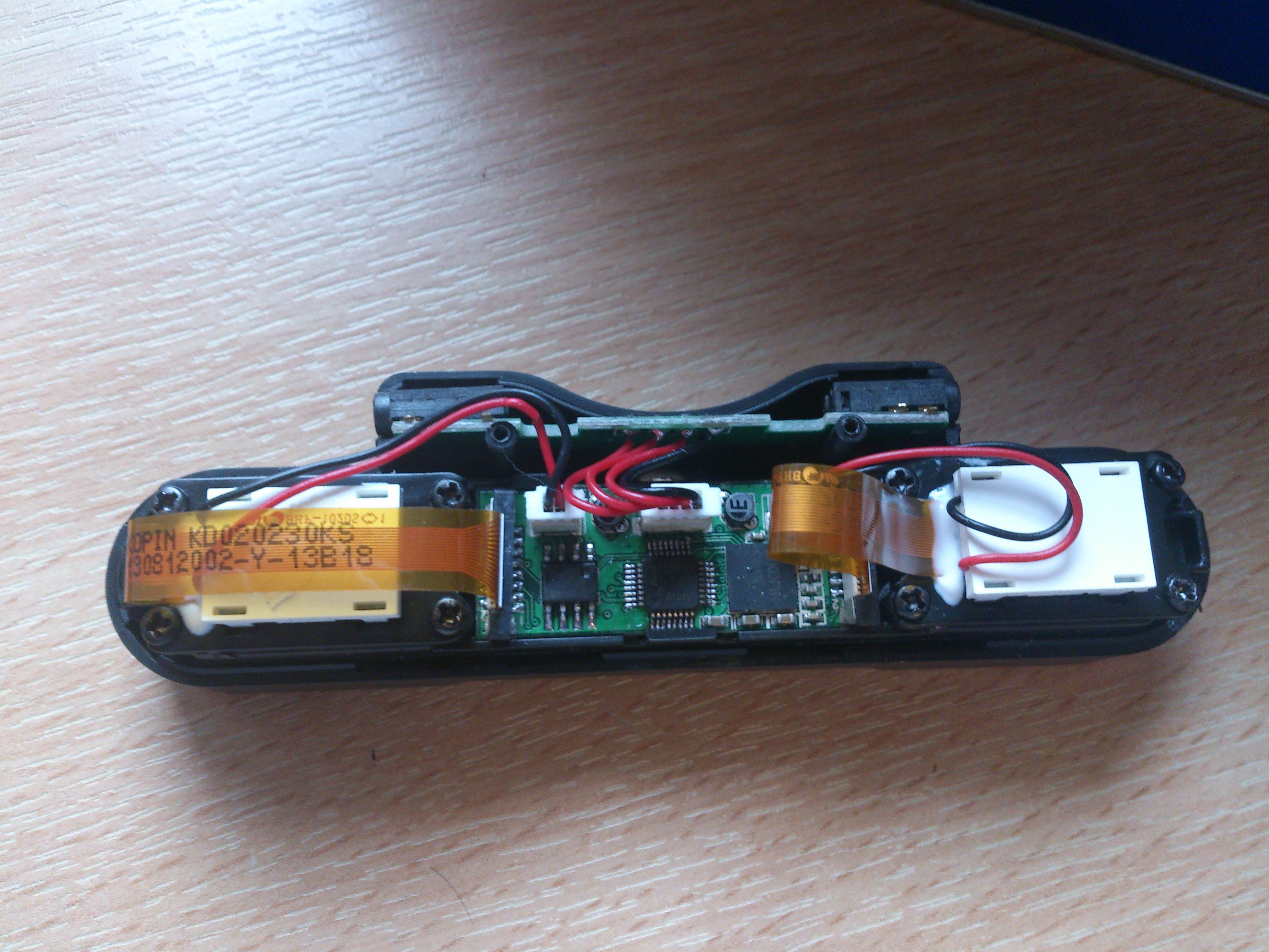
As can be seen, this consists of a breakout board at the top which splits the input into the two audio channels and directs the rest to the display board. This is then connected to the LCDs using a ribbon cable for the data and a two wire connector for power. Following the traces on the breakout board showed that the audio signals were directly connected to the jacks, meaning this board could be replaced with wires and then ignored for the audio signals. As the display board was miniscule, we couldn’t make that any smaller, so we left it as it was. 
  • Shrinking the control board - Part 1

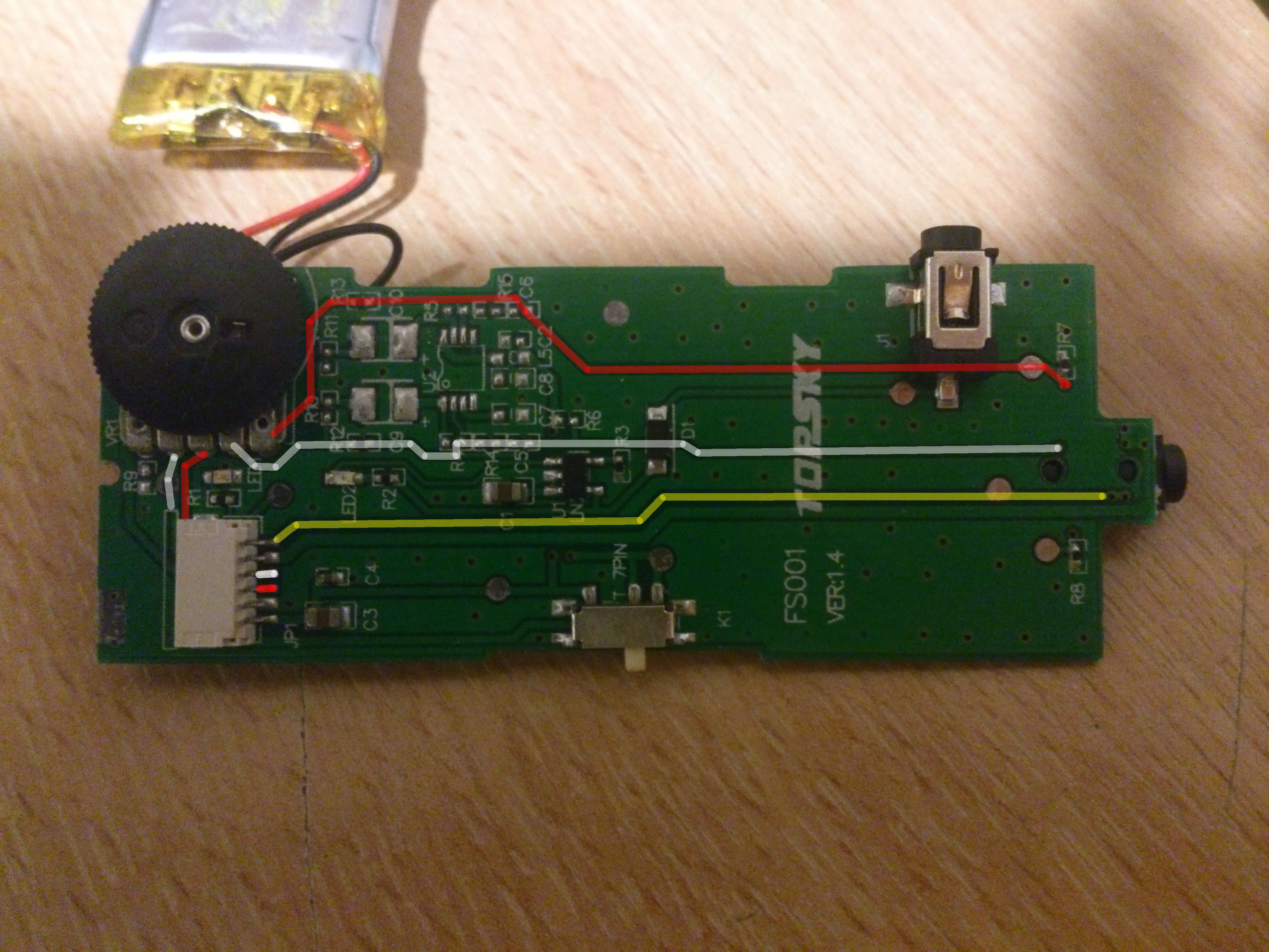
    Now we had got a rough idea of how the electronics worked together, I (Dan) started to look at the control board to see if it could be made any smaller. Opening the case (4 screws – 1 in each corner including one under the health and safety sticker) revealed a board mostly populated by....nothing. It was just about empty. Quick testing with a multimeter showed that the video signal passed straight through, the audio signals went through one resistor and then a variable resistor functioning as a volume control and all 12 components on the board were a charging circuit for the battery.

    Yellow Shows the video going straight through

    Red and white are the two audio lines

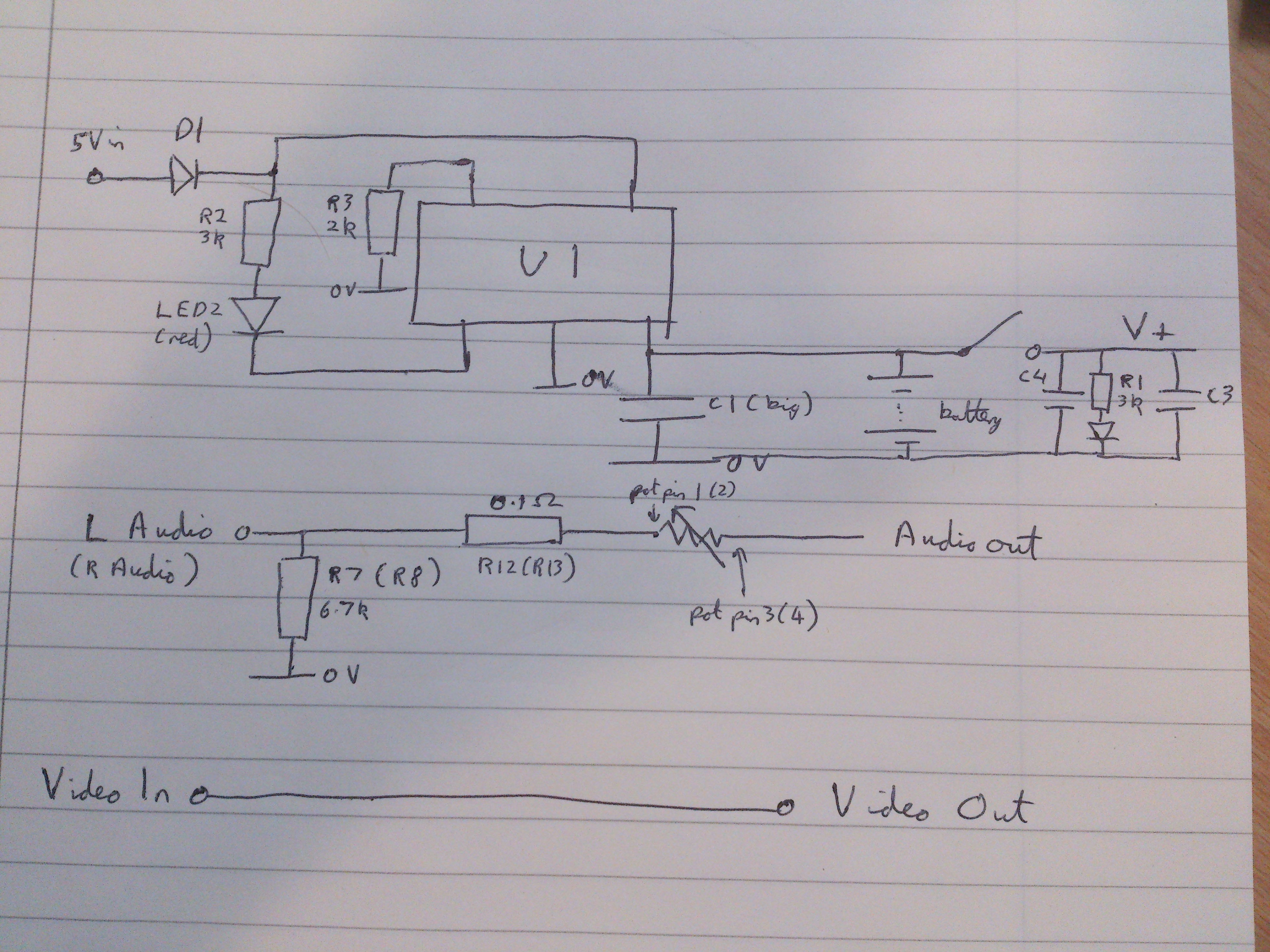
    I sat down and, using only a multimeter with continuity test, managed to create a circuit diagram for the board. From this, I will be able to rebuild the board much smaller as it only needs to have 12 components on it. This micro surgery may be a little ambitious for some but should be no problem for people with experience with a soldering iron and a good magnifying glass. The simplicity of the circuit is shown in the circuit diagram and tomorrow, I’ll see what I can do to shrink this board and see how small we can go.

    As we are uncertain as to what U1 is, the physical layout is used in the circuit diagram. As both audio paths are...

Read more »

  • Electrical tape is a valid construction material...

    danielmcgraw08/20/2014 at 22:23 0 comments

    Now we had the electronic components working, it was time to test it out. For this, I only used the electronic components without worrying about the optics. This meant I temporarily mounted the LCDs outside the glasses just to check that they worked.

    This works with the two units separated across each end of the room with now degrading of the image. The glasses were still very light and comfortable, despite the fact they were covered in insulation tape. This has appeared promising so we will now combine this with the optics to make the Mk2 MUCH more aesthectically pleasing.

  • Night Vision - Part 1

    Michael08/20/2014 at 19:17 0 comments

    One of the aims we stated in the description was to have some sort of night vision capability and some functionality to link with other devices around the home. The beauty of these is that they can be linked together very easily. This is due to the fact that both involve at least one IR LED. The camera uses this to project light this is outside the visible range and so unless another person is using another night vision device you will be invisible. For linking with devices around the home, any remote that you use will almost always use IR light to communicate, therefore bring the glasses into the realm of universal remote and the universe of things.

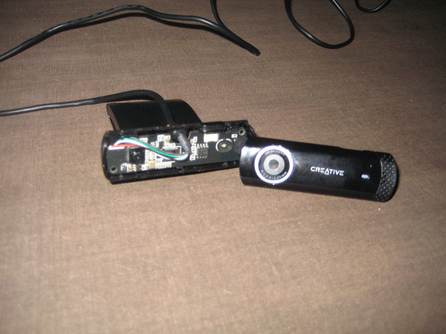
    For now I will be focusing on the Night vision aspect and for this I will be using a simple webcam that I just happened to have lying around. In this case it was a Creative Live! Chat cam HD, though most any one will do. Now I want to point out here that I am not fully integrating this into the project yet, merely producing the capability to be able to do so.

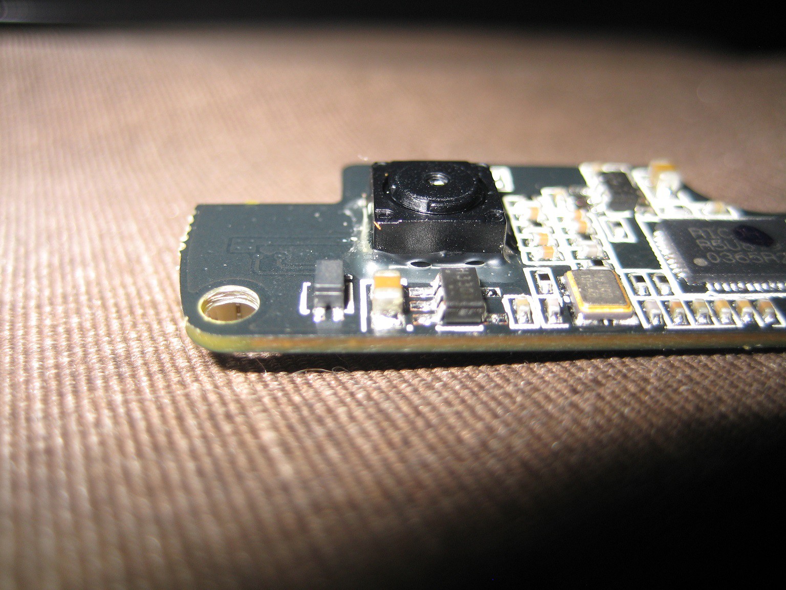
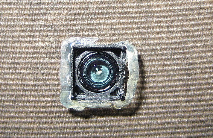
    This first job to do was to take the housing apart, which was simple in my case. There were no screws at all only clips so I could use a knife to get into the gap and lever it open. Once inside I was presented with a circuit board that filled the container, most of which appears like it is needed for the camera unfortunately as this means that it cannot be shrunk very much. The lens assembly covers the sensor and that is the raised section.

    In this block there is the focusing lens and the IR filter (which is what gives it the red tint). This is what needs to be removed, although it may be hidden behind the lens. Great care needs to be taken when removing it if you ever wish to use it again as the filter is very fragile and will smash easily. I myself managed to remove it OK and then dropped it, causing it to smash on the floor. Now there is the option here to place one or two layers of photo negative into the gap where the filter used to be. This will cause only IR light to be passed through to the sensor and render the camera useless in normal light. Due to this I decided to omit this step, but feel free to include it if you wish.

    The lens then needs to be placed back over the sensor, so that images can be formed again. For the time being I have also replaced everything back into the casing for safe keeping until I return to the UK and can find a way to properly integrate it to the project. Also the an IR LED needs to be included so that the camera can see properly in the dark.

    A quick update, I have now managed to get a photo with the webcam using a tv remote to provide the illumination.

  • Optics - Part 2

    Michael08/20/2014 at 11:12 0 comments

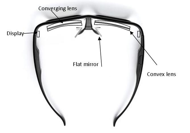
    We had one other problem with our current arrangement and that was the fact that, as the image was reflected, it was mirrored horizontally. We realised the solution to this was to reflect the image first before having it hit the glasses and this also ended up solving the first issue. The only final problem was that of the person’s vision being affected by the use of the lens however that was easily remedied by the addition of a further lens from a set of equally strong (+3.50) reading glasses. The rough sketch of the final set up can be seen bellow.

    We are still experimenting with the design and for now have not included the sunglasses in our prototype for the sake of simplicity; however it is something we are looking at implementing in the future. This is both for the fact that less light will reach the eyes making the screen relatively brighter and also that it looks far better and serves to hide all the electronics.

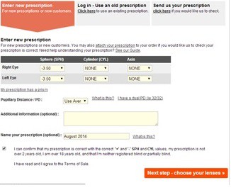
    The reading lenses are from cheap sets you can buy in many local stores and the others are from an online prescription service that allows you to order glasses cheaply to a specific strength. This process can seem complicated but below is an image of how it should look when completed and is in fact very easy. The only number that needs to be modified is the SPH or spherical number, and this needs to be -3.50. The others should be 0 and the PD (pupil distance) is irrelevant and can be any number you like.

    When buying/ordering the glasses buy the cheapest frames you can as they will not be needed at all for the project and can be thrown away as soon as the lenses are removed. To modify this setup for anyone who does require glasses already is very easy, all that needs to be done is to change the strength of the reading glasses so the difference in strength between the two matches you’re prescription and this can be done separately for each eye. For example I have -1.50 eyesight and so I would get +2.00 reading glasses to compensate (-3.50+2.00=-1.50).

    The final consideration with the lenses is to try to find ones that match each other closely in size to avoid as much visual distortion as possible.

  • Optics - Part 1

    Michael08/20/2014 at 09:01 0 comments

    Hi its Michael here.  Sorry I haven't posted any updates in a while but I have been out in Egypt for the past month and a half and so have had very little access to the internet.

    One of the major challenges in producing a system like Google Glass is the projection of the image so that it can be seen. If there was no need to be able to see through the image our job would have been incredibly simple as all that is needed is the stock high magnification lens that comes with the glasses. However, for our task we have decided that placing the screen to the side allows for a much greater ability for the image to be used simply as an overlay to the real world keep it augmented reality rather than virtual reality.

    The main issue we had here was making sure that we could have the screen quite close to the eye while still having the image placed at the infinity focus point and still having the image large enough to see. We played around with various magnifying mirrors and some quite complicated mirror arrangements to try and find an ideal balance. Despite this, even with a 15x mirror, we were unable to properly bring the screen into focus at the desired size. The other problem with this set up is that we would have had to very carefully cut the mirrors to the correct size without affecting their optical properties.

    During this experimentation however, we did stumble across one surprising fact. It happened while trying to test a setup of the mirrors and we needed one more which we couldn't find. To resolve this we decided to try using my glasses (for shortsightedness) instead. We found a curious effect that the image produced was far bigger and in fact the focus had been pushed too far away so that we were in fact looking at a virtual image which I could not focus on. This gave us an idea and so we managed to get a hold of different strength glasses and compared their effects on a reflected image. It turned out that the stronger the glasses the greater the magnification and focusing effect, with -3.50 glasses producing a large in focus image at a distance of about 3 inches. Now obviously this is too large a distance to have a reflecting screen from your face but it was still a start.

  • Aims

    danielmcgraw08/19/2014 at 18:05 0 comments

    Now that we have the main hardware (minus the optics) all working. We aim to explain how this project can be modified to suit your needs.

    The main advantage of this design is that all the parts are readily available (links in the components section) and that it uses the Composite Video display on the Raspberry Pi, this means these can be used with any existing design without the need for any changes. Every project that has been built with the Raspberry Pi can be used with these Glasses as it uses the existing display and a few parts which are simple to connect. The use of voice protocol and portability mean the Smart Glass can easily be integrated and the addition of a WiFi dongle make the possibilities limitless.

    For example, using this to control your music. You could connect your Smart Glass to the WiFi and have a second Raspberry Pi acting as the server with the GPIO connected to the buttons on the remote. If you were to say "Volume UP" the Bluetooth microphone would pass the audio to the Raspberry Pi in your smart glasses. This could send the signal through the Wifi, telling the Raspberry Pi controlling the sound system to "press" the button and increase the volume. 

    Another example is access to Google search, the microphone would detect your speech and use the "Search by microphone option" the Google servers would then decode the search phrase just as in Google Glass (but much cheaper!)

  • Hardware Video Overview

    danielmcgraw07/11/2014 at 11:36 0 comments

    Hi guys,

    Just wanted to show you what the project is looking like at the moment. Any questions / advice / things you want to see in this project, just leave a comment and we will be grateful for your feedback. One of the big things was making sure that this worked using any operating system on the Raspberry Pi and by designing it to use the RCA output, once this is built, it should be able to plug into any Raspberry Pi and work instantly so this can be easily combined with any other project.

  • Wireless Success

    danielmcgraw07/08/2014 at 12:02 0 comments

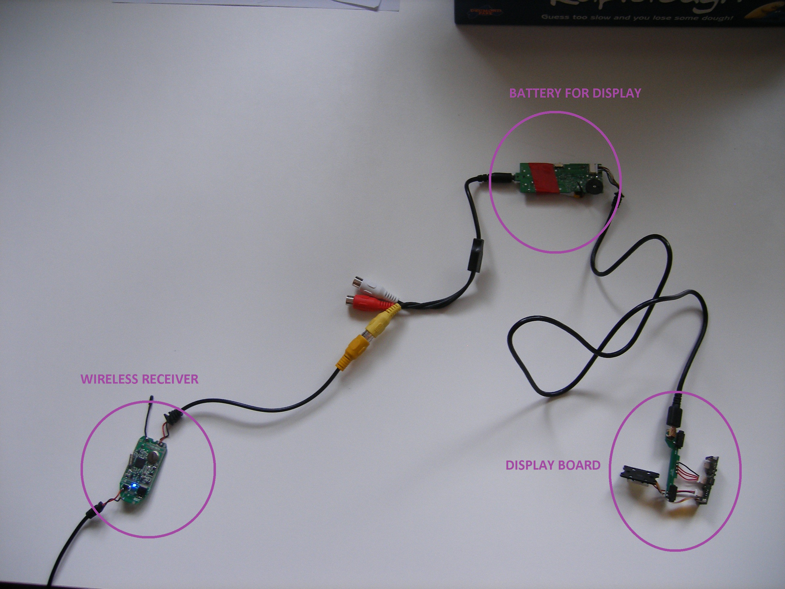
    I have now tested the two wireless modules and things are going very well. For testing the transceiver modules were powered of 12V to ensure they worked before modifying them and everything was connected up using the provided connections although this made the test project quite large. 

    In the room next door, I assembled the receiver section to make sure that it worked.

    This worked very successfully with no problems with the image. Now to shrink both of these portions down. The optics STILL have not yet all arrived so that has had to be put off again. 

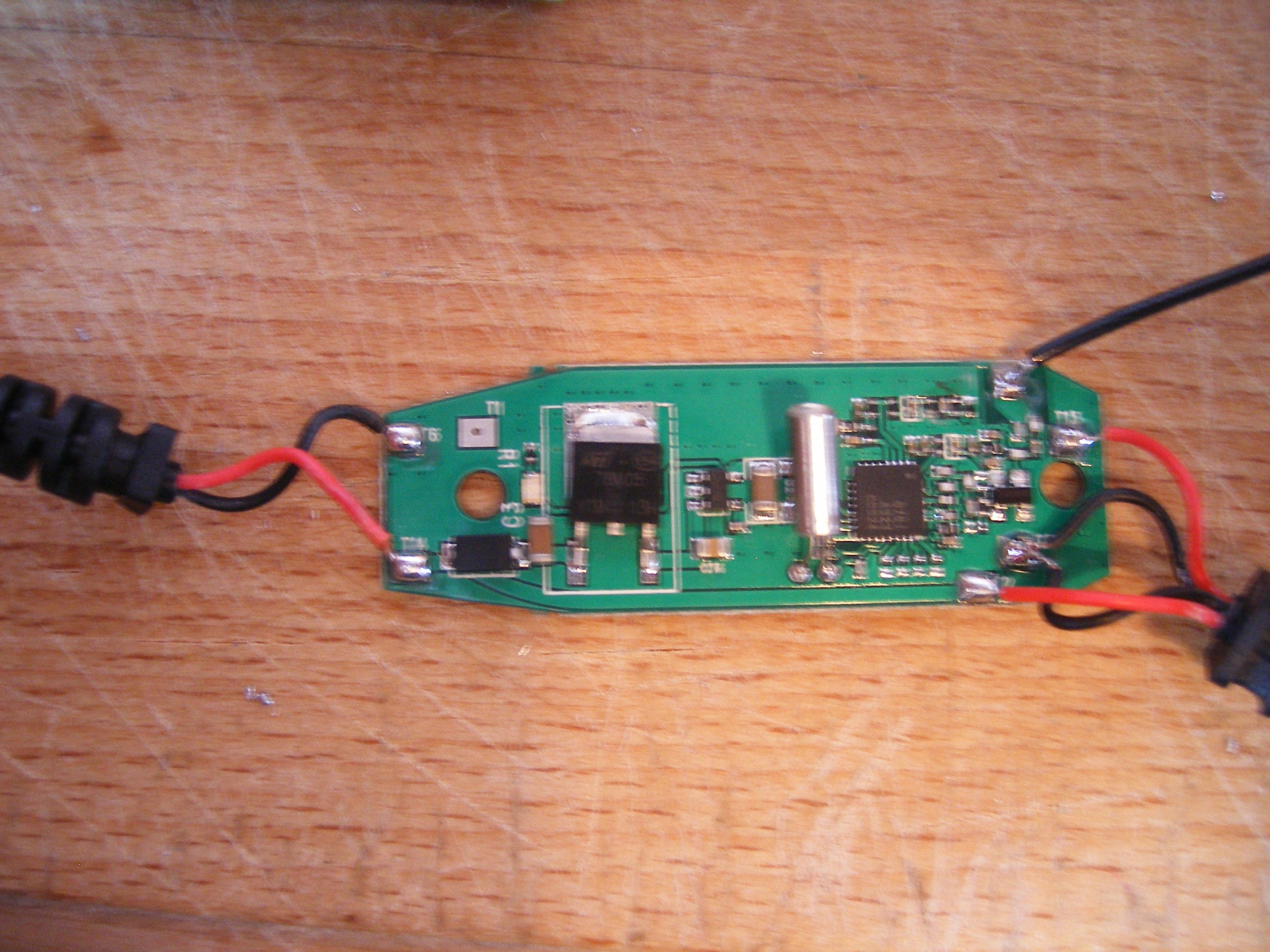
    Both the wireless board use a 7805 regulator to provide 5V. 

    This is the large IC on the left of the board where 78M05 can just be read. We will provide power on the bottom right pin which is the 5V output to prevent us having to step up the power only for the 7805 to waste energy stepping back down. I will then re-run the battery test program to see how long the battery lasts doing what will be typical for it in this project. EDIT: This has now been complete with a battery life of 192 minutes (just over 3 hours) so this is looking very promising.

  • Testing, Testing 123

    danielmcgraw07/08/2014 at 10:43 0 comments

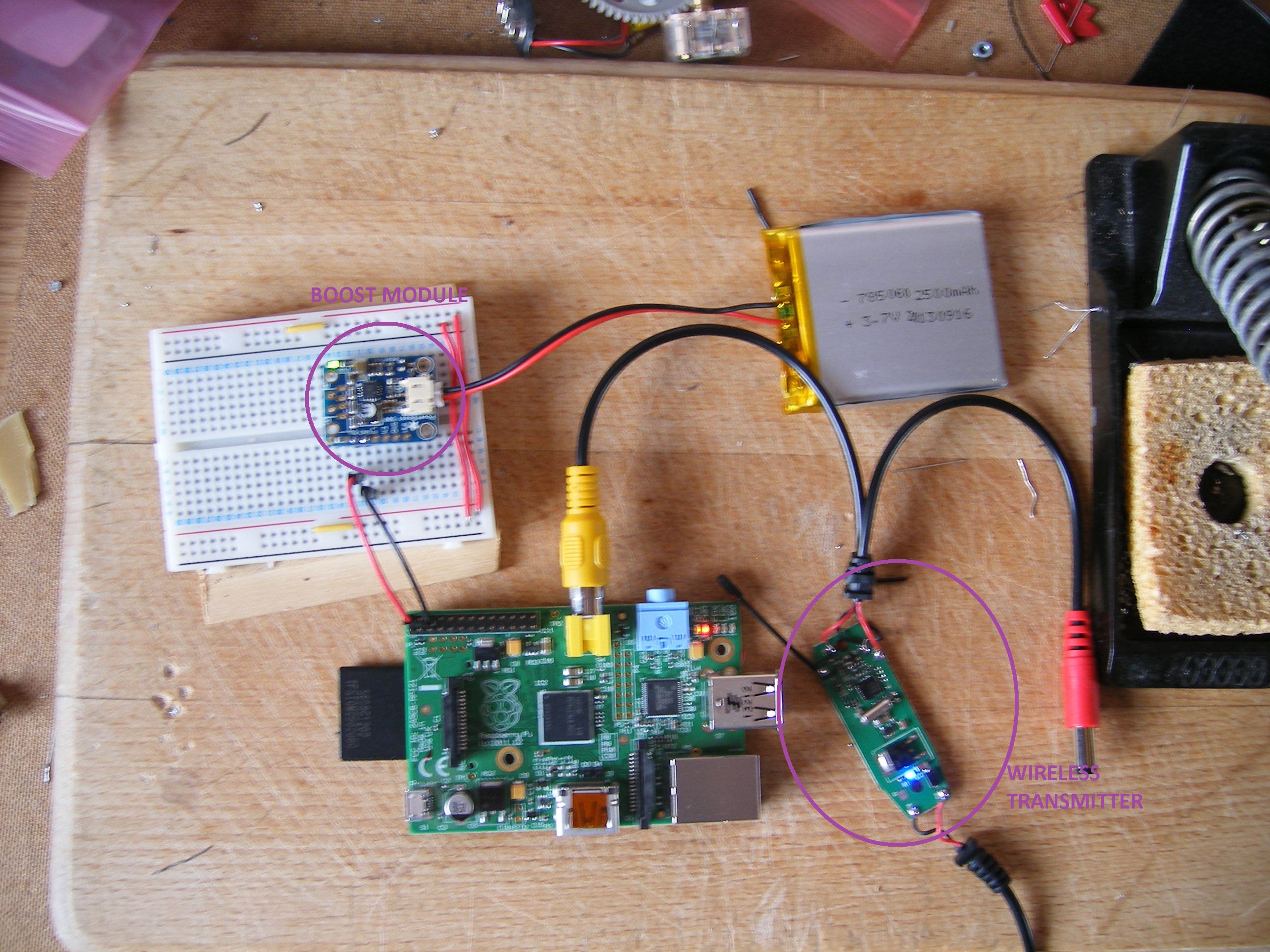
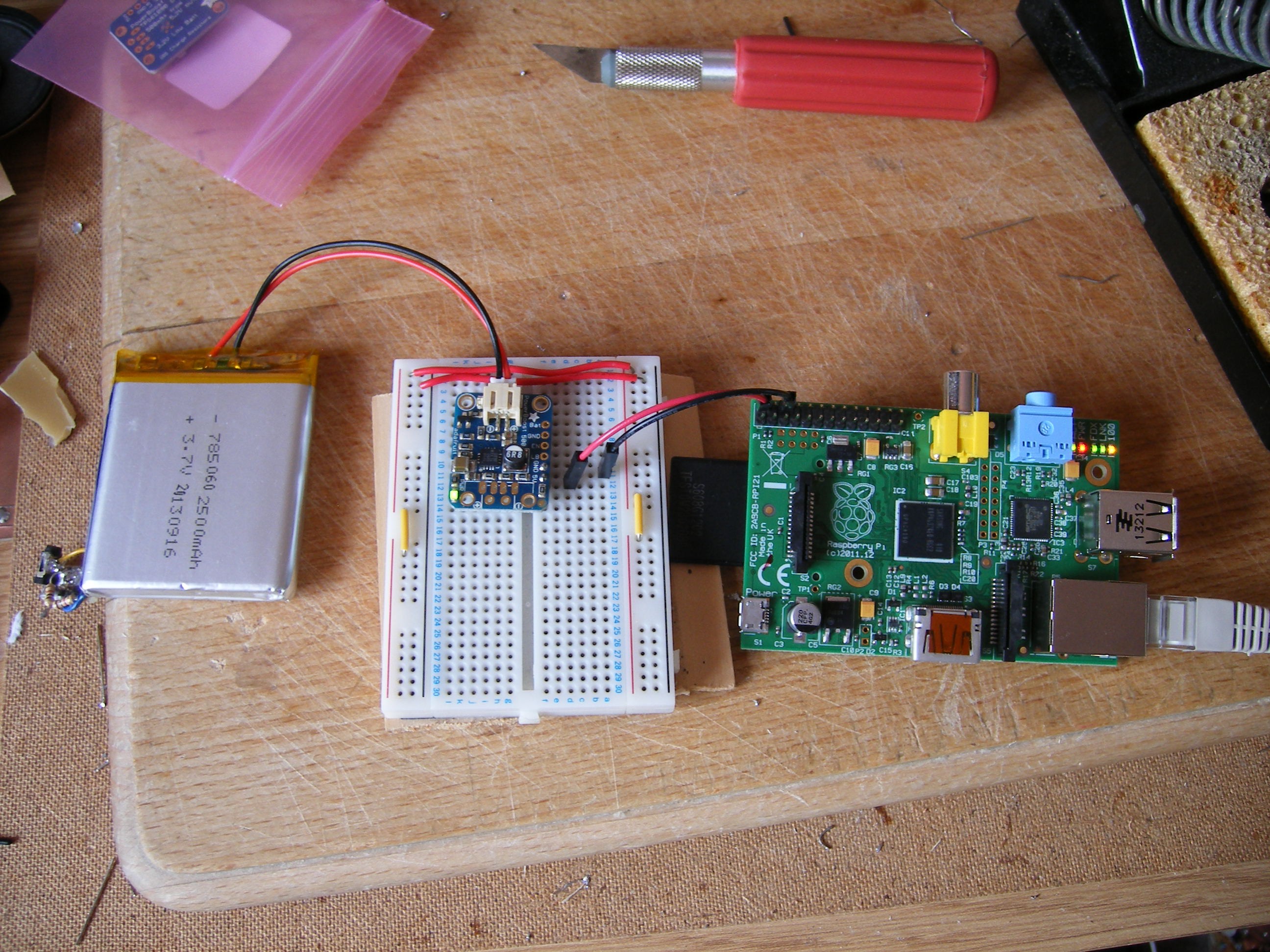
    The first thing we wanted to test was the battery life when the Raspberry Pi was powered from our 2500mAh battery. The Raspberry Pi is advertised as drawing 700mA so we expected about 3.5 hours. To test this, the Raspberry Pi was powered from the battery and boost converter with the only other thing connected being an Ethernet cable to receive the data. The setup is shown below with the battery on the left, the boost circuit on the breadboard providing power to the Raspberry pi via the GPIO.

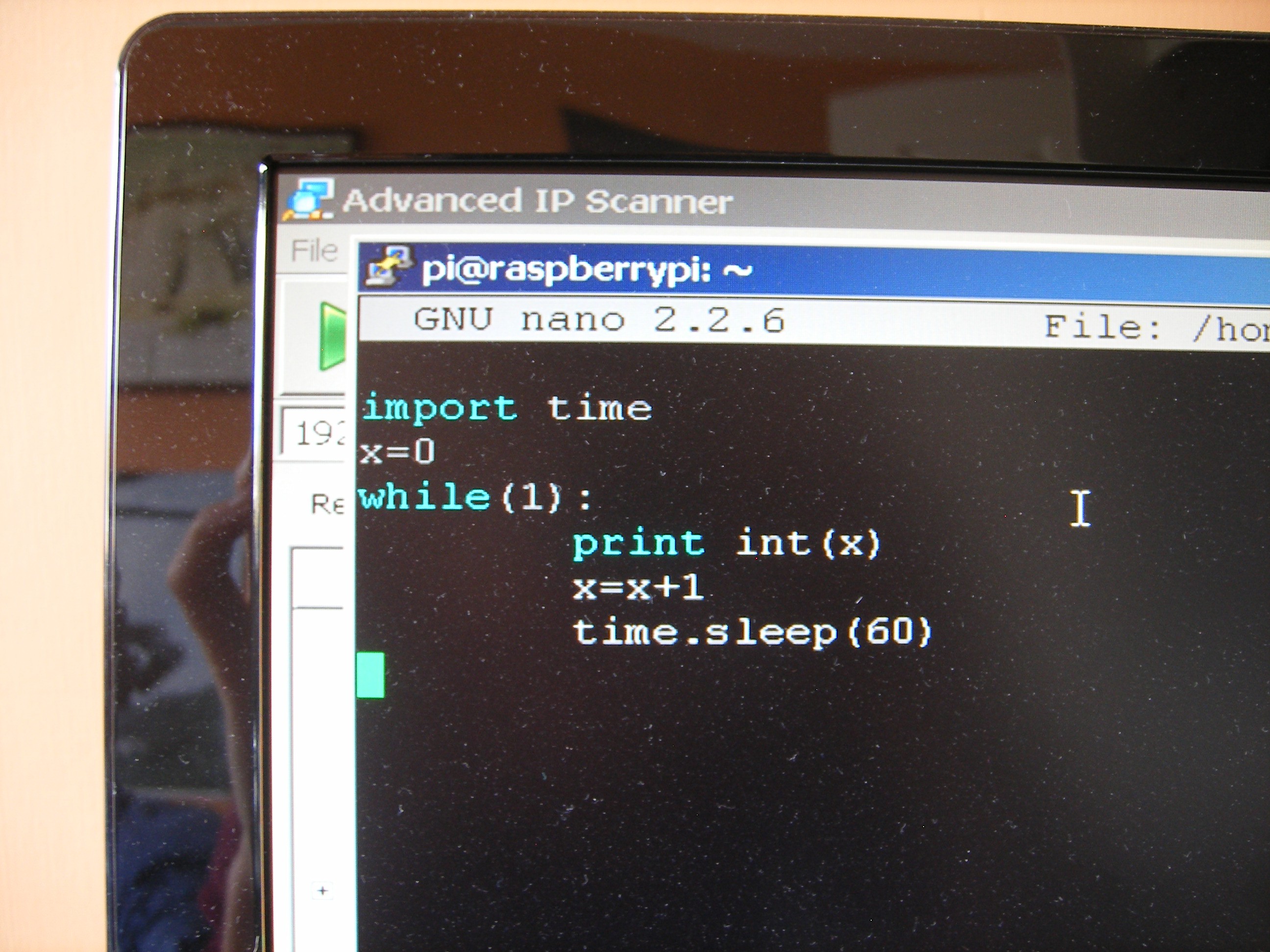
    I ran this simple python program which sent data to my desktop via SSH. (parts after # indicates an explanation, not the actual code)

    import time #time library allowing the RPi to wait a certain length of time

    x=0 #set up a value for x

    while(1): #forever loop

    print int(x) #send x to desktop

    x=x+1 #increment x

    time.sleep(60) #wait for 60 seconds or 1 minute

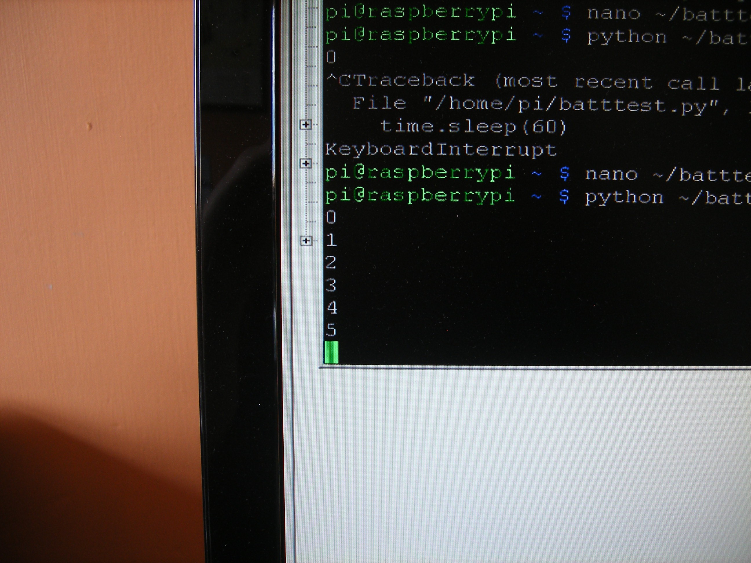
    This was then left for about 6 hours to run and the last value of x received on my computer was 248. This means the Raspberry Pi was on for 248 minutes since the program was started so the battery lasted about 4 hours. This is more than expected but that is probably due to the fact that this was the only thing being run by the Raspberry Pi so the processor could run on very minimal resources. When the transmitter and Bluetooth are connected and the Pi is running a more complex program, I expect this to reduce to about 2.5 hours.

    Our microsurgery on the charger circuit has proved to be unsuccessful as the metal parts came off certain components so we have purchased a Li-Po battery charger from Pimoroni (though they appeared to be Adafruit products) along with the large battery for the Raspberry Pi and 2 boost circuits. Once we have the Raspberry Pi working, I shall try and shrink it down but this will be done in small steps and now exams are over, I will try to update this page much more regularly.

     Test software (Top) Results from the test program (Bottom)

  • Power Progress

    Michael06/23/2014 at 10:41 0 comments

    Hi,

    We are slowly making progress, exams at the moment have meant we haven't had any spare time. However, we have found a suitable battery for the Raspberry Pi and 5V boost converter so they are on their way.

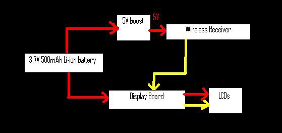
    The datasheet from the wireless modules stated that they needed 12V @ 200mA. Opening them up revealed a 7805 voltage regulator, this works by drawing the current required by the circuit and wasting the excess energy as heat. By connecting the power after the voltage regulator we can waste less energy as very little will be wasted as heat and we can power them off 5V which we need to generate anyway.

    This has simplified the design and the layout (at the moment can be seen below) Red indicates power, yellow indicates video signal.

  • Shrinking the control board - Part 2

    Michael06/13/2014 at 21:27 0 comments

    THIS IS NOT USED IN THE FINAL PROJECT. IT IS PROVIDED ONLY FOR REFERENCE. THIS WAS THE ORIGINAL PLAN BUT WE HAVE HAD TO CHANGE OUR IDEAS TO MAKE IT BETTER. For information on the new charging circuit see the project log labelled "Testing, Testing 123"

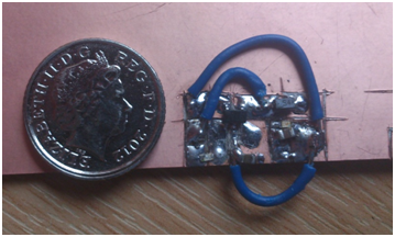
    Now we had the schematic of the control board sorted, it was time to make it MUCH smaller. Using the schematic we had worked out using a multimeter, we placed the main IC onto the board and, using only a Stanley knife and a fine pair of tweezers, we remade the board. The board measures 16mm x 8mm and is shown next to a 5 pence piece for reference. The wire will probably be replaced at some point but it’s the only stuff we had lying around.

    While extremely tricky to solder, this was completed in about 1 hour with the two of us and does work. Again, the only tools used were a Stanley knife to cut the board into islands to solder the components between and a fine pair of tweezers to hold them.

    This was managed with only 1 injury, a minor burn on Mike’s finger but otherwise it went about as well as we could have hoped (especially as this was Mike’s first time within 100ft of a soldering iron!). This shows that even with tiny surface mount components (see the tiny black blob at the end of the arrow, that’s one of the resistors!) it is still possible to be used without a circuit board.

    Good news, the wireless display components have arrived today and Mike’s been writing more code so we hope to have some more updates for you over the weekend. Unfortunately, the parts for the optics have taken longer than promised to arrive so we will aim to post a video showing how those work about the middle of next week.

View all 10 project logs

Enjoy this project?

Share

Discussions

J Groff wrote 12/12/2014 at 11:32 point
rPi seems really underpowered at this point, seems like there are many other SBCs way more powerful in the same footprint

  Are you sure? yes | no

Jasmine Brackett wrote 08/16/2014 at 00:09 point
Hello Daniel and Michael, please review your project documentation to ensure it has everything we require for it to be considered for the next round of The Hackaday Prize.

By August 20th you must have the following info on your project page:
- A video. It should be less than 2 minutes long describing your project. Put it on YouTube (or Youku), and add a link to it on your project page. This is done by editing your project (edit link is at the top of your project page) and adding it as an "External Link"
- At least 4 Project Logs
- A system design document. Please highlight it in the project details so we can find it easily.
- Links to code repositories, and remember to mention any licenses or permissions needed for your project. For example, if you are using software libraries you need to document that information in the details.

You should also try to highlight how your project is 'Connected' and 'Open' in the details and video.

There are a couple of tutorial video's with more info here: http://hackaday.com/2014/07/26/4-minutes-to-entry/

Good luck!

  Are you sure? yes | no

mistertime wrote 06/11/2014 at 13:44 point
Crap, I was gonna do this.

  Are you sure? yes | no

Mike Szczys wrote 06/09/2014 at 18:45 point
This is an awesome topic for The Hackaday Prize. I excited to see it take shape! I especially like the thought of moving the bulk of the computing power somewhere other than the frames of these things.

  Are you sure? yes | no

Michael wrote 06/10/2014 at 12:39 point
Mike,
Thanks for your comments. The moving of the computing power somewhere has made things slightly more complicated in terms of the actual displays as everything needs to be controlled wirelessly. However, with Bluetooth and other standardised wireless protocols this is not too much of a problem. Our aim is to make the glasses themselves as small as possible and our current designs for the layout for the Raspberry Pi (and battery) result in a device about the same size as an iPhone. As can be seen from our video, the components that actually require placing on the glasses are all tiny. These are the battery (with charging circuit), the smallest display board and the LCDs themselves. The only other device required is a receiver for the video display and this can be made very small as tiny wireless RCA receivers and transmitters are available on Amazon for a very reasonable cost. We will probably buy one of those for testing and then see if we can reduce the size any further ourselves.

  Are you sure? yes | no

zakqwy wrote 06/09/2014 at 16:14 point
It sounds like aesthetics are important; have you started putting together a model of the final product? How do you plan to construct the hardware enclosure?

  Are you sure? yes | no

Michael wrote 06/10/2014 at 12:38 point
Aesthetics are obviously very important but how the final project looks will be determined mainly by the arrangement required by the optics i.e. the system of mirrors and lenses to project the image into your eye. We pretty much have this finalised and we aim to release another YouTube video and update showing a first design of the layout of the actual glasses very shortly.

  Are you sure? yes | no

zakqwy wrote 06/10/2014 at 15:30 point
Sounds good. Looking forward to the video!

  Are you sure? yes | no

Similar Projects

Does this project spark your interest?

Become a member to follow this project and never miss any updates