 danielmcgraw
System Design Document
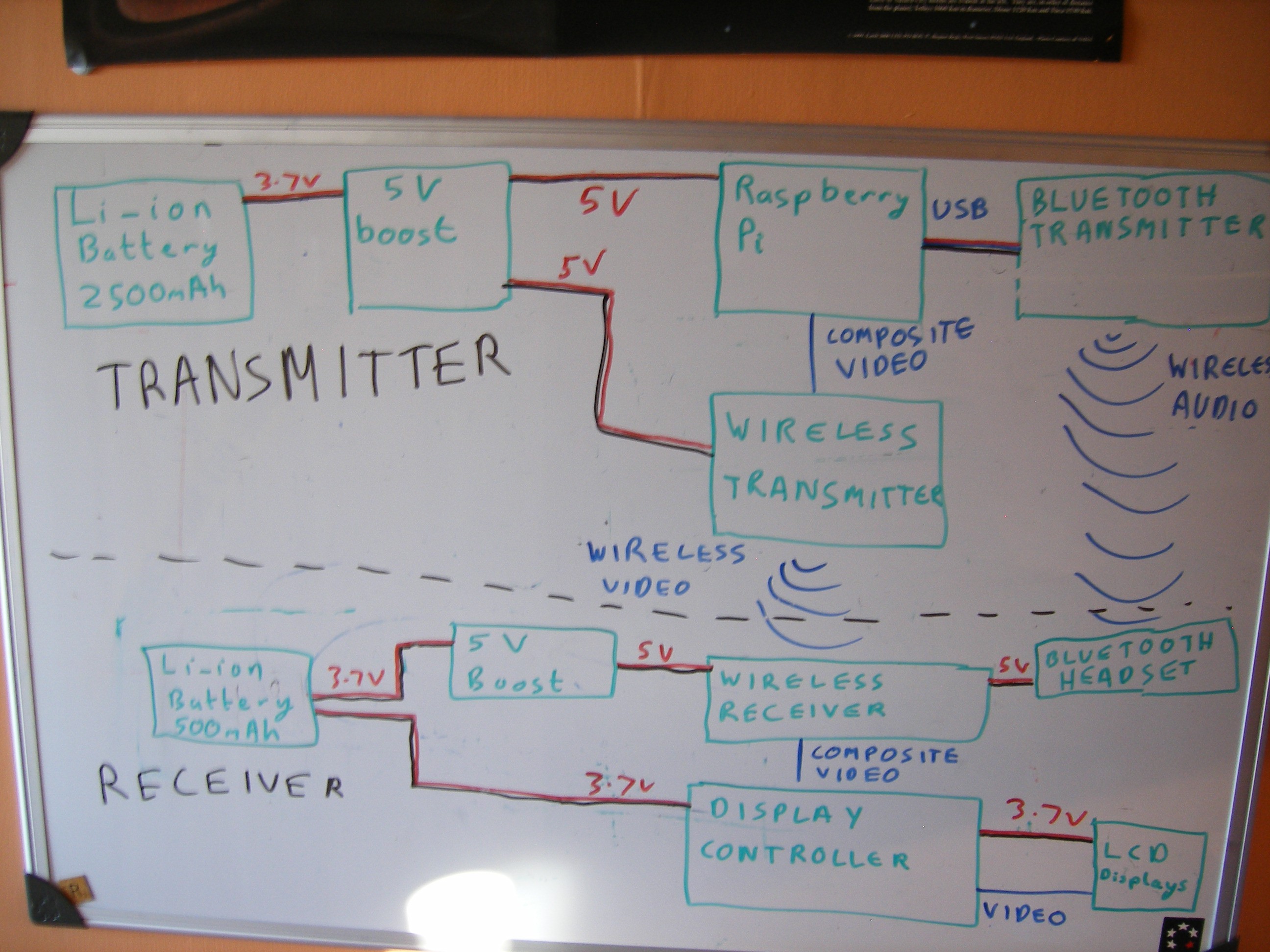
The aim of this project is to create a system which allows anything that would normally be displayed on the Raspberry Pi's screen to be project onto a Head Mounted Display. It is also very important that the project have wireless connections between the two halves (The Raspberry Pi and the display) to allow this project to be as versatile as possible.
Below is the plan we are following.
As can be follow from out project logs, we have now completed this and are still experimenting with the optics layout and the aesthetics.
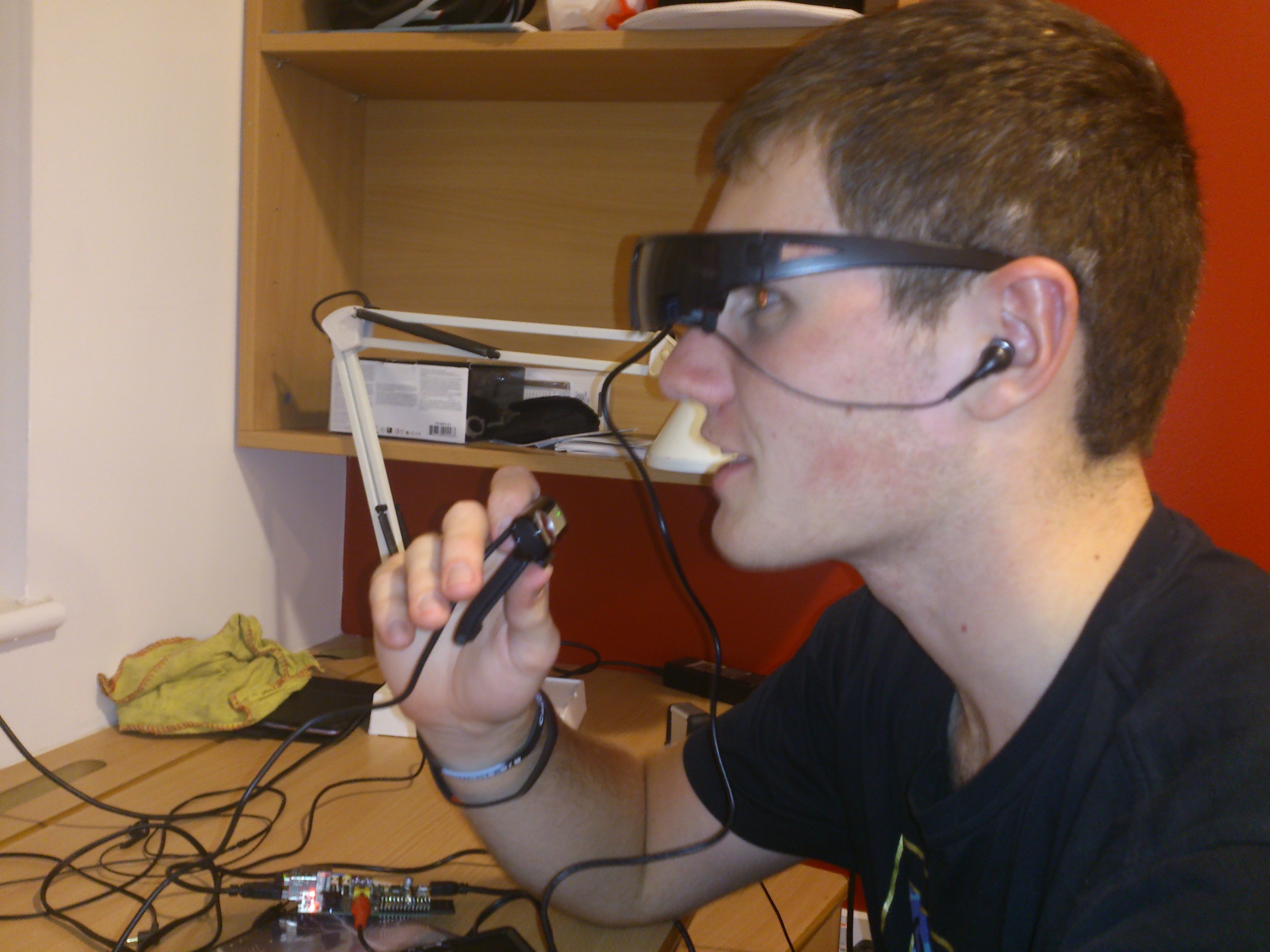
See the video below for our progress so far:
The beginning:
As we are just starting out any feedback or suggestions would be greatly appreciated.
Here is our current plans for the project:
Everything controlled via voice commands using Bluetooth microphone
Camera function
Night vision option using IR LEDs
GPS tracker (able to calculate speed/distance etc.)
Integration with fitness devices (e.g. heart rate monitor)
Possibility for linking with smartphones
Possibility for elements of home automation
I’m Dan and I’ll be dealing with the electronics and hardware side of things, my friend Mike will be writing the software for the Raspberry Pi and doing the physics with the lenses and projecting the image.
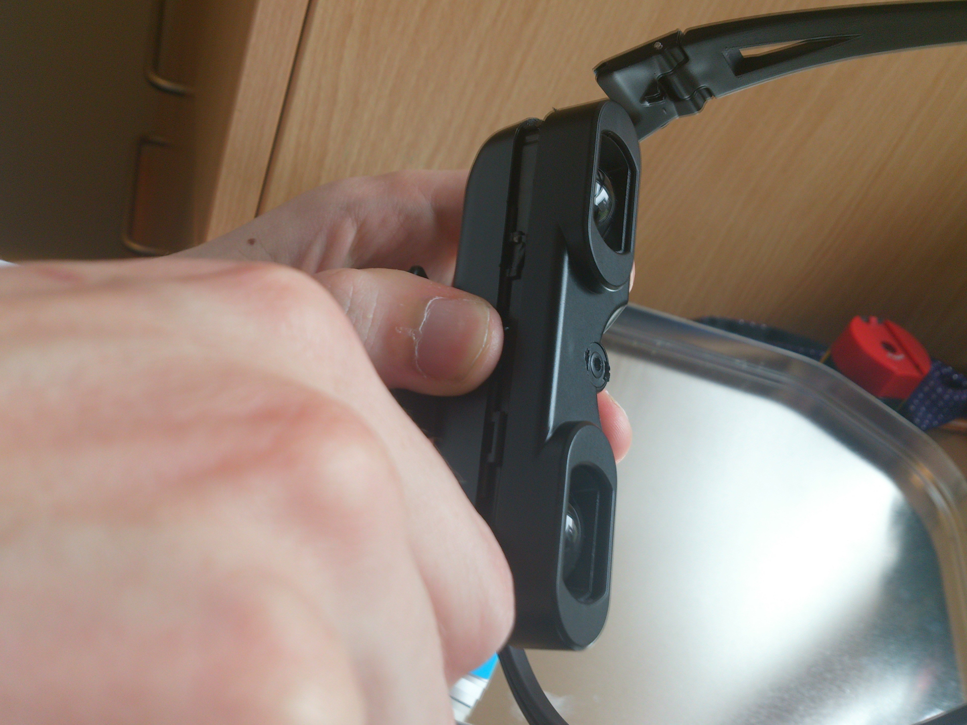
First of all we purchased a £50 pair of video goggles off amazon.co.uk. (edit: they have now gone up in price slightly to £65)
I know that sounds a lot but this will be a massive proportion of the money spent. These have composite video input with dual ear buds for stereo sound. They also include a conveniently small battery pack. Then the fun part came, ripping them apart. After a quick test with a Raspberry Pi, the only thing we had lying around with composite video out, to ensure both screens worked, we started to take them to pieces. This was done by bending the frames slightly to remove the lenses in the sun glasses and then undoing the two screws this revealed. The Health and Safety sticker was then cut with a knife allowing the two halves to separate and to let us have a look at the internal circuitry.
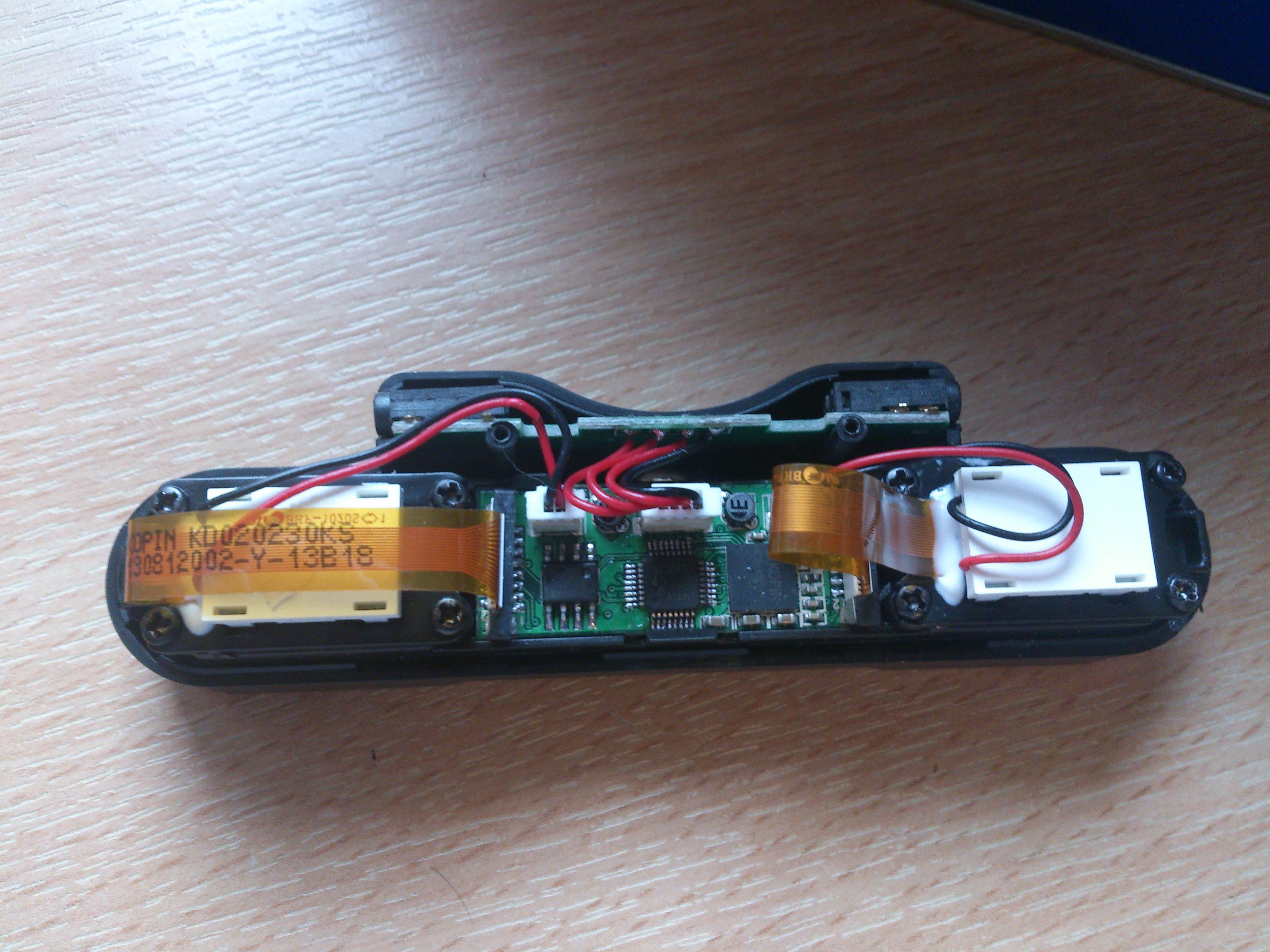
As can be seen, this consists of a breakout board at the top which splits the input into the two audio channels and directs the rest to the display board. This is then connected to the LCDs using a ribbon cable for the data and a two wire connector for power. Following the traces on the breakout board showed that the audio signals were directly connected to the jacks, meaning this board could be replaced with wires and then ignored for the audio signals. As the display board was miniscule, we couldn’t make that any smaller, so we left it as it was.
Shrinking the control board - Part 1
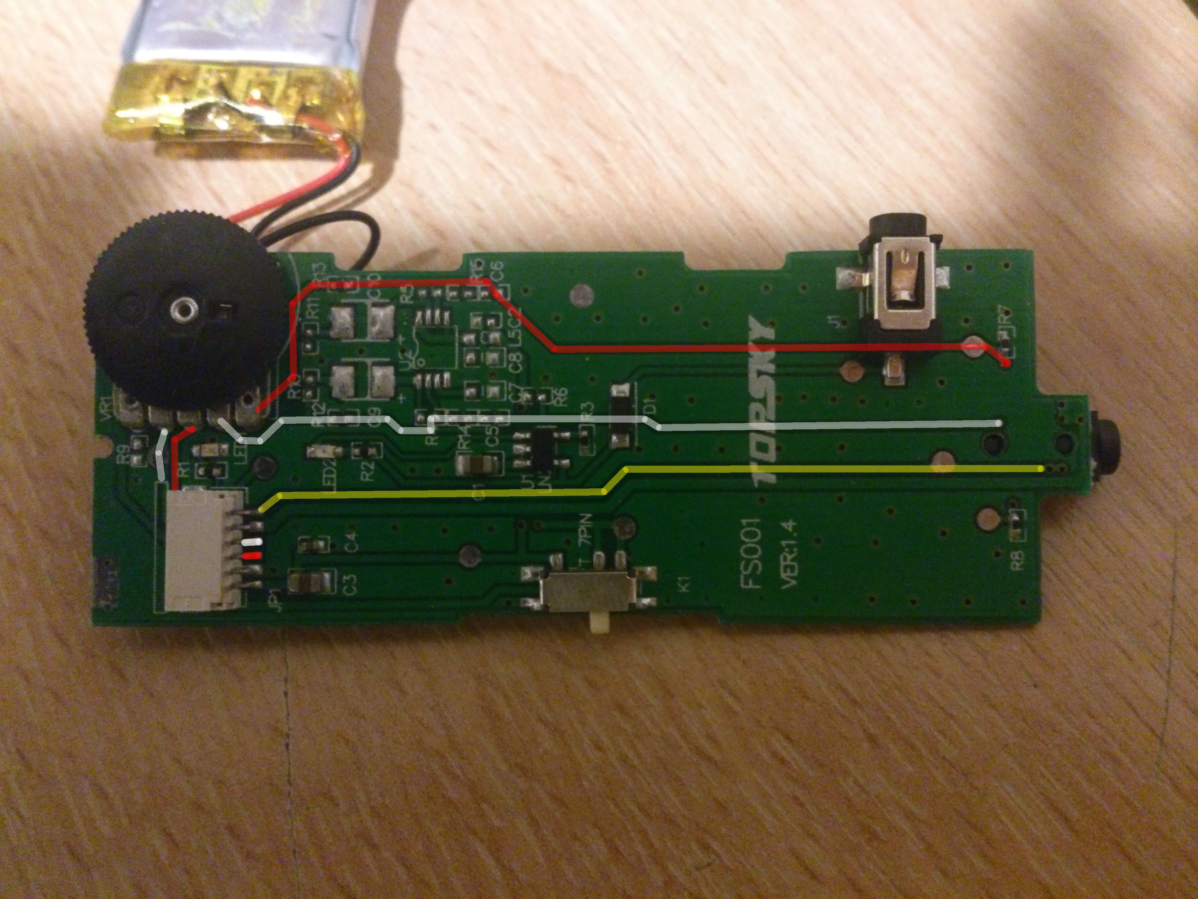
Now we had got a rough idea of how the electronics worked together, I (Dan) started to look at the control board to see if it could be made any smaller. Opening the case (4 screws – 1 in each corner including one under the health and safety sticker) revealed a board mostly populated by....nothing. It was just about empty. Quick testing with a multimeter showed that the video signal passed straight through, the audio signals went through one resistor and then a variable resistor functioning as a volume control and all 12 components on the board were a charging circuit for the battery.
![]()
Yellow Shows the video going straight through
Red and white are the two audio lines
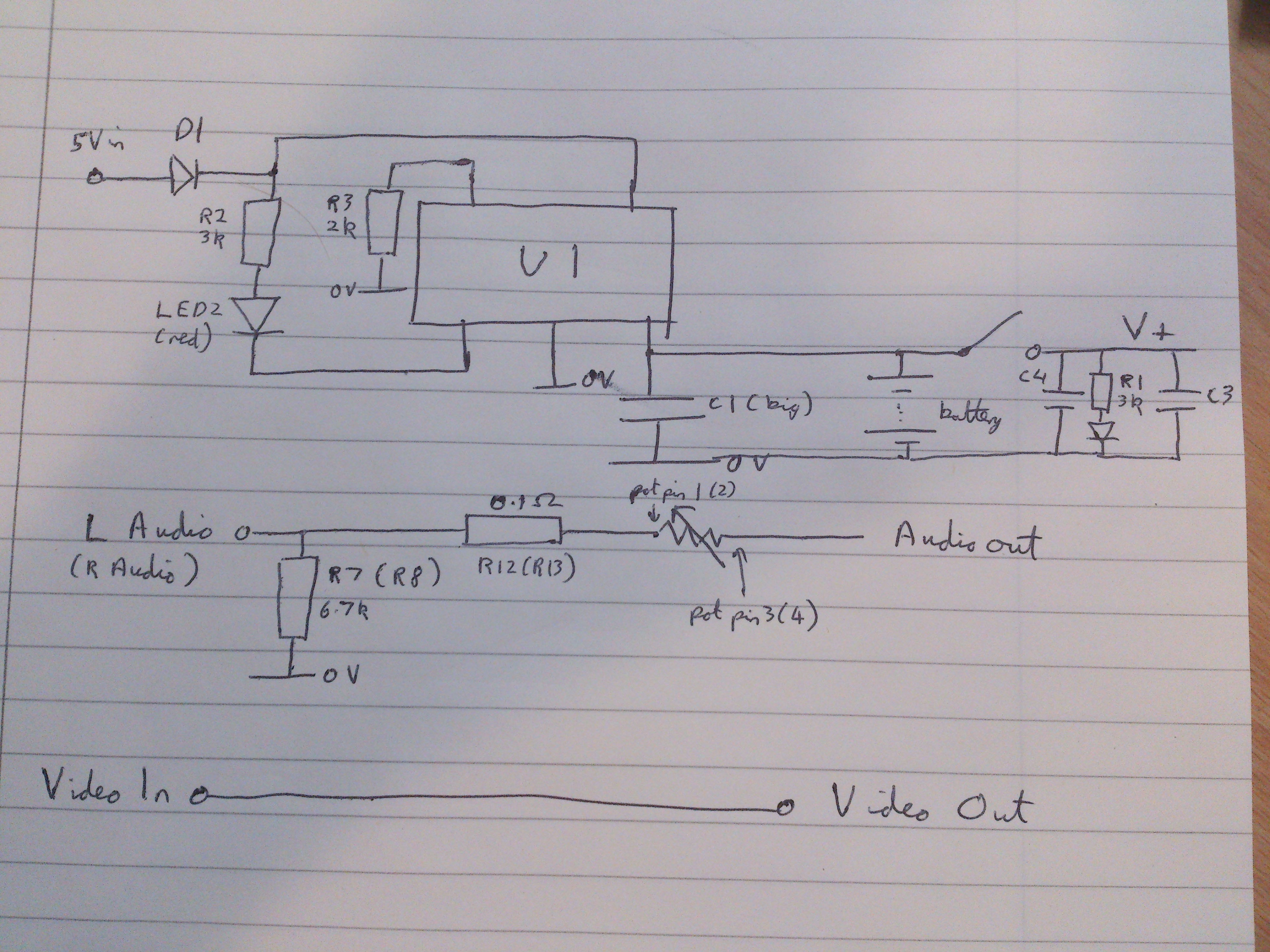
I sat down and, using only a multimeter with continuity test, managed to create a circuit diagram for the board. From this, I will be able to rebuild the board much smaller as it only needs to have 12 components on it. This micro surgery may be a little ambitious for some but should be no problem for people with experience with a soldering iron and a good magnifying glass. The simplicity of the circuit is shown in the circuit diagram and tomorrow, I’ll see what I can do to shrink this board and see how small we can go.
![]()
As we are uncertain as to what U1 is, the physical layout is used in the circuit diagram. As both audio paths are identical, the circuit is only shown once with the values in brackets referring to the other line.
-
Speech Recognition - Part 1
Other than the hardware, the other main aspect to this project is the software and user interface. I am going to be working with the raspberry pi with the Debian “Wheezy” OS installed and doing most of the programming via SSH.
The first thing that I started to work on in this respect was voice recognition as this would be crucial to our design, mainly because the user will have no other way of inputting information. Having looked around I decided that CMU sphinx’s tool pocketsphinx would be ideal as it is quite light weight and designed for embedded systems. The next step was have some way of recording sound to the raspberry pi and for this I decided to use a USB webcam as not only does this have an integrated microphone, there is also a small camera which we may wish to implement in the future.
With this all set up it was time to test out the software to see how accurate it was. For the most part I was impressed by the results with the phrase “good morning” being recognised almost instantaneously.
![]()
Despite this when sentences became longer or certain words were test accuracy fell of greatly. I think that this is mainly due to the language model being used being American English while my partner and I are British. This was especially apparent with words such as aluminium which have very different pronunciations on the two dialects.
To improve accuracy I have two options. The first is to change the language model to a British one to account for the change in accent and the second is to limit the dictionary so that it only looks for the words we want, so for example if we say “computer” it will not return “commuter”. -
Video Upload - Part 1
Here is a quick video showing what we have done so far.
