This project is currently aimed at extracting an absolute XY coordinates from a 2D gray code at up to 60Hz. This should be fast enough for a PID XY control.
To make the experience fit your profile, pick a username and tell us what interests you.
We found and based on your interests.
This project is currently aimed at extracting an absolute XY coordinates from a 2D gray code at up to 60Hz. This should be fast enough for a PID XY control.

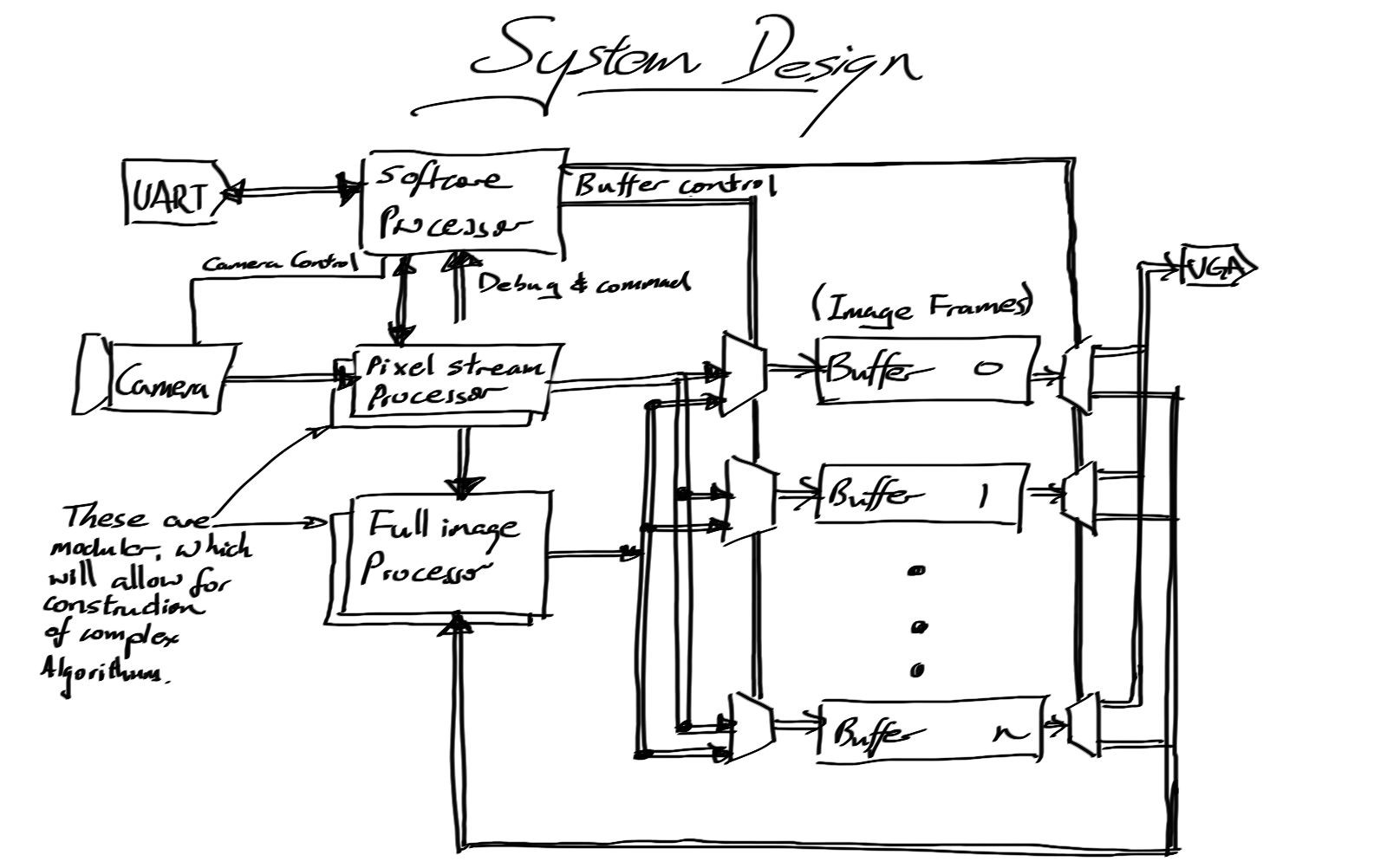
Once the 12bit color was implemented, the next step was to add more memory, so that the processor can do some useful work. But it turns out the easy to use SPI memory provided only bottlenecks. With a maximum of 80Mbits / second transfer rate, it would be faster to do any planned processing on a computer with webcams. This has steered the project to the inevitable end of custom hardware, which I was hoping to avoid. Never-the-less, the aim to make it to a budget still remains. So, expect hardware updates to come...
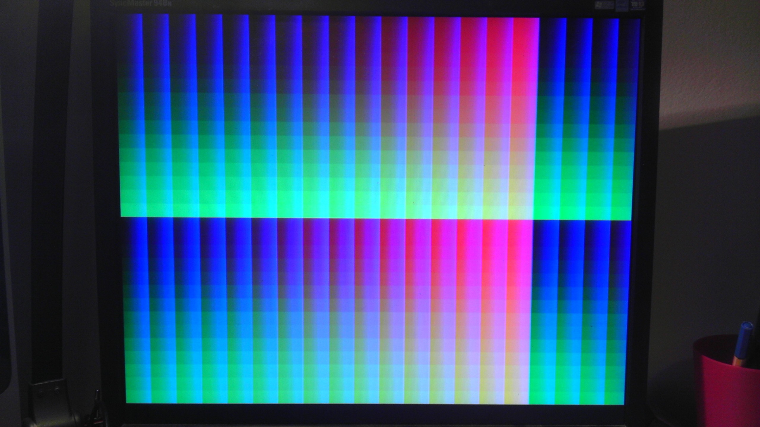
Just having 3 bit color was quite boring, so with the help of a 'few' resistors I now have 12 bit color (444RGB). The DAC is made up of a 4 bit R2R network with R = 33ohms.
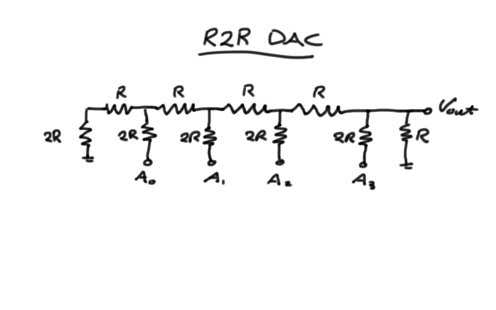
Three of these are used, one for each of the RGB channels to the VGA output. The final R at the output is to divide the output to be within 0.7V, which if full brightness.
One main issue was the auto DC voltage removal by the monitor. This was caused by the DAC not outputting 0V during sync signals. It worked perfectly once the sync pulses where used to mask out the video output.
Next step is to add more memory to the system. The memory of choice is a 4bit serial 1024kb memory. The plan is to add two or three, allowing a circular buffer. The 4 bit communication also matches the color depth of each channel for convenience. Hopefully once the memory is in, it can be tested with the Conway's game of life.
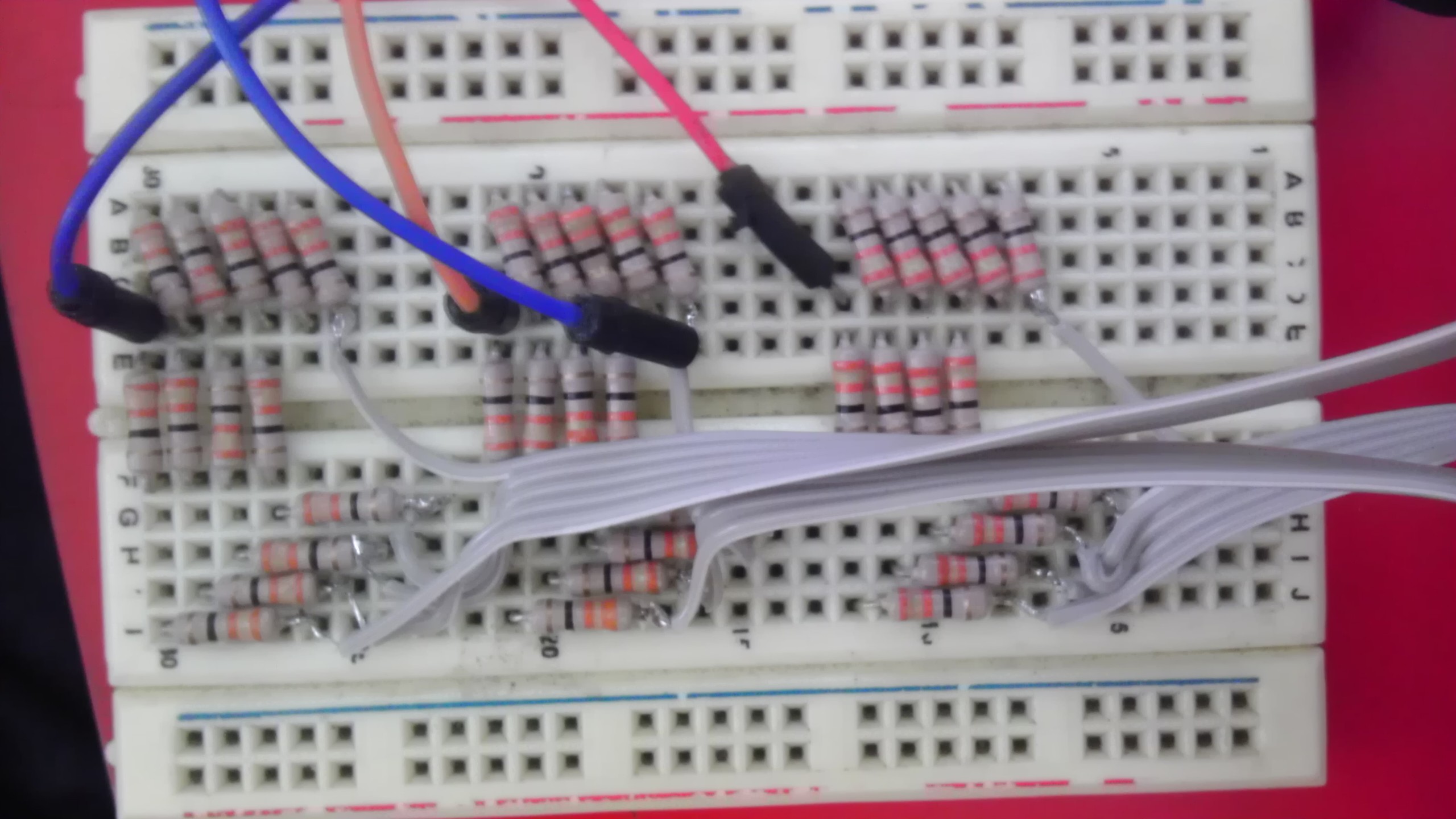
And just ending this log with a photo of the R2R network on breadboard :) I chose to solder the wires directly to the resistors as I was running low on headers.
The FPGA can see!
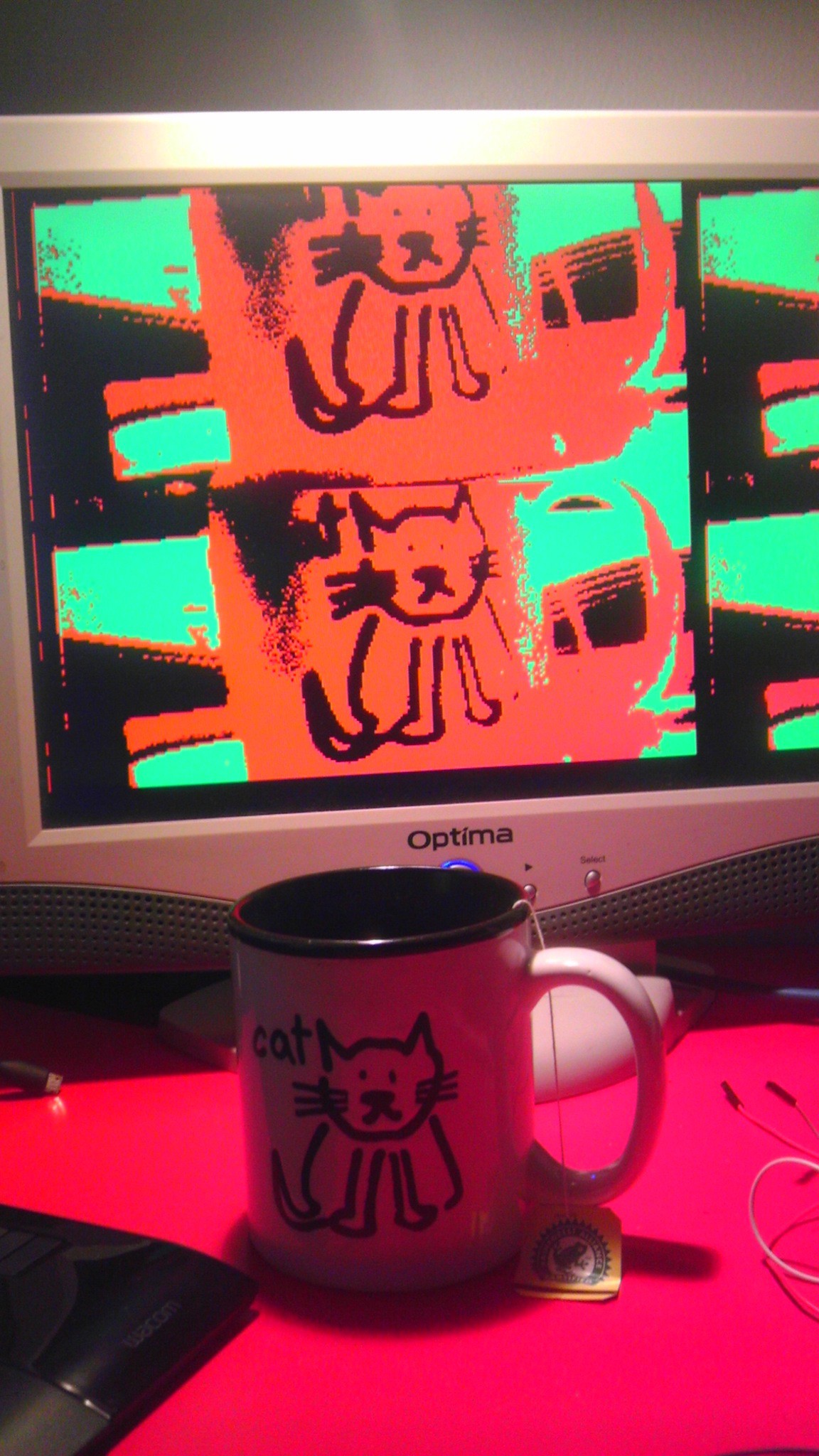
The camera is an OV7670 which has a 600x800 resolution. The image stored on the FPGA has been reduced down to 1/4 size and only 3bits per pixel. This was done to reduce memory. The aspect ratio on the photo is off. That was due to the use of a memory block with power of 2 size. When the aspect ratio was fixed, there is unused memory which I plan to have region of interest (ROI) where I will place a cropped full 1x size region. This will allow effective pattern identification and also high resolution position tracking.
VGA WORKS! We have output.
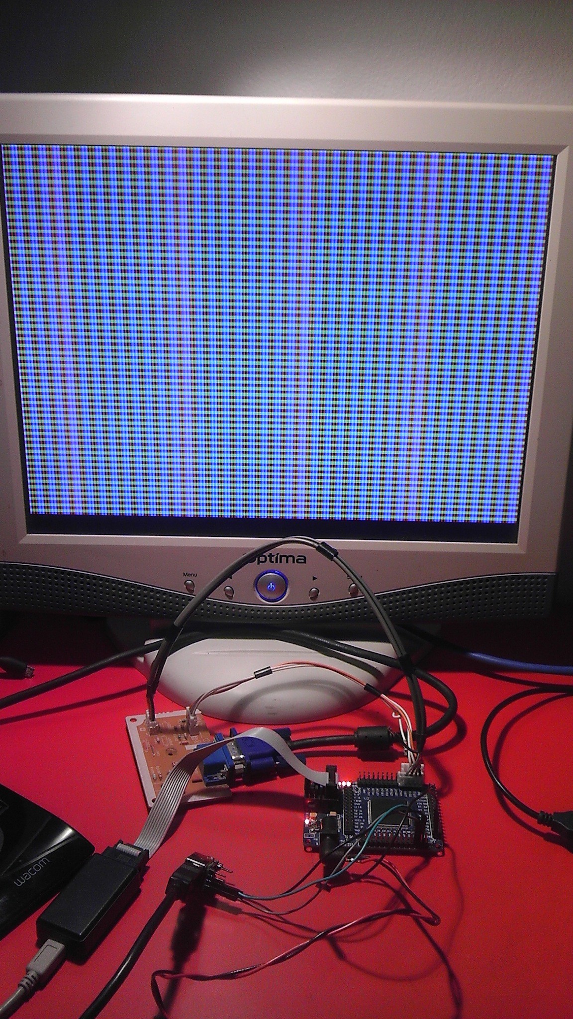 Next step, camera to screen loopback. Then the fun begins.
Currently the VGA is generated by counters for HSYNC and VSYNC. Then video front and back porch are derived from the counters. This keeps everythign nicely in sync. The pattern is generated by masking X-Y pixels with the different bits of the counters. Currently only 1 bit per color hence only 8 colors. Looking to improve that ASAP.
There is a link from computer to FPGA. Now the fun begins.
The current setup uses two ring buffers, one on FPGA and one on computer. Data between the two rings are swapped byte by byte essentially forming one big ring. This interface simplifies the communication as the FPGA is piggy backing off the timing from the computer, but does not allow the FPGA to initiate communication. Might modify this in the future.
Setup git repo. Now one can follow dev.
Meanwhile still trying to get the timing on RS232 recieve to work.
Before any dev is to happen, one must be able to debug. The only IO I have is an LED and a button. I am currently working to add serial and VGA. This should speed up future developments.
Create an account to leave a comment. Already have an account? Log In.
You mention a 2D Gray Code, but in the video I'm seeing a simple checkerboard pattern. Am I missing something or have you not gotten to the actual Gray Code pattern yet?
Where do I find the schematics for this fpga board? which input do I insert the jtag? what's the another input for? Many thanks.
Hi,
That's a nice project. I just read that your problem is the memory and I had to say that I had the same problem before and to overcome this, I used embedded RAM to store just the data necessary for the image processing kernels I had to use (for exemple, for a 3x3 erosion you just need 3 lines).
Actually, I had this project a while ago and because of sensor connectivity problems and time before a deadline, I had to move to a fallback solution. However, you will find the code I did there: https://code.google.com/p/cameramea/source/browse/#svn%2Ftrunk%2FVHDL%2Fcamera%2Fsrc
You will also find the tests. Fill free to use this... if you find something interesting.
Bye
Thanks for the tip, I'll give it a go.. Things have been a bit busy lately so...
My name is Dimitar Tomov and I'm an Embedded Developer. For a long time I wanted to start with FPGAs, etc ...., but You now - there're priorities + things at which you are already good at, which leads to going forward, forward. But there's a point where You have to check if that forward is the Only one You want to walk.
I think I can give you some, if not proper support on developing the project. I offer my assistance - help, knowledge, skills, even ideas, why not - open is best way for People & Ideas, i.e Dreams :-)
+ I'm B.Eng in Automation
+I specialized in Systems And Control:
++ which is Regulators (PID,Neuron Networks,etc)
++ DSP, whatever you can think of:
+++ from FFT through Digital Filtering to Image Processing
--- but I have to admit I'm good at Signals, not Images
___ Get Image to Signal - bits or other, I can continue from there
+ Have great experience with embedded systems and especially bare-metal firmware
++ Bare-metal Drivers for Core, Peripheral, Interrupts , etc ...
++ Bare-metal Communications - from Serial through Parallel to Ethernet, etc based
++ I have so many project behind me now, that I'm starting to forget them
I'm telling you this, cause there might be a skill I have or experience I had that this Project can use,
but I may not remember it so ... Please ask if you seek specific skill or knowledge
+ Also with every day getting stronger Embedded Linux Kernel Development
In one word: Do You want support :D ?
Oh, I use mainly STM32 for bare-metal projects, most of them are F4/DSP based.
My Linux Projects are based on (almost) everything, literally everything - last I was working on Haswell-EP Embedded project.
Excuse me for the long post, but I think - better informative, than short and Uninformative.
Fastest way to contact me is on my Twitter OR E-mail ( dimitar @ _the_site_in_my_hackaday_profile_ ) .
Thank You for Your Time. Good Luck with the project and Be Well :-)
Hi, automation is the high level goal I'm aiming with this project! This will hopefully one day provide feedback in a vision based control loop for a generic CNC system.
The hardware has hit a bottle neck at the moment but once it is all resolved, your experience in control will be very helpful.
Support is always welcomed, so yes :)
ОК. In one word: I can EXPECT to be contacted by You for the Project.
At some point in the near Future - Few months ? Or more distant - half or whole year ?
Best Regards :-)
Hey, this is really interesting! Could you kindly tell me which FPGA are you using? And somewhere to learn from?
It's a low end Altera Cyclone II EP2C5T144C8N. I did a uni course on it.
Become a member to follow this project and never miss any updates
 Xark
Xark
 Dylan Brophy
 Santiago Germino
Hey, can you share me the links to the modules you used with the fpga board... and how easy is it to interface with the modules?