 JLAM
JLAM-
Bottle necks :(
01/23/2015 at 11:18 • 0 commentsOnce the 12bit color was implemented, the next step was to add more memory, so that the processor can do some useful work. But it turns out the easy to use SPI memory provided only bottlenecks. With a maximum of 80Mbits / second transfer rate, it would be faster to do any planned processing on a computer with webcams. This has steered the project to the inevitable end of custom hardware, which I was hoping to avoid. Never-the-less, the aim to make it to a budget still remains. So, expect hardware updates to come...
-
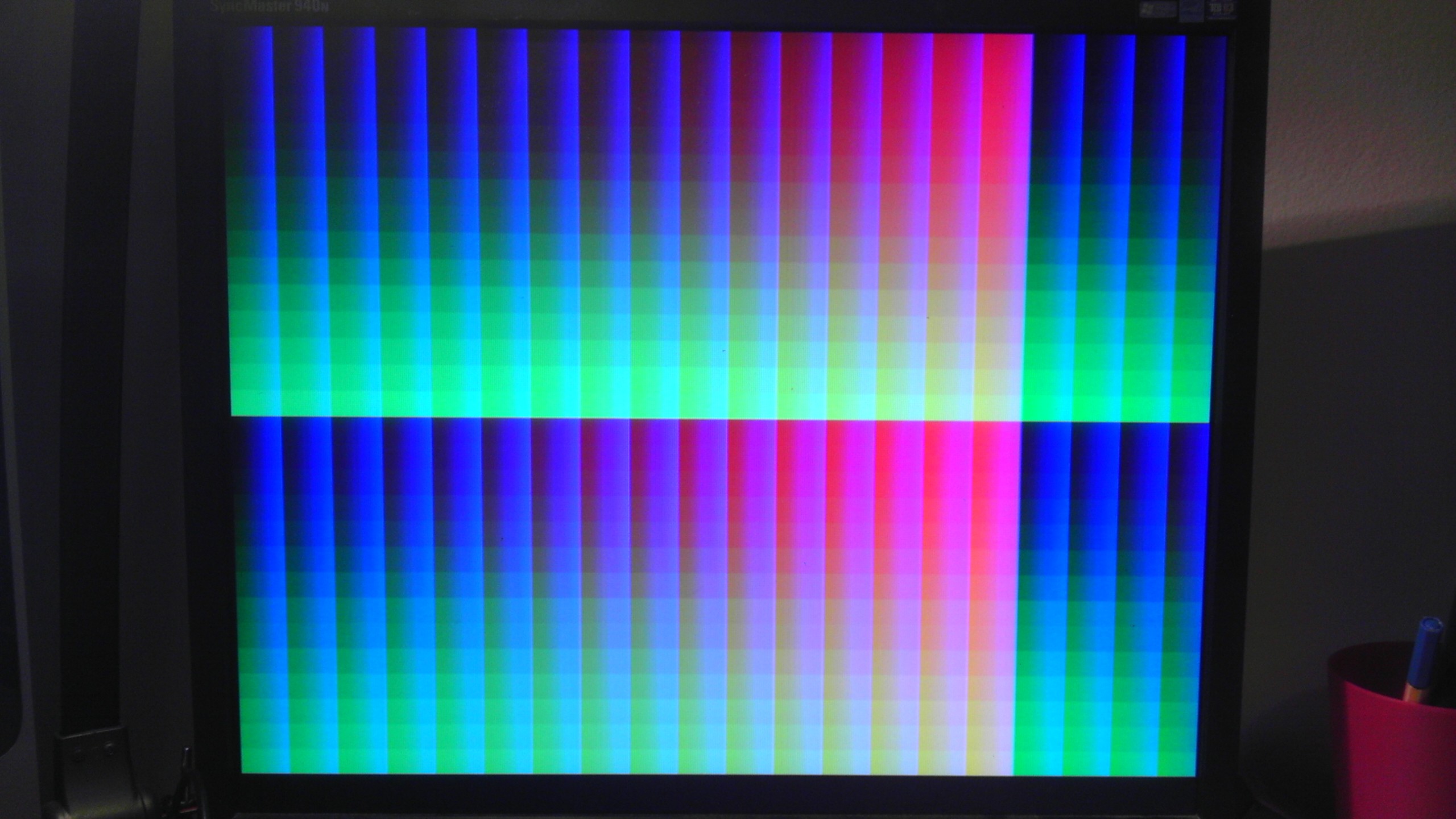
12 bit color
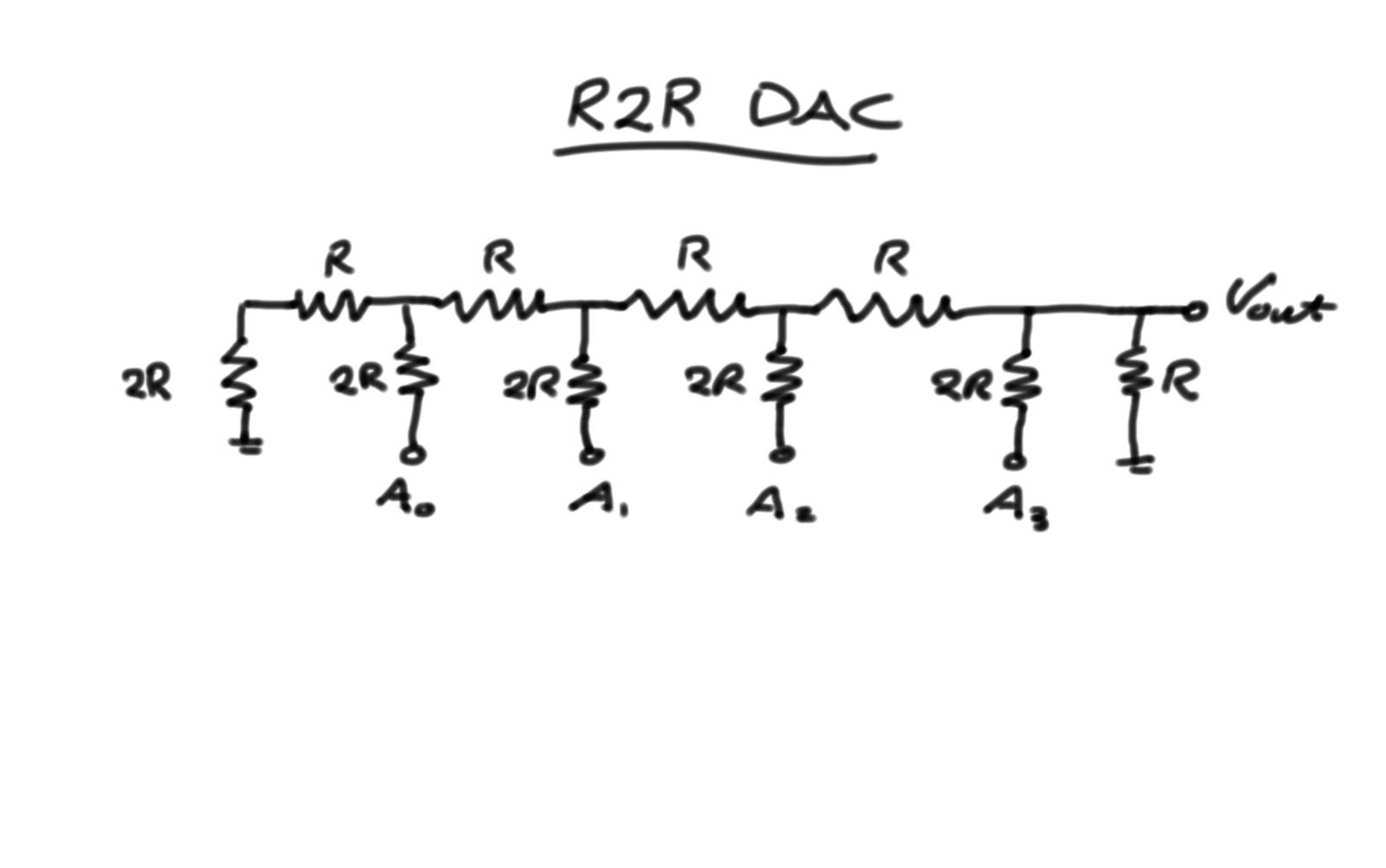
01/18/2015 at 12:57 • 0 commentsJust having 3 bit color was quite boring, so with the help of a 'few' resistors I now have 12 bit color (444RGB). The DAC is made up of a 4 bit R2R network with R = 33ohms.
![]()
Three of these are used, one for each of the RGB channels to the VGA output. The final R at the output is to divide the output to be within 0.7V, which if full brightness.
One main issue was the auto DC voltage removal by the monitor. This was caused by the DAC not outputting 0V during sync signals. It worked perfectly once the sync pulses where used to mask out the video output.
![]()
Next step is to add more memory to the system. The memory of choice is a 4bit serial 1024kb memory. The plan is to add two or three, allowing a circular buffer. The 4 bit communication also matches the color depth of each channel for convenience. Hopefully once the memory is in, it can be tested with the Conway's game of life.
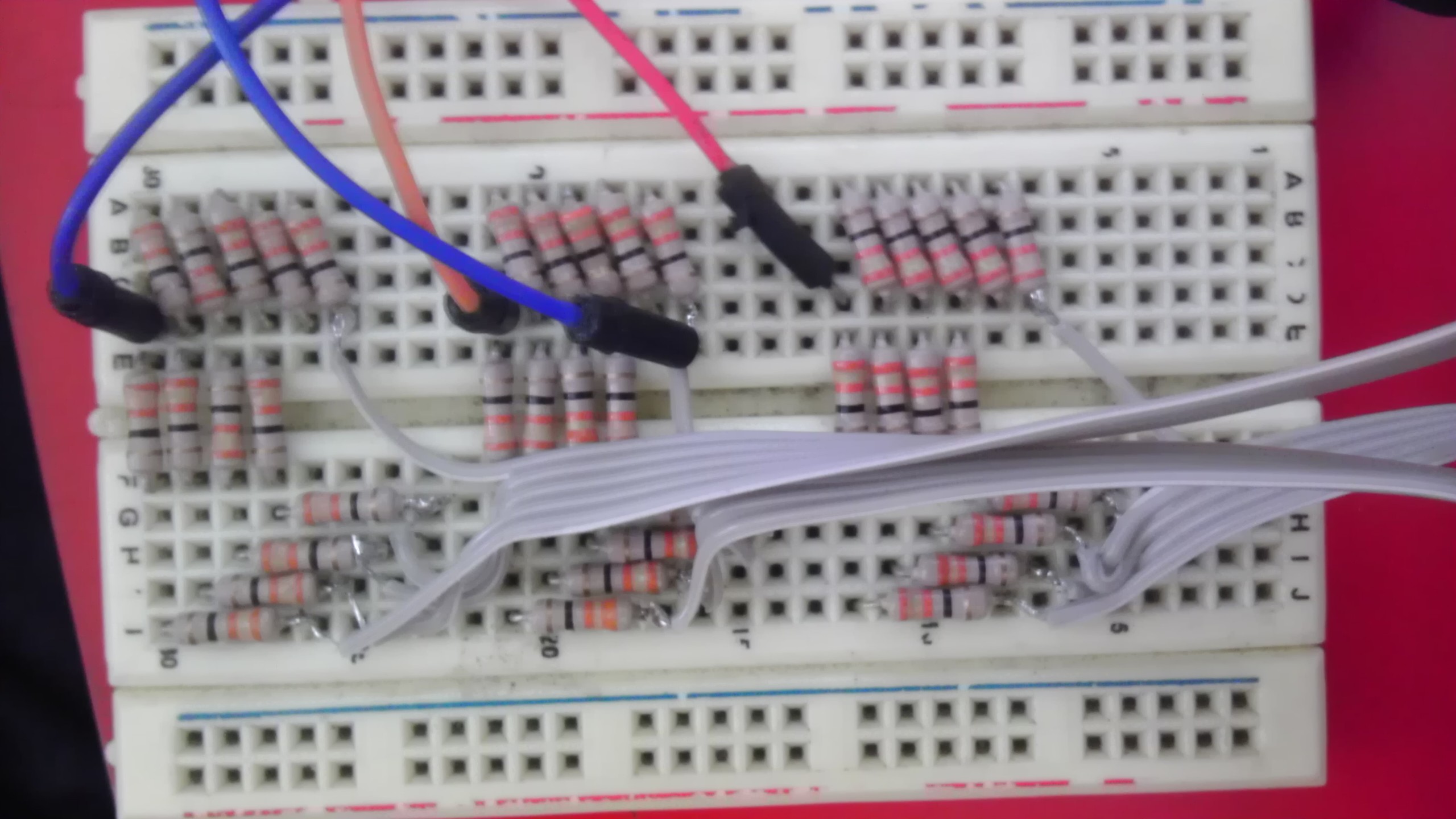
And just ending this log with a photo of the R2R network on breadboard :) I chose to solder the wires directly to the resistors as I was running low on headers.
![]()
-
I spy
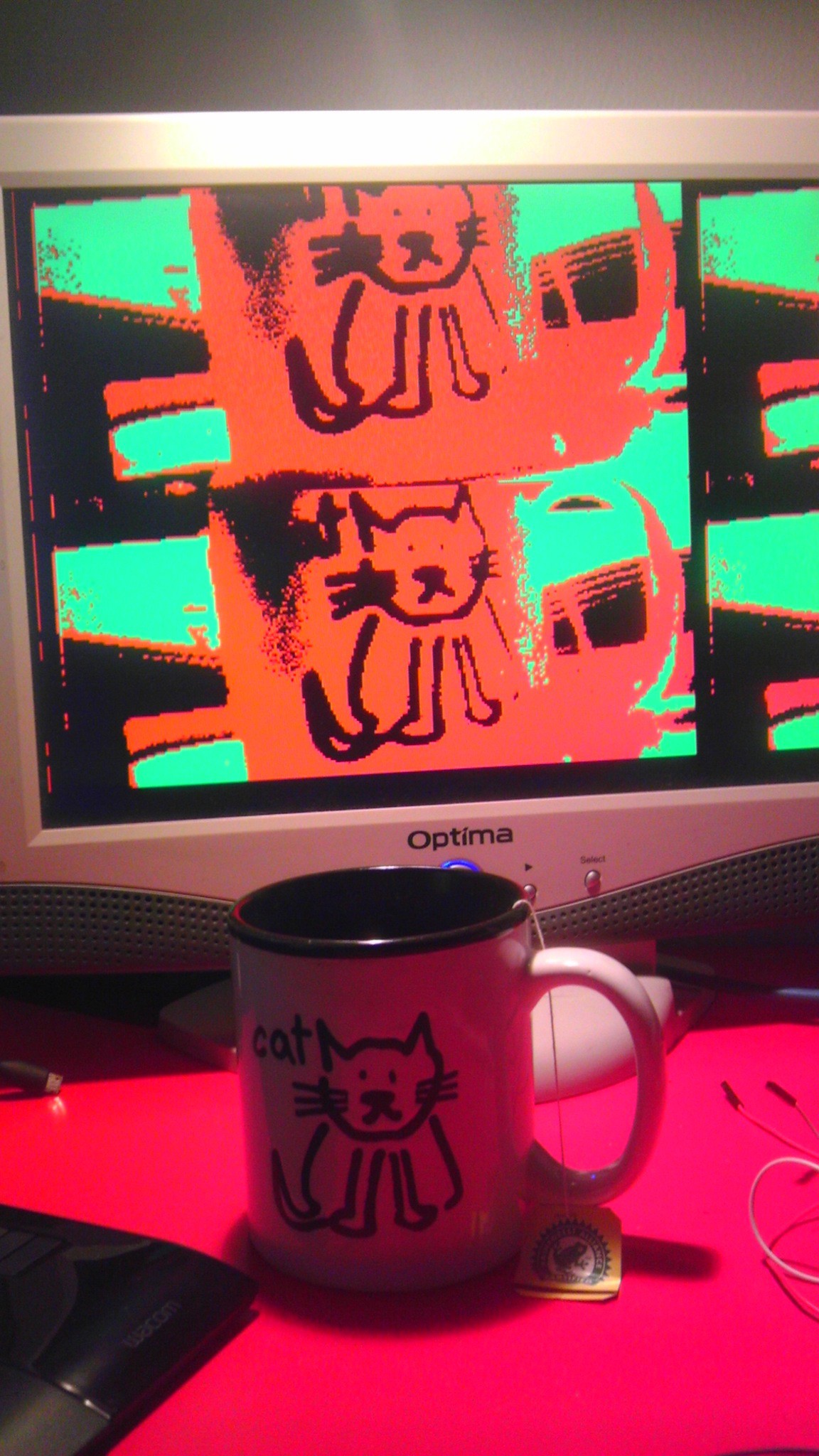
07/10/2014 at 12:28 • 0 commentsThe FPGA can see!
![]()
The camera is an OV7670 which has a 600x800 resolution. The image stored on the FPGA has been reduced down to 1/4 size and only 3bits per pixel. This was done to reduce memory. The aspect ratio on the photo is off. That was due to the use of a memory block with power of 2 size. When the aspect ratio was fixed, there is unused memory which I plan to have region of interest (ROI) where I will place a cropped full 1x size region. This will allow effective pattern identification and also high resolution position tracking.
-
First light
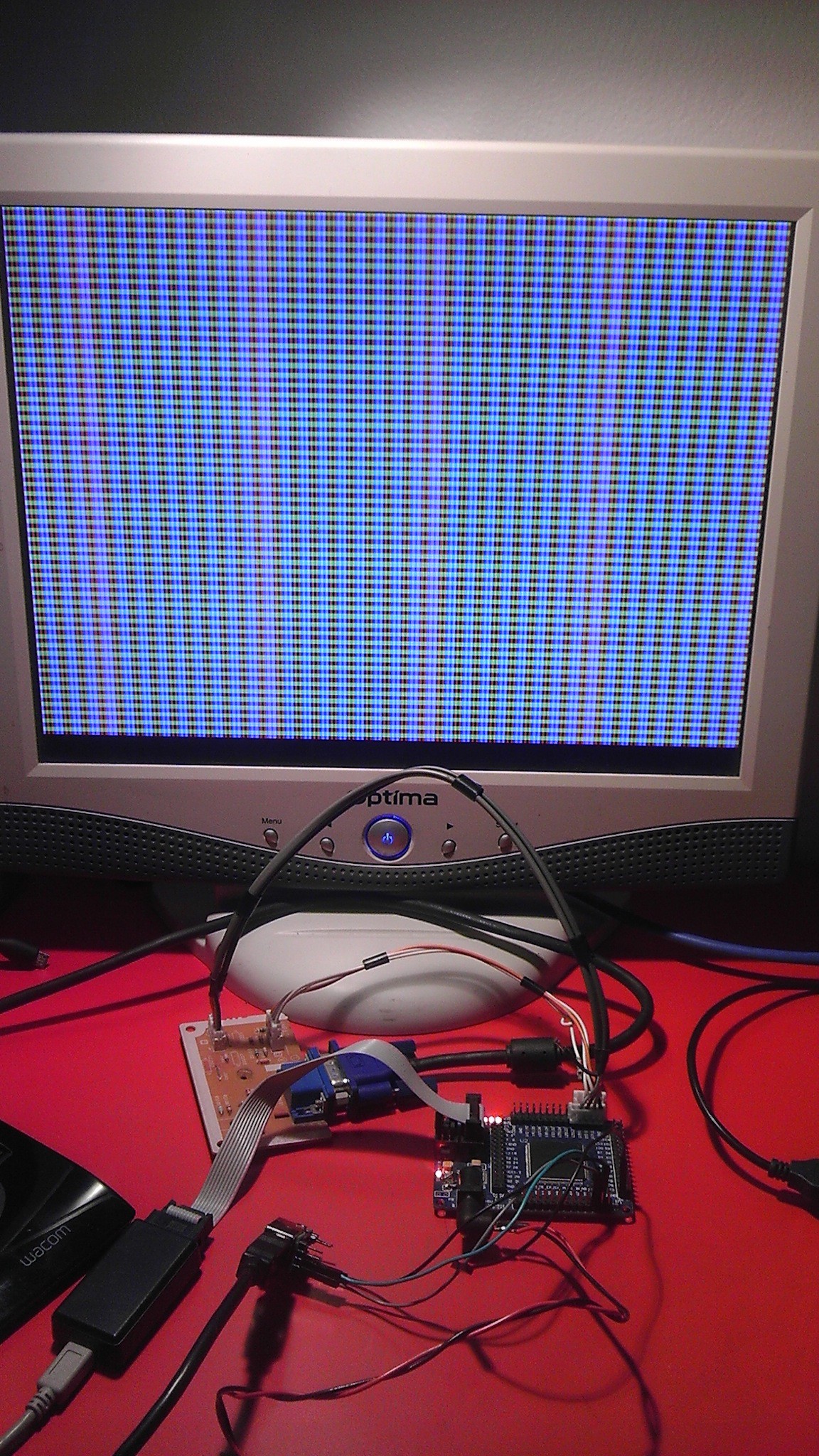
07/04/2014 at 15:48 • 0 commentsVGA WORKS! We have output.
![]() Next step, camera to screen loopback. Then the fun begins.
Next step, camera to screen loopback. Then the fun begins.Currently the VGA is generated by counters for HSYNC and VSYNC. Then video front and back porch are derived from the counters. This keeps everythign nicely in sync. The pattern is generated by masking X-Y pixels with the different bits of the counters. Currently only 1 bit per color hence only 8 colors. Looking to improve that ASAP.
-
UART works
07/03/2014 at 14:33 • 0 commentsThere is a link from computer to FPGA. Now the fun begins.
The current setup uses two ring buffers, one on FPGA and one on computer. Data between the two rings are swapped byte by byte essentially forming one big ring. This interface simplifies the communication as the FPGA is piggy backing off the timing from the computer, but does not allow the FPGA to initiate communication. Might modify this in the future.
-
Source.
07/01/2014 at 00:52 • 0 commentsSetup git repo. Now one can follow dev.
Meanwhile still trying to get the timing on RS232 recieve to work.
-
One small step.
06/29/2014 at 13:46 • 0 commentsBefore any dev is to happen, one must be able to debug. The only IO I have is an LED and a button. I am currently working to add serial and VGA. This should speed up future developments.
 Next step, camera to screen loopback. Then the fun begins.