Bradley Worley
-
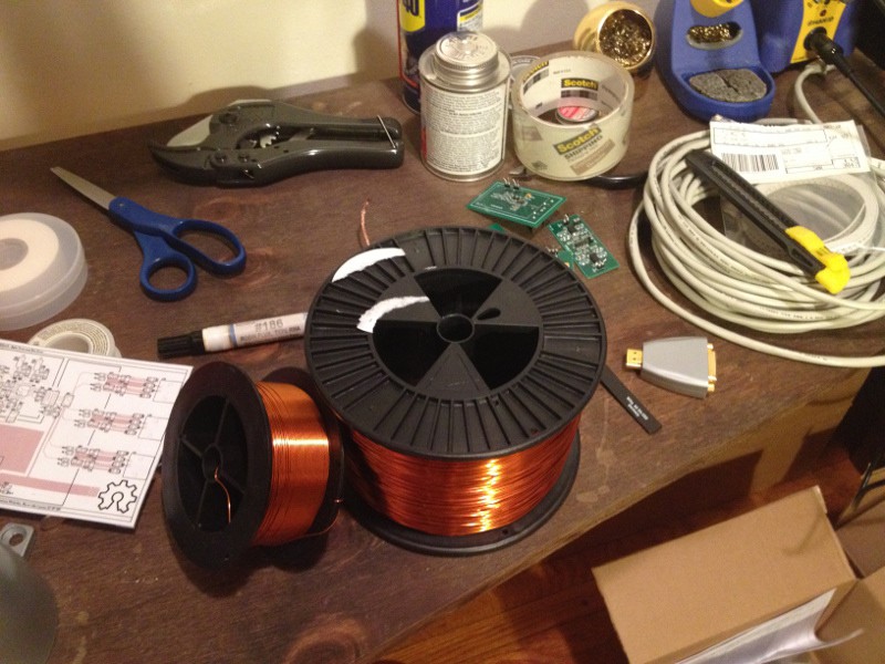
Ready to wind some coils
06/19/2014 at 13:19 • 0 commentsI just got the magnet wire I ordered in the mail, and I'm waiting on the shim control boards now.
![]()
Properly winding the humbucking sensor coil pair requires matching the inductances of the two counter-wound coils to a reasonable level of precision. I decided to use the PyPPM hardware as an advantage here: I wrote a small OpenGL program to hook into the core PyPPM C API and continuously read out samples from the analog signal chain to produce a live-updating spectrum.
You can see a quick demonstration video below.
The result is pretty cool, and I can use the software (called 'liveft' in the PPM sources tarball) to check inductance matching while I wind the new coils. Ideally, when the coils are well-matched, any common-mode interference that would be picked up by a single-ended coil will be minimized.
-
The first PyPPM shim driver board!
06/16/2014 at 02:43 • 0 commentsWhat an eventful weekend this was! I managed to design a first revision shim control board (SCB) for the PyPPM, which will allow the host computer to manage currents flowing through the three new shim coils (X, Y and Z) to be constructed.
As a reminder, shim coils produce precisely controlled DC magnetic field gradients. The gradients produced by the shim coils are used to counteract the ambient magnetic field inhomogeneity. The simplest set of shims consists of three linear field gradients: one along X, one along Y, and one along Z. This board will control all three.
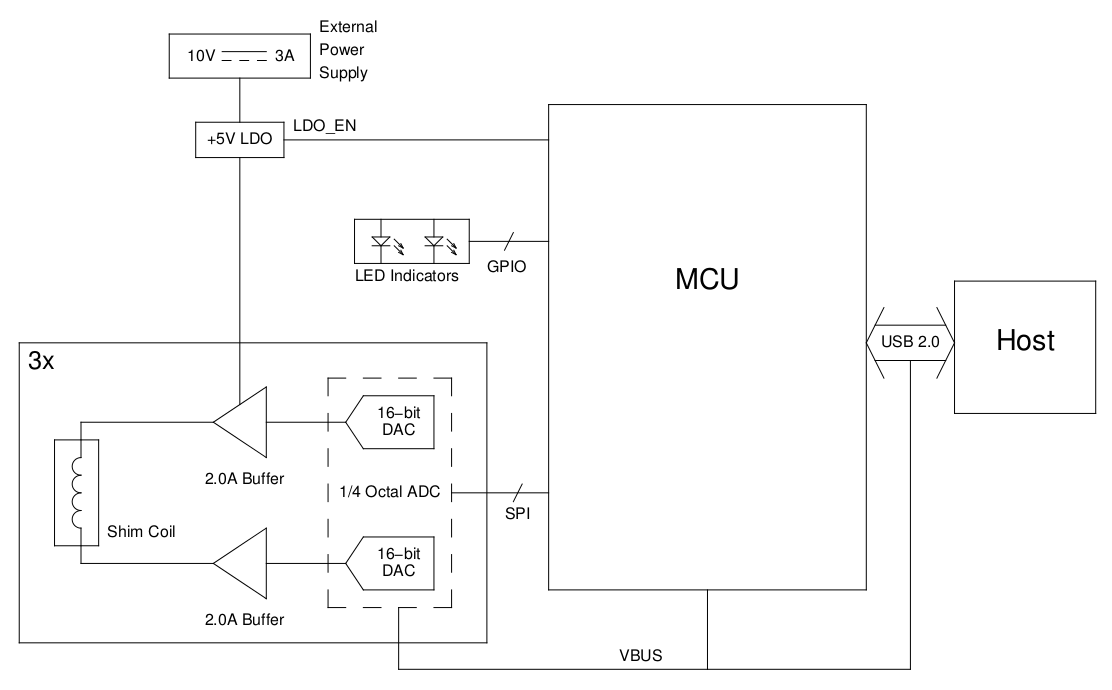
The design: In a nutshell, the SCB takes three 17-bit (16 bits, plus a sign) digital words, one for each DAC output code. The DAC voltage outputs are buffered into the shim coils in a bridge-tied load configuration, with one pair of DAC outputs per coil.
![]()
(Note: the "2.0 A buffer" is a remnant from an earlier design decision that had to be reversed. The actual current capacity of each buffer is a mere 320 mA... Newer versions of the SCB will undoubtedly have greater current handling capability than this first revision)
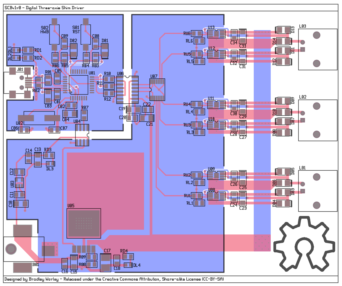
The boards: I decided to cram everything into the same Hammond case as before, which wasn't too much of an ordeal. I had to downgrade from OPA569 (Io < 2A) to TLV4110 (Io < 320 mA) output opamps due to the size constraints, a decision that will surely keep me awake at night tonight. :P
![]()
The MSOP8 packages (with exposed pads!) are going to be fun to solder...
-
More hardware documentation
06/14/2014 at 16:03 • 0 commentsI finally got around to documenting the sensor coils and the case millwork! It's the small things in life that matter, or that's what I told myself. :)
The coil (rev 1.0). The relevant parameters of the coil are now documented in the source tree of the PyPPM project tarball. This nails down the exact design parameters I used. While you could go to the trouble of fabricating coil forms using a 3D printer, it's easiest to use 2" diameter plumbing PVC from a hardware store. Just close off one end, add a screw cap to the other, and wind the wire between the raised edges of the pipe fittings.
![]()
The coil (rev 2.0). My plan to use counter-wound solenoids is finally taking shape. From my estimates, the interaction (during polarization) between the solenoids will be negligible at a 15 cm distance. However, that's only a relevant consideration for the current PPM board, which will have to polarize and observe on both coils in series. Newer versions of the hardware will connect to the coil using a proper three-wire system, which will allow for polarization of a single coil and acquisition through both coils differentially.
![]()
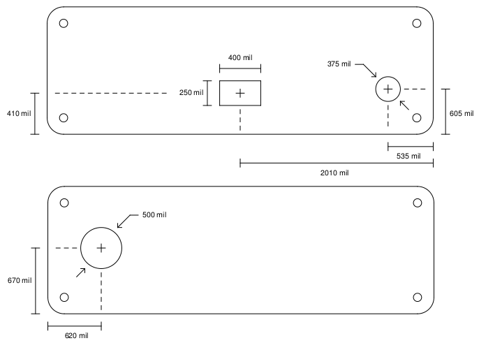
The case. While the dimensions of the case cutouts are completely unexciting, they're still progress:
![]()
More to come on the hardware designs, including an update on the shim driver circuits!
-
Progress with new coil designs
06/10/2014 at 16:30 • 0 commentsIt works, but it's not finished!
One design goal of PyPPM is to host the device on the internet, making it possible for anyone to visit a web page and click to collect a Free Induction Decay of their own. In order for that to become a possibility, a few improvements have to be made to the design:
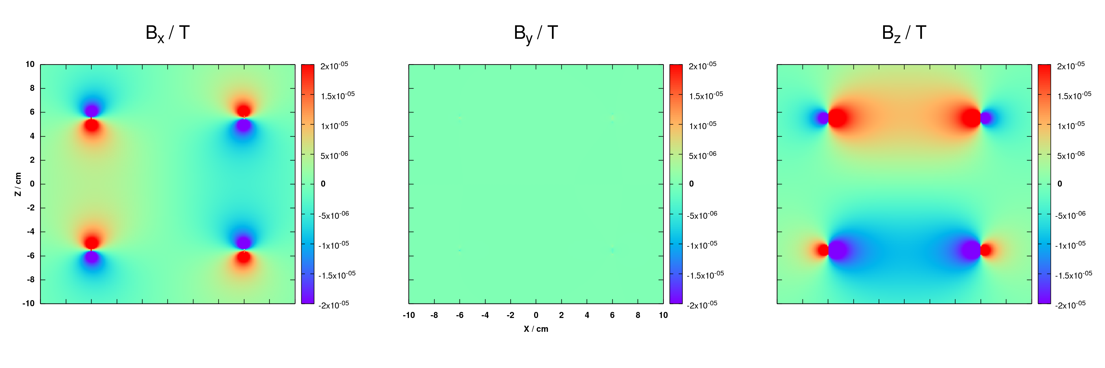
Magnetic field calculations: Designing the new coils for PyPPM required an understanding of the magnetic fields they produce. I wrote a small C program that uses the Biot-Savart equation to compute magnetic fields generated by any geometry of (infinitely narrow) wire.
The software is licensed under the GNU GPL and is freely available here: GPUfield at Geekysuavo.org.
Interference cancellation: Even out in a sub-urban plot of land, the revision 1.0 sensor coil picks up significant interference. In a building, with wires running through the walls and computers kicking out EMI, it's even worse. The worst offenders are high-order harmonics of the 60 Hz mains frequency that fall within the pass-band of the PyPPM analog signal chain.
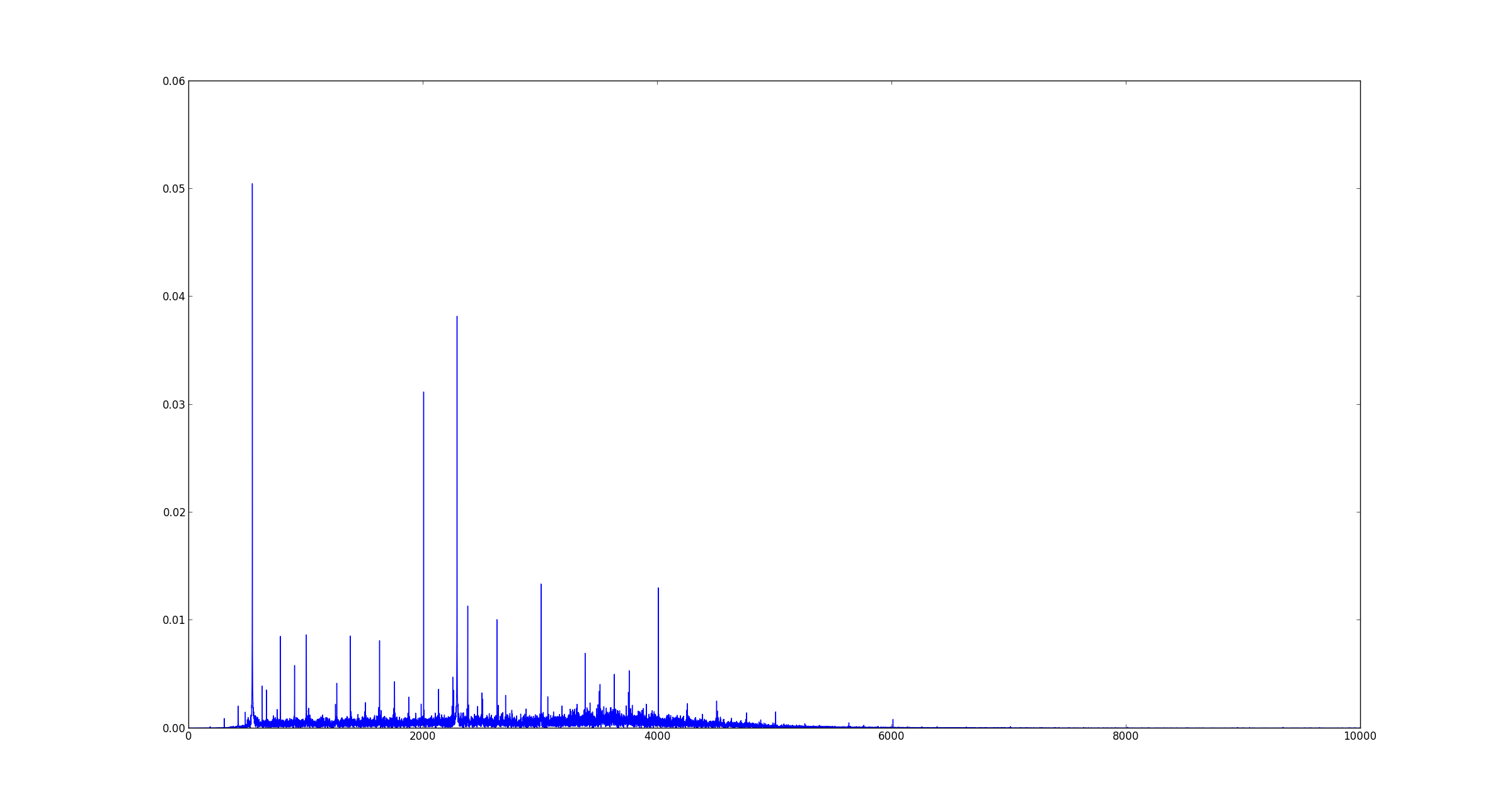
For example, after a single scan (15 seconds of experiment time) in the outdoors, I can get a spectrum that looks like this:
![]()
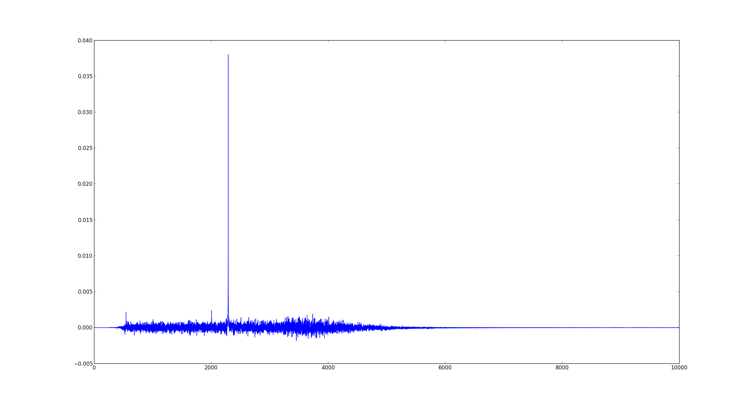
I can also collect a signal of background interference. By finding a scale factor that minimizes the sum of squares of the differences between the two spectra, I can subtract out any stationary interferences and get a spectrum of pure NMR signal:
![]()
While this works great in the frequency domain, there's no easy way to get back to the filtered time-domain signal using this method. So, you wouldn't be able to hear your NMR signal through the computer speakers. :(
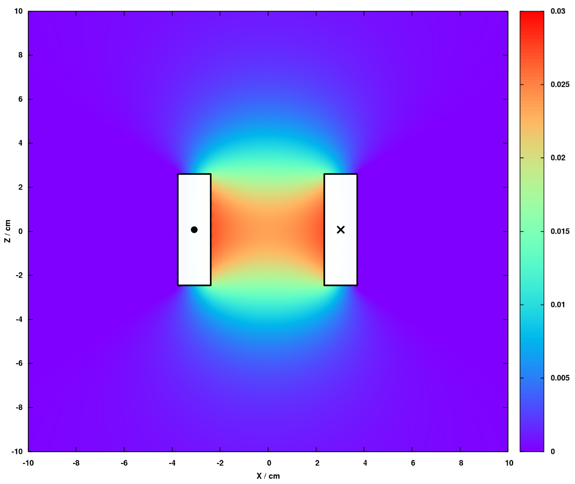
A better way to remove interference is at the source, using a hum-bucking coil arrangement. The new design will feature two counter-wound coils, aligned to the same vector, and spaced a few centimeters apart. The sample will only be placed in one coil, which causes the differential voltage between the coils to be just the NMR signal.
Field calculations of the new coils are underway to get an estimate of inductance and coupling versus various arrangements. A slice through one of the new coils shows improved field strength over the previous design:
![]()
A few final details... Per coil gauge: 18 AWG, inner diameter: 5 cm, length: 5 cm, turns per layer: 50, layers: 15. Estimated single-coil inductance: 14.5 mH, resistance: 3.5 Ohms.
I should be able to start building these coils soon.
Inhomogeneity correction: Running experiments indoors inherently means dealing with inhomogeneous ambient magnetic fields. Structural iron, or even the right kind of furniture, can distort the Earth's magnetic field lines enough to blur an NMR signal.
An example is apparent in the first signal captured by the PyPPM (see the previous log). The signal at 1775 Hz corresponds to a 41 microTesla (uT) field, and the 60 Hz signal width indicates a mere 1.4 uT field inhomogeneity inside the 10 cm x 5 cm solenoid.
To make the field around the new coils more homogeneous, I plan to build a set of coils called a "shim stack". At the very least, I will design a Z-shim that removes any linear field gradient along the Z-axis:
![]()
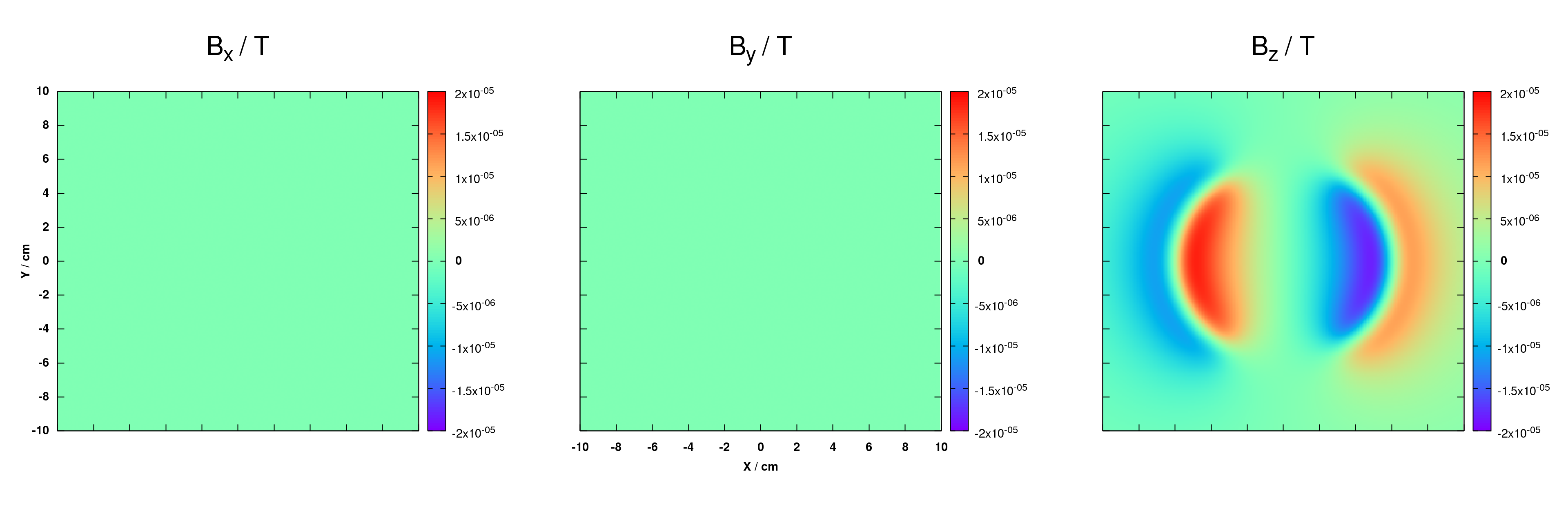
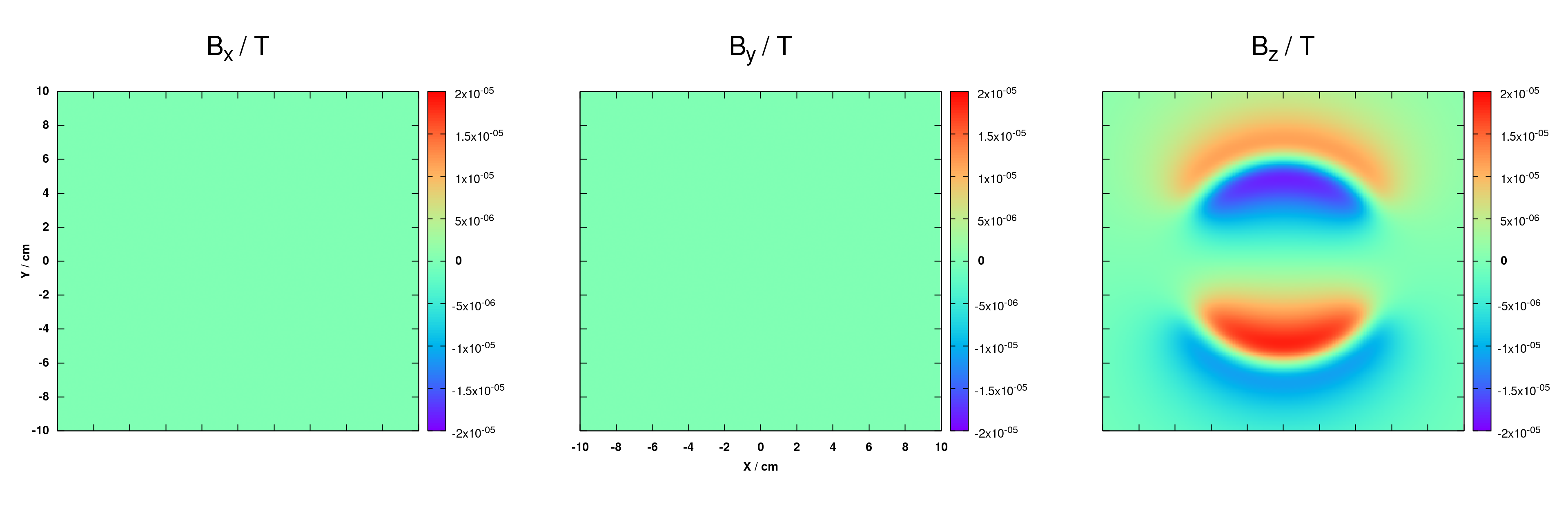
In later versions of the PyPPM, I'd also like to include X- and Y-shims:
![]()
![]()
The Z-shim is substantially easier to build, as it's just two counter-wound solenoids. In fact, it's a Maxwell coil, with the center solenoid removed, and one of the solenoids reversed.
The X- and Y-shims are a bit trickier. They are based on Golay coils, and will need a bit more thought on implementation.
Right now, I'm waiting on magnet wire from eBay. Stay tuned!
-
It finally works!
06/09/2014 at 01:24 • 2 commentsThe very first signal
After several years of failure with this project, I finally acquired a signal! The first hint at a signal came from averaging 128 scans (almost an hour of data collection!) down in the basement of the University of Nebraska chemistry building:
![]()
Blue shows the acquired signal without polarizing, and green is with polarizing.
The hump at 1775 Hz corresponds to a field strength of 41 microTesla, which was verified by my phones MEMS magnetometer. The peak is so broad because of massive field inhomogeneity caused by nearby iron structures that distort magnetic field lines. The sharper signals that appear in both spectra are (mostly) harmonics of the 60 Hz mains frequency.
While this was promising, it was nowhere near the expected performance of the PyPPM. So, I had to test it further...
Confirmation that the PyPPM works
A few weeks ago, I took the PyPPM out to a small field that was about 50 meters away from roads, electrical wires or buildings. After 32 scans, the resulting signal was (a) beautiful and (b) unequivocal proof that the PyPPM works! :)
![]()
The field here is roughly 54 microTesla, and even out in the field, I could still pick up sources of interference! The next step is definitely to design a humbucking sensor coil...
PyPPM: A Proton Precession Magnetometer for all!
A device for conducting Nuclear Magnetic Resonance experiments at Earth's field