jaromir.sukuba
-
This project is dead now
11/25/2015 at 11:08 • 0 commentsSorry for that, but it is officialy dead now. Last year I had no motivation to continue with it - the development consumed some money and a lot of time - in the meantime I sold spectrum analyser, high voltage sources to make the money back, at least partially.
I think the concept is still valid and feasible, but the amount of experimenting needed is unbearable for hobby project. All my output from this project is conserved here, for future reference, so anyone can catch up and continue.
-
First results, or something like that
08/26/2014 at 09:29 • 0 commentsWell, my project didn't get into first fifty -
https://hackaday.io/list/2864-The-Hackaday-Prize%3A-Semifinalists
Seems like I didn't emphasise words Arduino and RaspberryPI enough nor list all open-source components of the project. Nevermind, the show must go on.
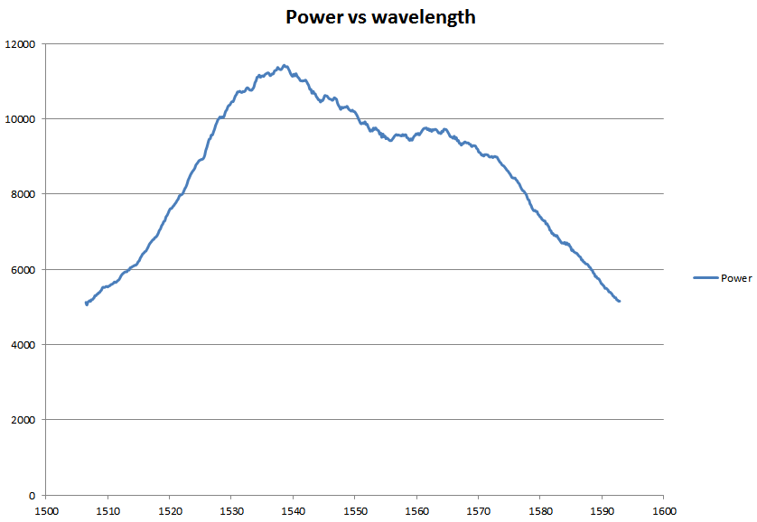
I asked my friend in local university laboratory to measure the spectral image of my assumed LPG. It doesn't look very much convincing, but the notch around 1555nm looks like I'm on the right track.
![]()
-
A few destroyed fibers
08/19/2014 at 10:05 • 0 commentsI tried to inscribe the LPG into fibers. At now I'm trying to achieve something, with no measurement. I found it is quite difficult to find proper combination of arc power, arc time and weight (strain) on fiber. However I got some partial results, looking actually quite good.
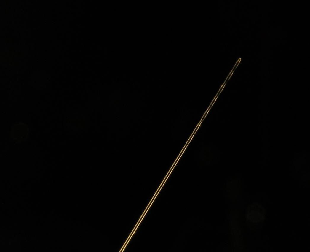
![]() The photo of this 125um thin fiber was being shot with my Canon PowerShot SX150 IS with no special optics. Nice job for this cheap camera. You can clearly see the places at the end of fiber, periodically thinner than the rest of the untouched fiber - this should be the parts, where fiber and cladding modes meet and do a phase cancellation, as explained before.
The photo of this 125um thin fiber was being shot with my Canon PowerShot SX150 IS with no special optics. Nice job for this cheap camera. You can clearly see the places at the end of fiber, periodically thinner than the rest of the untouched fiber - this should be the parts, where fiber and cladding modes meet and do a phase cancellation, as explained before.
However, this fiber broke during the inscribing, as well as few others. I have to fiddle with power a little more. -
LPG fiber optic sensors, a bit of theory
08/16/2014 at 16:17 • 0 commentsI started something about LPG fibers here
http://hackaday.io/project/1379/log/3243-how-do-fiber-optic-sensors-work but I still get questions about the topic, so I decided to insert another log about the principles behind the LPG fiber optic sensors (LPG FOS).
Single mode optical fiber consists of four main parts:
![]() 1: Optical core (outer diameter 9um), carrying the useful information.
1: Optical core (outer diameter 9um), carrying the useful information.2: Cladding (outer diameter 125um). It has different refraction index compared to core, helps to keep the light inside the core.
3: Buffer: first line of mechanical protection (outer diameter cca 0,25mm), it has nothing to do with light.
4: Jacket: outer mechanical protection with various thickness (outer diameter 0,6 to few mm).
In normal conditions, there are no active cladding light modes (= no light propagates throught cladding), only one core mode (= light propagates through core, however different refraction index of cladding keeps the core mode inside the core) and optical fiber is transparent as expected, assuming normal telecommunication range of 1500-1600nm (near infrared light). However, under special conditions, like microbend or damaged fiber (in my case - slight "destruction" of fiber structure with high temperature of electric arc), part of the light escapes into cladding. Nothing special happens, unless the perturbation is periodic - at the perturbation points the core and cladding modes are mixed (part of cladding mode gets into core and vice versa). Because speed of light in cladding is slightly different compared to core (due to different refration index), the mixed modes are out of phase, phase cancellation for some wavelengths is observed.
![]() This effect increases insertion loss (=the fiber is less "opaque" for some wavelengths) at specific wavelengths. Spectral characteristics of the fiber looks like this
This effect increases insertion loss (=the fiber is less "opaque" for some wavelengths) at specific wavelengths. Spectral characteristics of the fiber looks like this![]() If we concentrate on particual section of the spectrum, like 1480-1550nm, there is only one peak. Because the phase cancellation conditions depend on physical dimensions between perturbations (grating period), change of the grating period changes also the peak wavelength. Grating period can be changed by stressing the fiber (normal glass fiber can be elongated up to few percents with its elastic, reversible deformation), so applying mechanical strain on the fiber with LPG also changes peak wavelength accordingly (to higher wavelentgths). After releasing the strain, mechanical properties of fiber retrun to normal and peak wavelength. Reversing the observation: from the change of wavelength we can determine strain applied to sensor and this is what looks like tensometer - it actually IS tensometer! ;-)
If we concentrate on particual section of the spectrum, like 1480-1550nm, there is only one peak. Because the phase cancellation conditions depend on physical dimensions between perturbations (grating period), change of the grating period changes also the peak wavelength. Grating period can be changed by stressing the fiber (normal glass fiber can be elongated up to few percents with its elastic, reversible deformation), so applying mechanical strain on the fiber with LPG also changes peak wavelength accordingly (to higher wavelentgths). After releasing the strain, mechanical properties of fiber retrun to normal and peak wavelength. Reversing the observation: from the change of wavelength we can determine strain applied to sensor and this is what looks like tensometer - it actually IS tensometer! ;-)Now you can ask, what is the point of all the effort put into this kind of sensor? Electrical tensometers exists and work for decades and there is little reason for use anything else, you may think. Partially, you are right, however measuring signals from tensometers is getting tough (due to its low signal levels) if you wish to connect it through long cable or in electrically noisy environment. The main advantafe of fiber optic sensors is that there is actually no electric signal at the measured region (the spectromter has to be electric, of course), so it is inherently imunne to electromagnetic interference or even ionizing radiation. What more, no electricity at the place means absolute safety for critical environments, like combustive gasses or for biological experiments. There is no problem running few kilometers (!) of fiber to sensor with no negative influence on measurement precision or speed.
One can inscribe more than one LPG (with different peak wavelengths) into various places of signle fiber, creating multi-point sensing system withing single thin (250um) optical fiber.
All those features makes fiber optic sensors the sensors of future. It is already used in high-end civil engineering projects and massively in aerospace and military field, however for normal mainstream use it is too exotic and expensive; hopefully this will change a bit with this project.
-
3D printed parts and sparks
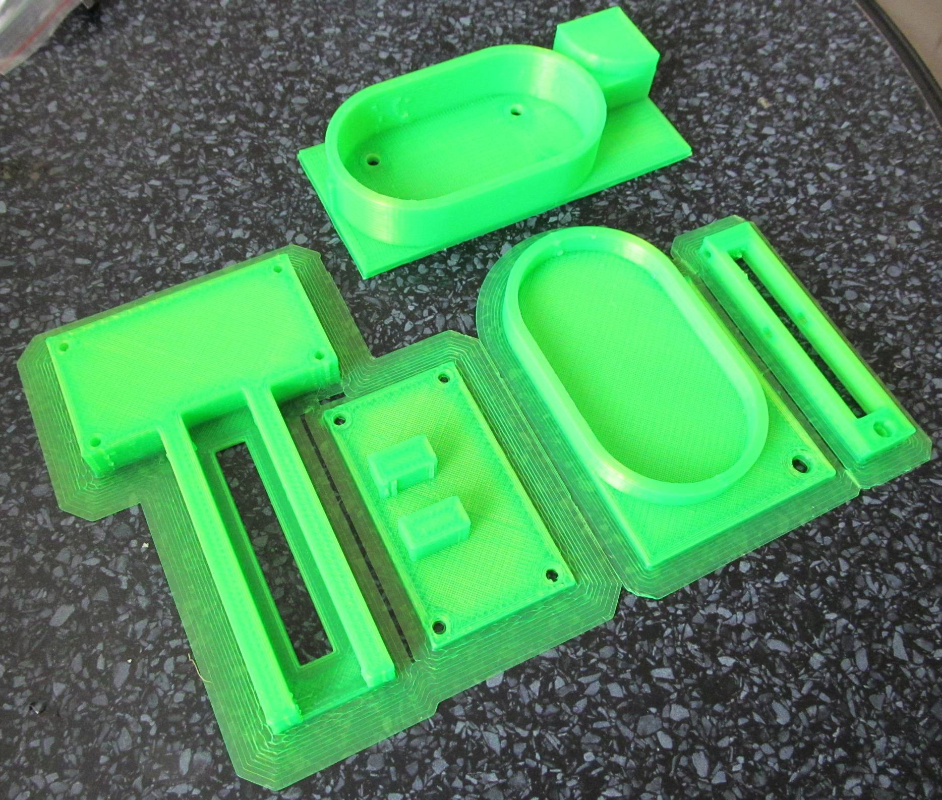
08/14/2014 at 10:15 • 0 commentsI designed parts of LPG inscriber in FreeCAD and printed on my MendelMax.
![]()
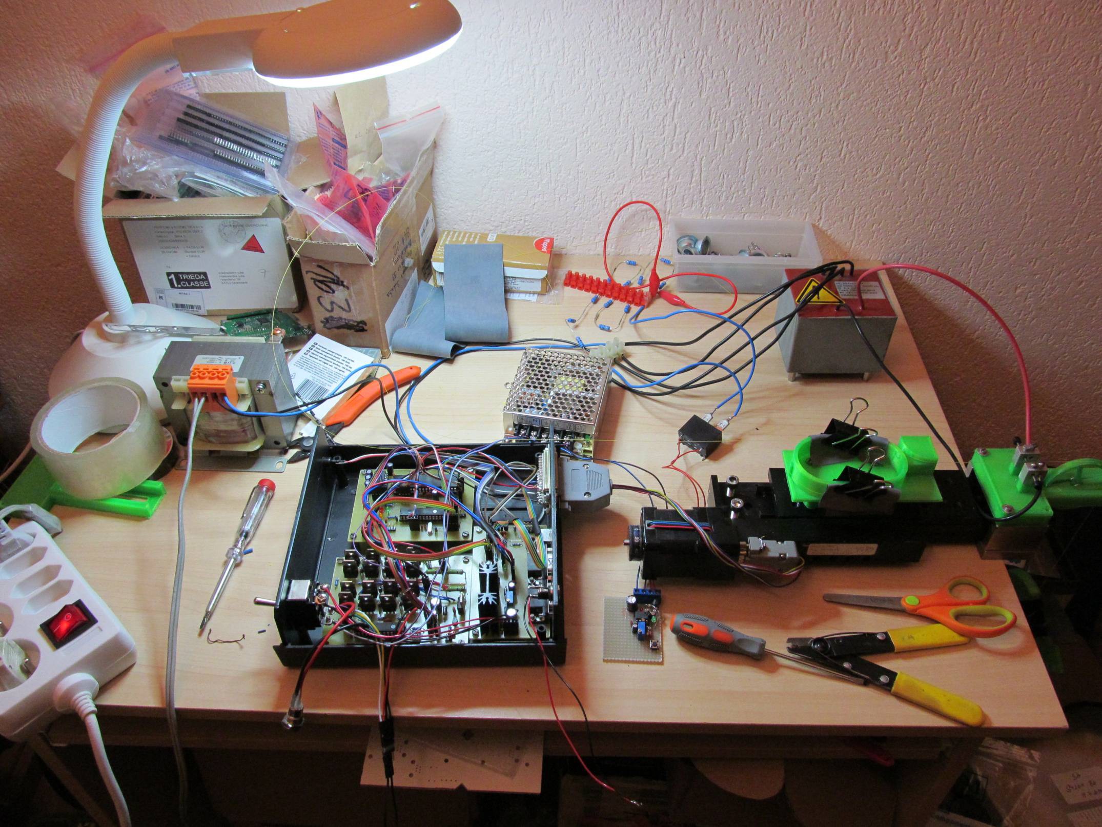
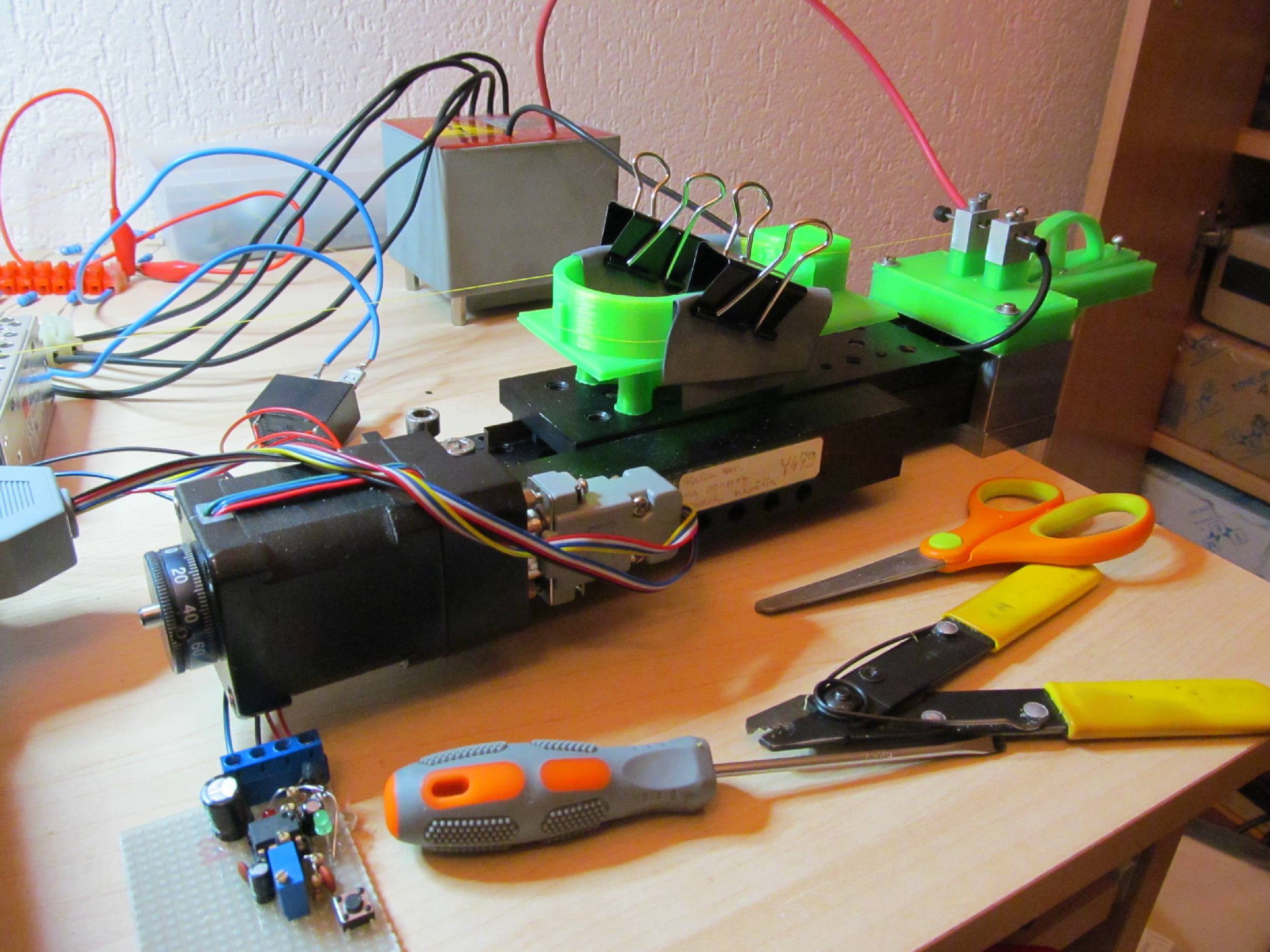
Then I attached it to my translation stage (no rework was needed, it was OK on first try) and connected stepper motor driver. Firmware in driver is brain-dead simple - afer reset it just does number of steps, hardcoded in source. To adjust number of steps, I need to recompile and burn new firmware. It is enough for development.![]()
I played a bit with electric arc. At first I had transformer directly connected to electrodes, but the arc was quite wide. So I tried single way rectifier on secondary and resistor current limit on primary side. I didn't have HV rectifier in my junk box (5kV effective secondary voltage, more than 7kV peak-to-peak) si it was executed as 12 pieces of jelly-bean 1N4007 diodes. Theoretically, 8 would be enough, but I ut some safety margin here. Resistor limiter is just 12 resitors 68Ohm/2W in series, because I had it on hand.
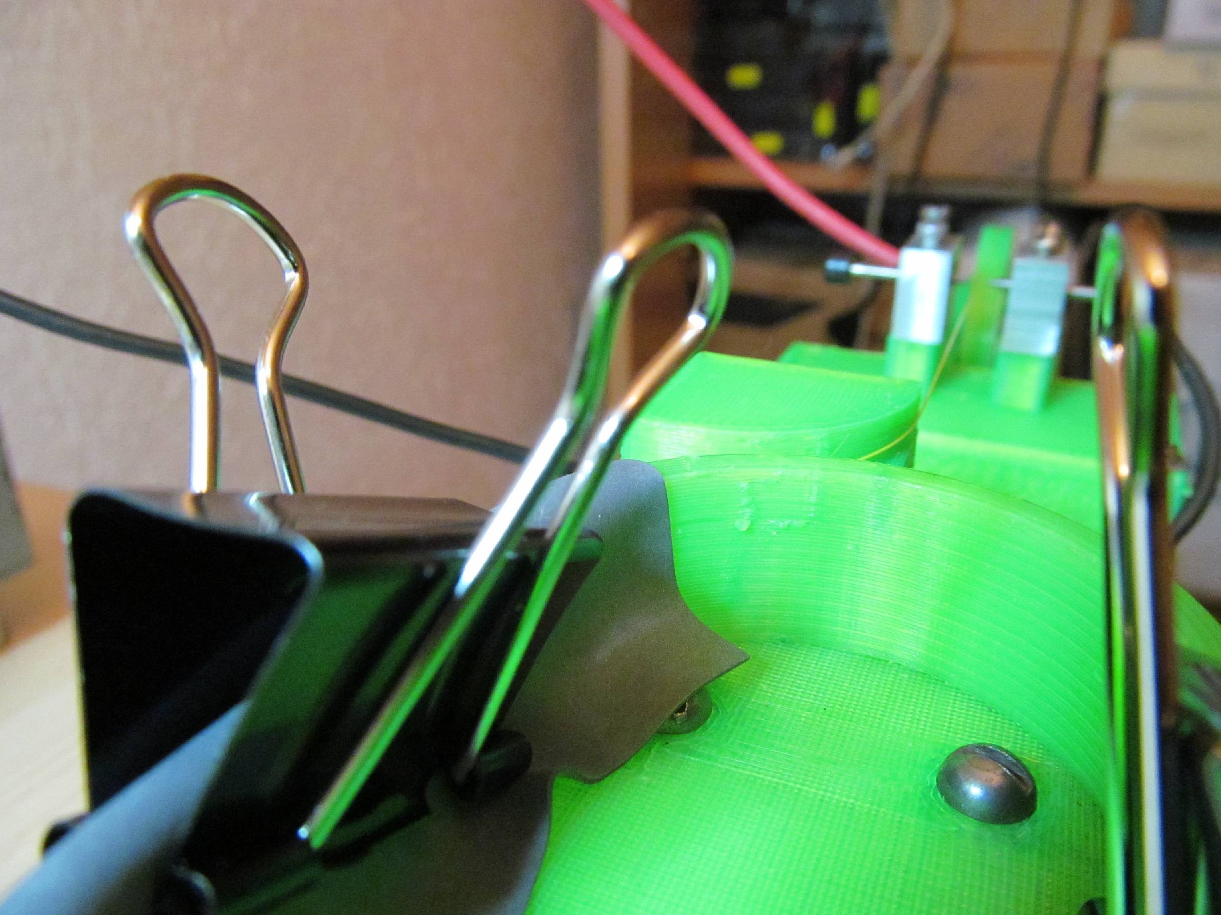
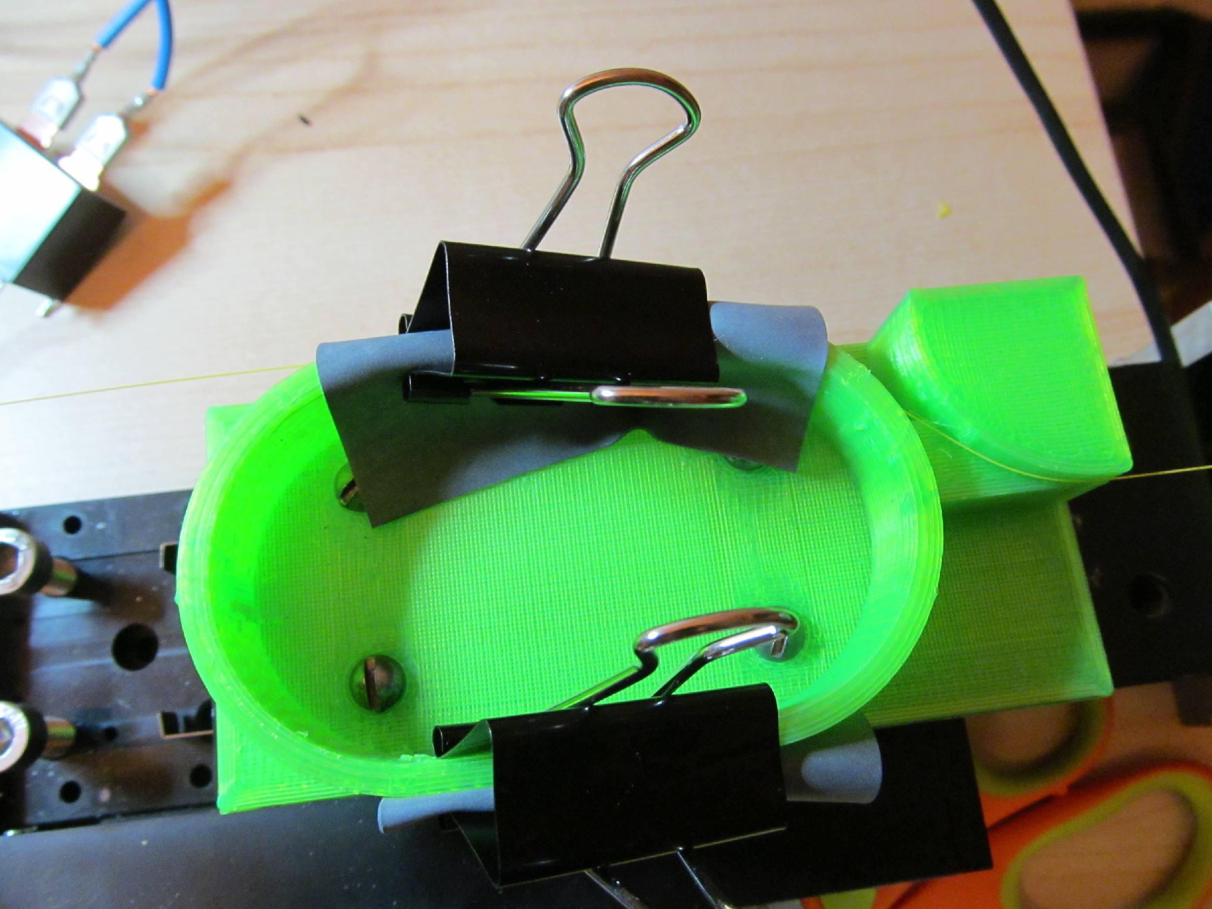
Rectifier didn't help a lot, but current limiting resitors did. Arc is now thinner and easier to control. By bridging the particular resitors I can control the amount of current flowing through secondary (and arc too), so I can increase the arc power later, if needed.Then I took optical fiber and secured it in holders using office clips and piece of rubber (rubber bandage from medical shop). The total weight on the free end of fiber was approximately 150g.
At first I tried applying arcs on the fiber, with no optical measurement. At full power (limiting resitors bypassed) I cut the fiber, at low power (all limiting resitors in place) I got no visible (using microscope) change on the fiber. So it seems that I have good control over the arc power and I can start working on the spectrum analyser to observe changes of spectral response during LPG inscribing.Some more photo:
![]()
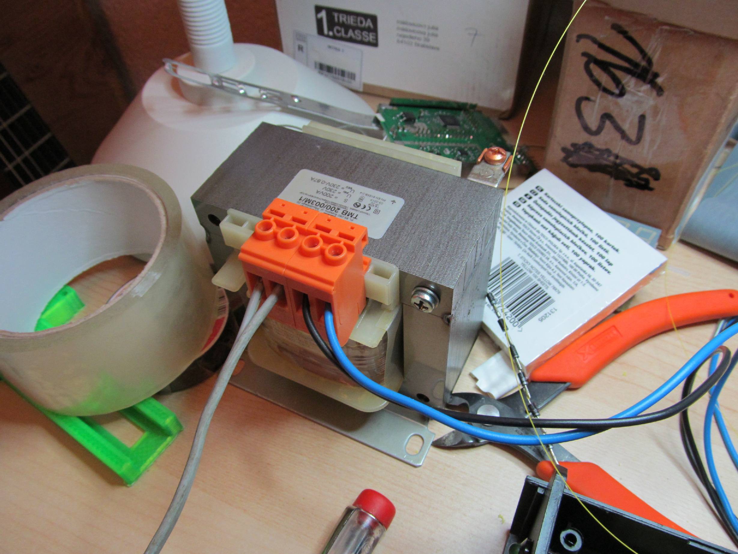
I'm using isolation transformer to keep most of the circuit isolated from mains. At least a bit of safety.
![]()
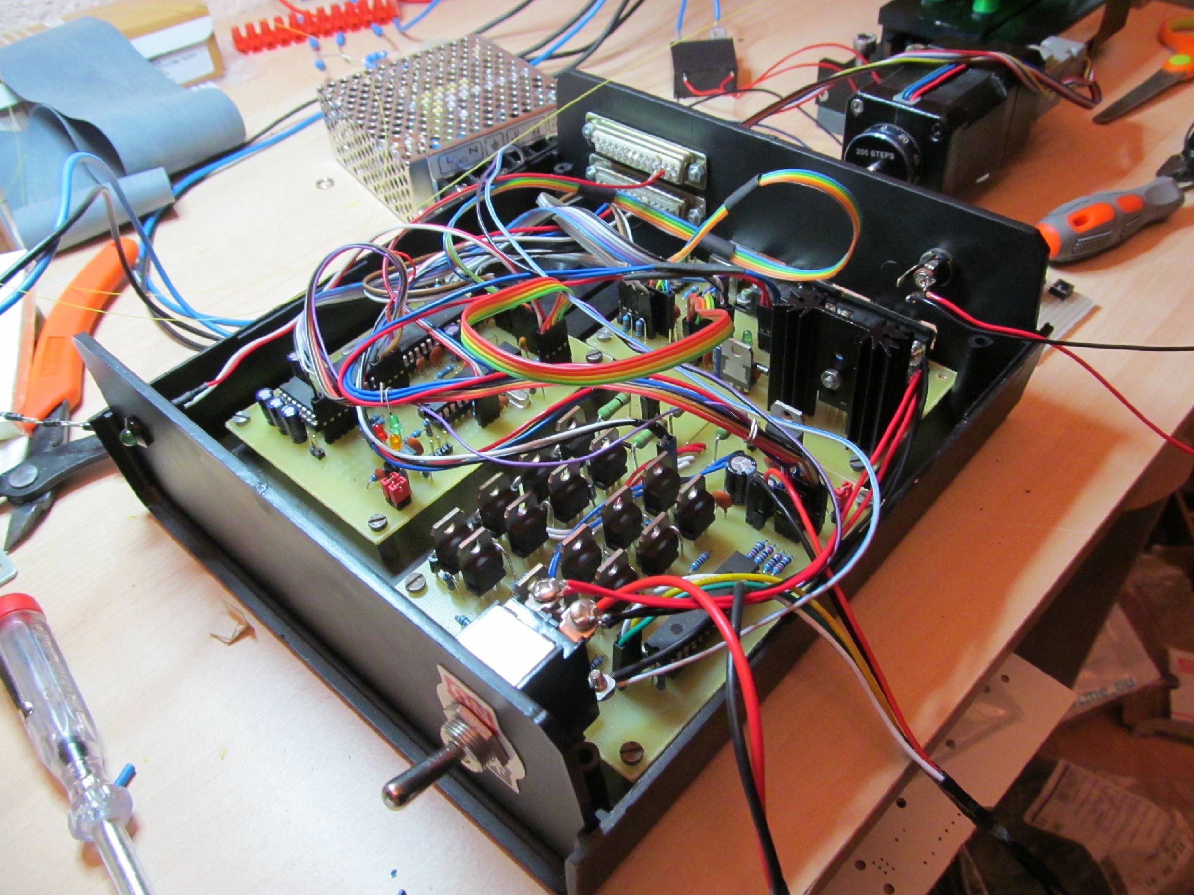
Stepper motor controller. A bit of cable mess, but it works.
![]()
Translation stage with 3D printed parts installed.
This translation stage is professional with 1um resolution and quite high pulling force, completely out of price tag I set before. It will be swapped for something less expensive (maybe DVD-ROM translation stage or something like that) after I'll confirm it's working.
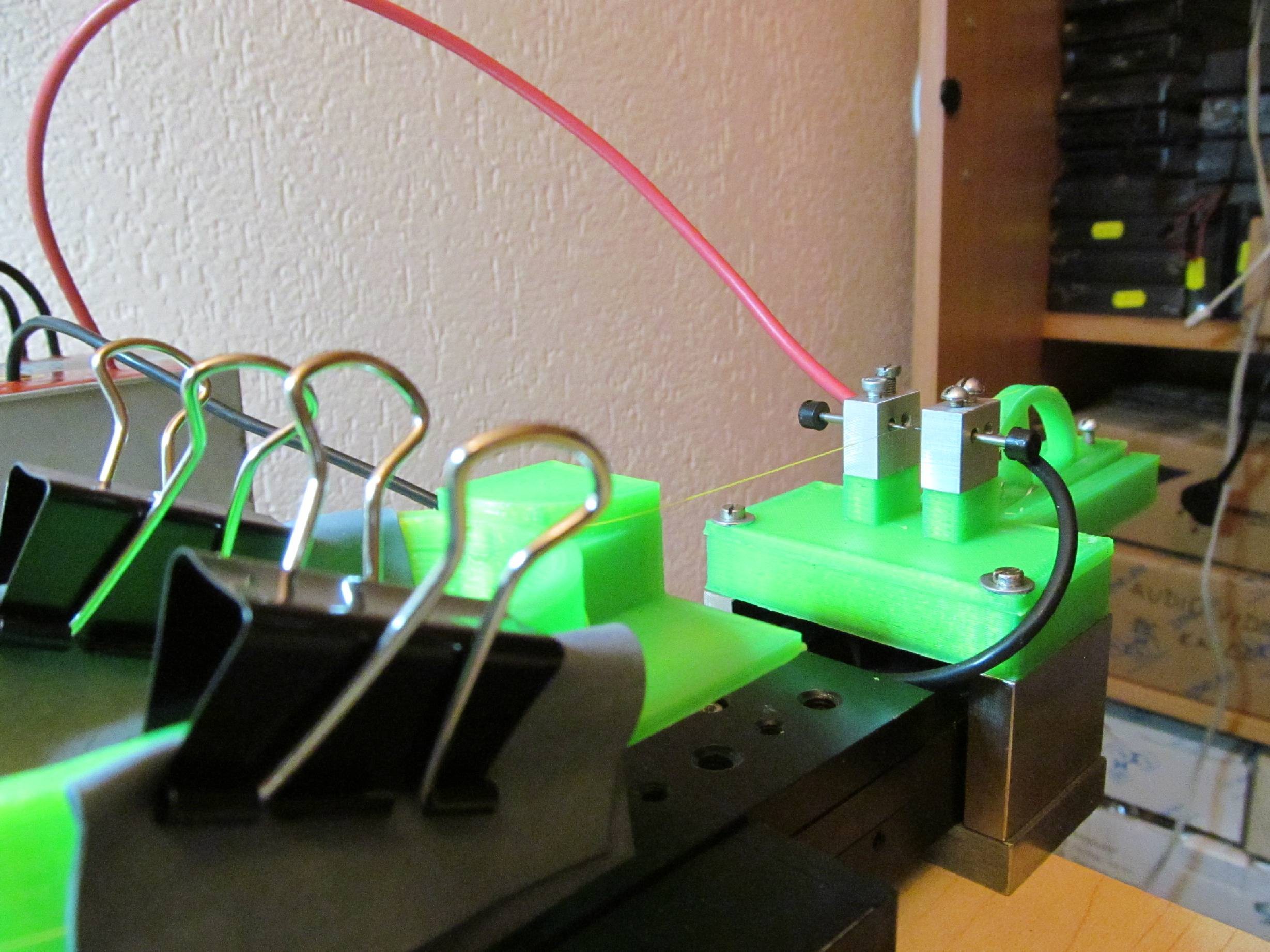
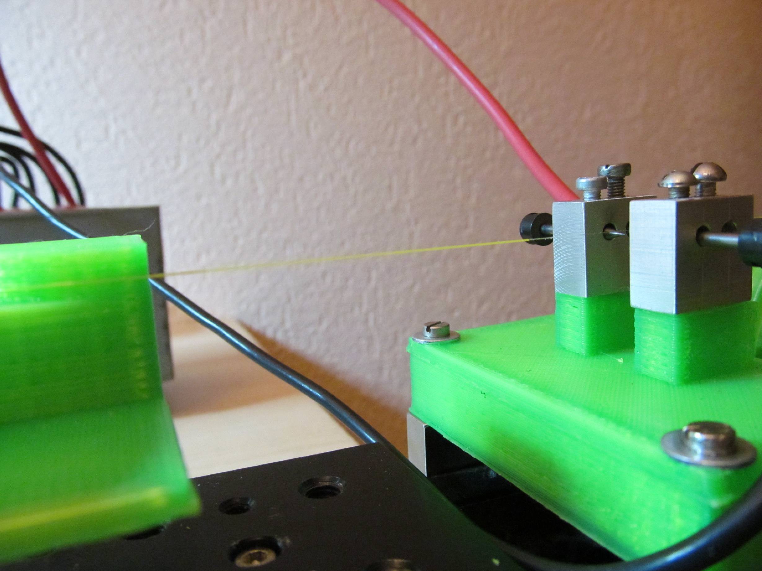
Some more photos of how is fiber attached to the moving part of translation stage.
![]()
![]()
![]()
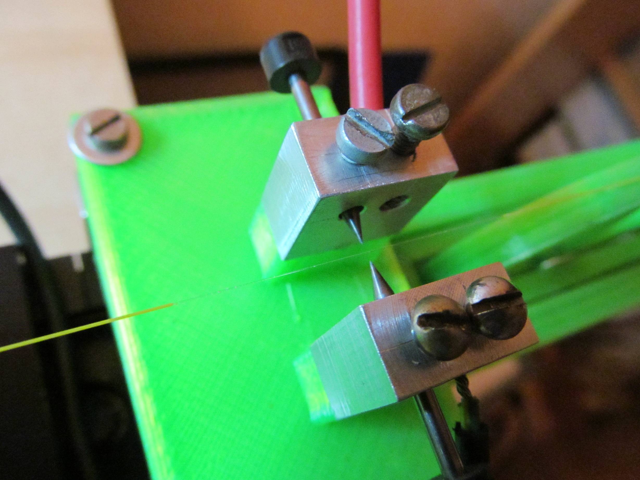
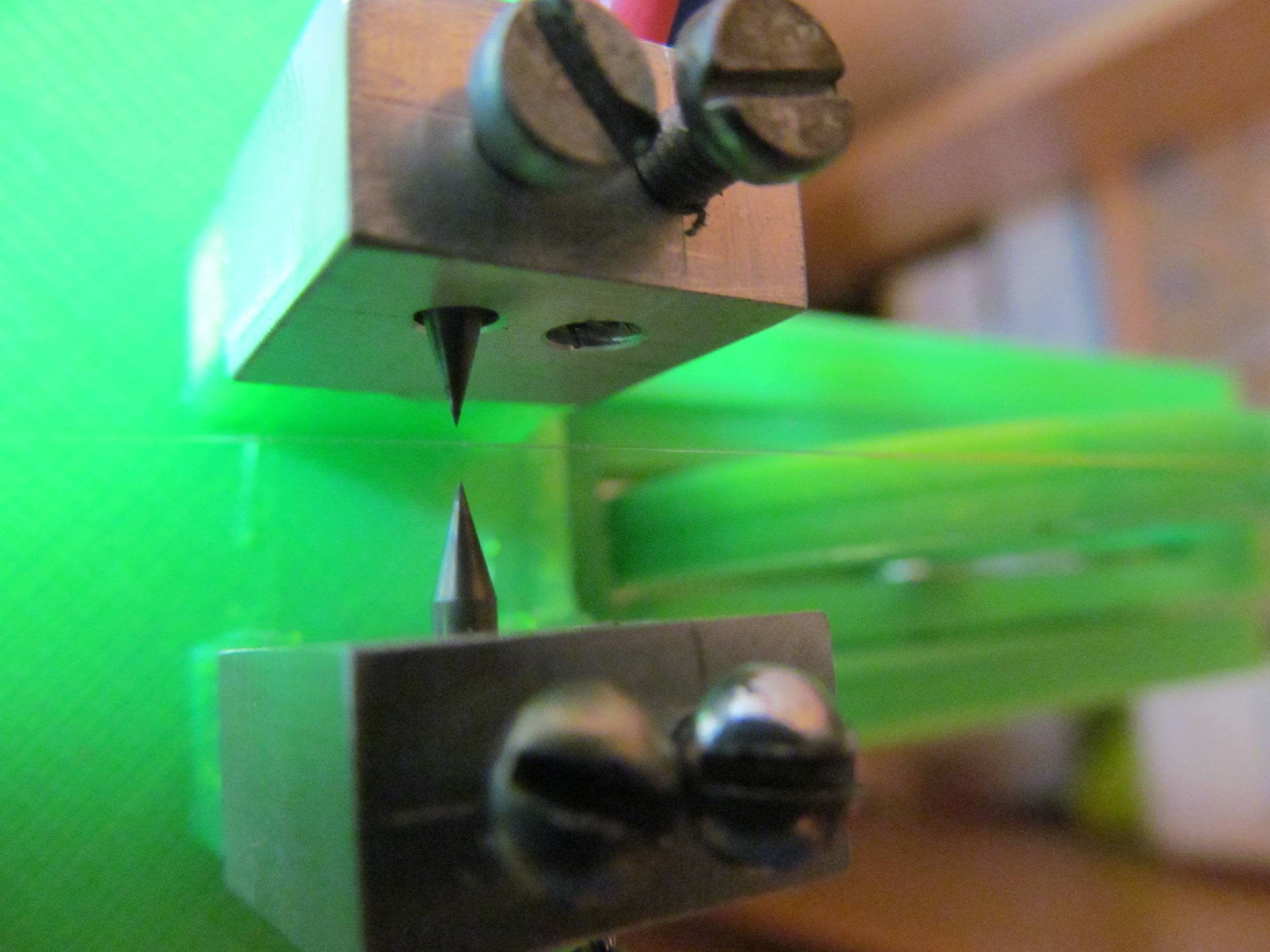
And here is fiber between electrodes.
![]()
![]()
![]()
-
Components for for LPG inscriber and spectrometer
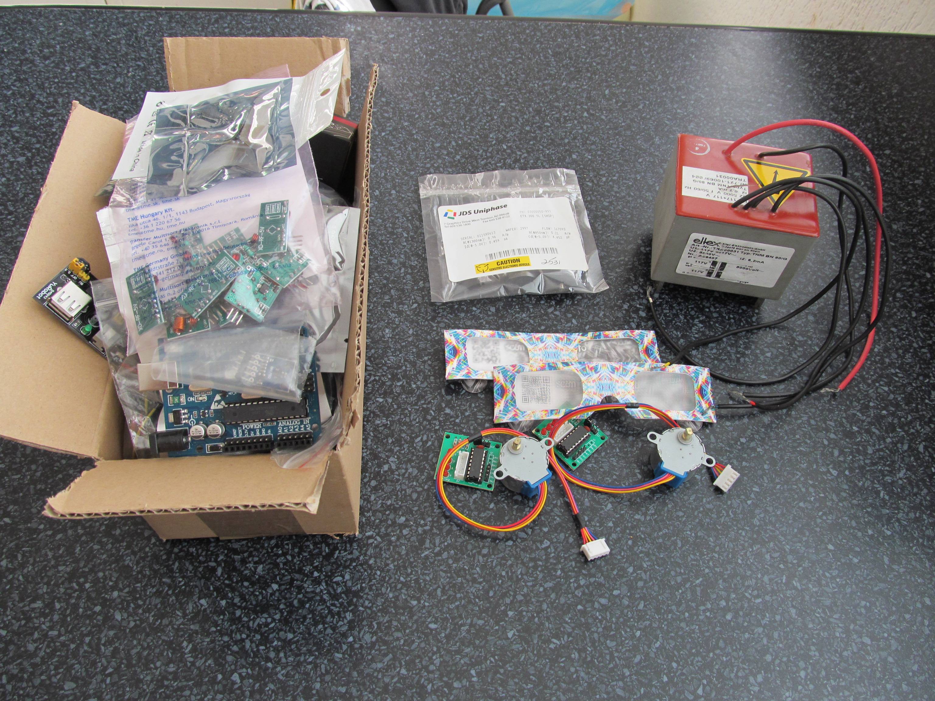
07/03/2014 at 07:28 • 0 commentsAfter a few weeks of waiting, I managed to get all the components I need for start.
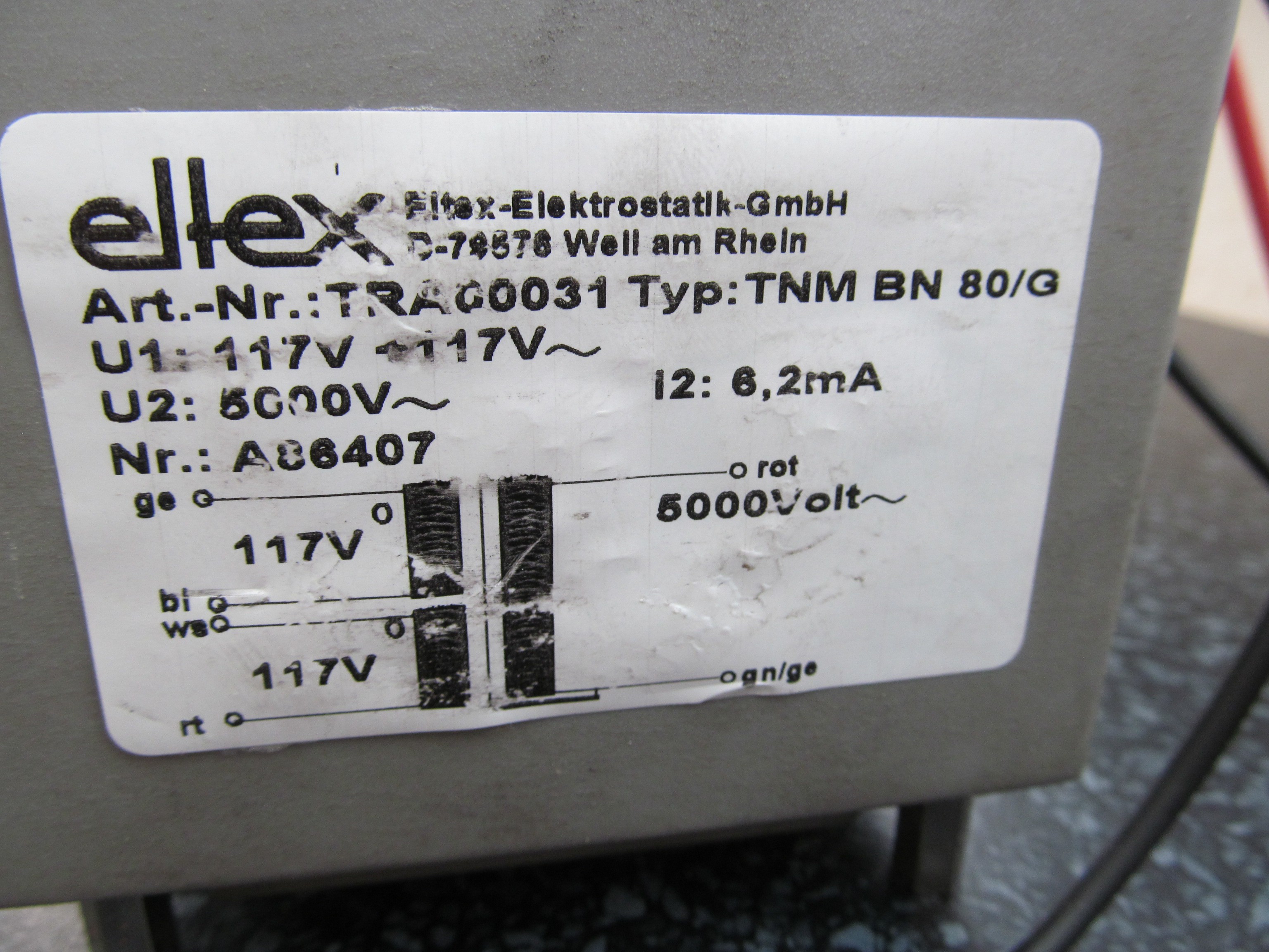
For example, this nice transformer. Yep, it's 5kV.
![]()
I'm going to inscribe the long period grating (LPG) into fiber using electric arc and this guy (and I have it's identical brother too) should help me with it.
![]()
Except of that, box of cheap chinese boards that are sometimes quite handy for quick experiments, some stepper motors with huge gear ratio (for scanning spectrometer), party galasses with polarization foil for spectromter difractor and plastic bag with IR photodiode.
![]()
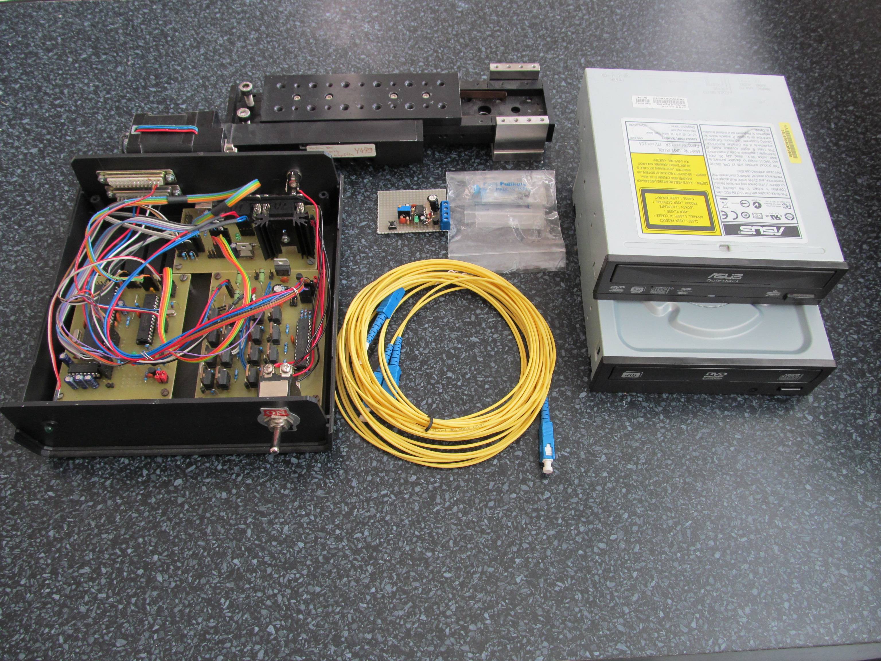
I took out one of my projects I did many years ago, when PIC18F2550 was absolutely new hot chip. That PCB's in that ugly plastic enclosure are stepper motor controller with some regulating circuitry. Nowadays, I would do it completely differently, but nothing can stop me from repurposing this for initial experiments. I expect final version to be built on modern components.
Fortunately, I got my hands on precise and quite expensive translation stage (above the ugly plastic enclosure) and this will be good start for experiments with LPG inscribing (I'm going to need precise fiber movements for that). This translation stage will be definitely replaced by something low-cost, as it's price is one order of magnitude higher than whole budget.
Some optic fiber patchcords, PCB with monostable multivibrator to control arc timings, plastic bag with wolfram electrodes (replacement parts for proper fusion splicer) and finally - DVD ROM. No DIY optical project would be complete without parts from those.
Now I'm going to print some plastic parts on my MendelMax and proceed to practical experiments.
-
How do fiber optic sensors work
06/06/2014 at 11:14 • 0 commentsThere are a lot of possible methods to achieve the goal, but I'll focus on sensors being wavelength specific optical devices.
In theory, simplest one is fiber Bragg grating, FBG.
FBG
Quote from wikipedia:
A fiber Bragg grating (FBG) is a type of distributed Bragg reflector constructed in a short segment of optical fiber that reflects particular wavelengths of light and transmits all others. This is achieved by creating a periodic variation in the refractive index of the fiber core, which generates a wavelength specific dielectric mirror. A fiber Bragg grating can therefore be used as an inline optical filter to block certain wavelengths, or as a wavelength-specific reflector.
![]()
Pretty simple, huh?
In fact, the only thing one needs to create FBG is periodic change in refractive index of core (just to be sure – check out how the optic fiber works). This can be done using laser, for example. Imagine shooting single laser ray on fiber, partially “destroying” the core, then move the fiber by some distance, shooting again, rinse and repeat until a lot of nicks are made. Notice the uncertain words “partially”, “some”, “a lot of”. The distance between the nicks is actually easy to determine – Wikipedia again
The refractive index will typically alternate over a defined length. The reflected wavelength (), called the Bragg wavelength, is defined by the relationship,
where is the effective refractive index of the grating in the fiber core and is the grating period.
The other parameter is usually subject of experiments, especially when it comes to laser power. The needed amount of shots is usually in hundreds or thousands.
While making FBG seems simple, there is a minor problem with positioning system for FBG inscribing. To achieve wavelength of ~1,5 micrometer (suitable wavelength for fiber optic systems), the needed fiber movement is in order of hundreds of nanometers. It could be nice challenge, but there are simpler ways to achieve the goal – long period gratings (LPG).
Long period grating
LPG is done by periodical coupling light of core and cladding (I assume you have still opened the tab with this Wikipedia article). Fortunately, the periodicity has to be much longer compared to FBGs, just in order of fraction of millimeter; the coupling can be done by partially “melting” core and cladding together, using laser, hot wire or electric discharge. What more, the amount of those couplings is a few dozens.
Now we are getting somewhere. In theory, one should just take standard single-mode optical fiber, strip the coating off and apply laser/discharge/high temperature into tiny region of fiber, move on, apply again, move … etc. until a LPG is done.
How does the sensor work, after all?
Now we have single grating on fiber, what to do with it? Well, when you look at the fiber sensor spectrum with spectrometer, you can see peak, characteristic for given sensor geometry. When the geometry is changed, the spectrum also changes. Imagine you have peak wavelength at 1550nm when fiber is resting. Now you can take the fiber and pull it (glass core fibers can be pulled up to few percent), the peak wavelength will move to 1551nm, for example. When you release the fiber, it will move back to 1550nm.
Voila, we have tensometer.
What’s next?
Now I need to find out two things:
1, How to measure spectrum of the fiber, creating optical sensor interrogator
2, How to make the core/cladding joints.
I have some thoughts of how to do it, so stay tuned for updates.
DIY fiber optic sensors
Make your intrisic fiber-optic sensor system at home, using your mbed/arduino, RaspberryPI and cheap optical fibers
 The photo of this 125um thin fiber was being shot with my Canon PowerShot SX150 IS with no special optics. Nice job for this cheap camera. You can clearly see the places at the end of fiber, periodically thinner than the rest of the untouched fiber - this should be the parts, where fiber and cladding modes meet and do a phase cancellation, as explained before.
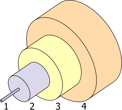 1: Optical core (outer diameter 9um), carrying the useful information.
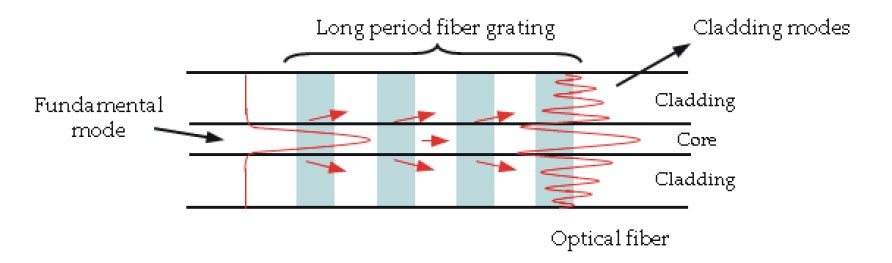 This effect increases insertion loss (=the fiber is less "opaque" for some wavelengths) at specific wavelengths. Spectral characteristics of the fiber looks like this
 If we concentrate on particual section of the spectrum, like 1480-1550nm, there is only one peak. Because the phase cancellation conditions depend on physical dimensions between perturbations (grating period), change of the grating period changes also the peak wavelength. Grating period can be changed by stressing the fiber (normal glass fiber can be elongated up to few percents with its elastic, reversible deformation), so applying mechanical strain on the fiber with LPG also changes peak wavelength accordingly (to higher wavelentgths). After releasing the strain, mechanical properties of fiber retrun to normal and peak wavelength. Reversing the observation: from the change of wavelength we can determine strain applied to sensor and this is what looks like tensometer - it actually IS tensometer! ;-)