helge
helge-
starting small
07/15/2018 at 23:45 • 0 commentsBad puns about "starting on a small scale" aside, using compact low profile kitchen scales should have its advantages from development to practical use, particularly because 3-5L water jugs are both cheap and keep a small footprint perfectly matched to kitchen scales and it might be interesting to directly monitor plant pot weight.
Motivated by easy availability, the local supermarket was searched and two kitchen scales with different geometries were acquired.
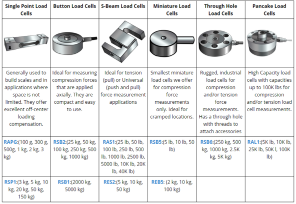
Load cell types
While industrial applications call for button and pancake load cells, kitchen scales seem to work just fine with single point load cells of the cheap kind. Here's a bit of load cell taxonomy:
![]()
http://www.loadstarsensors.com/what-is-a-load-cell.html
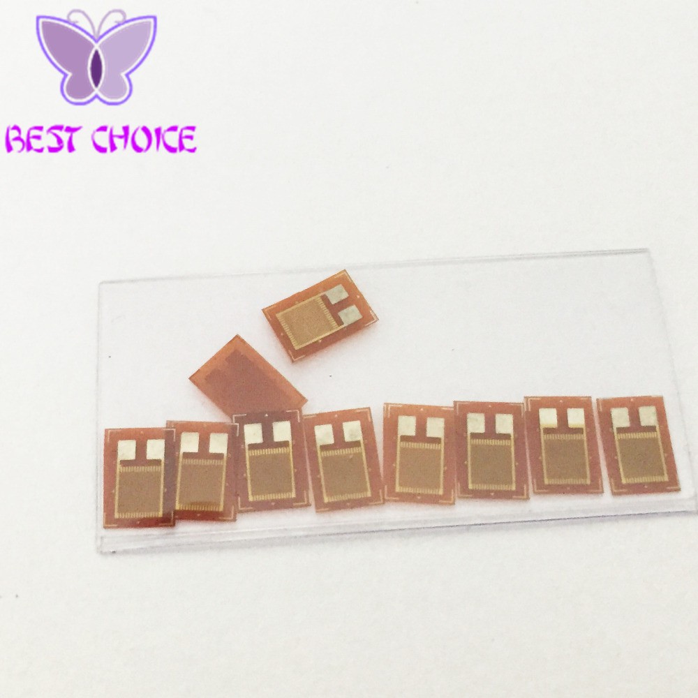
With strain sensitive resistors as the fundamental building block:
![]()
(AliExpress)
Pairs are used to detect simultaneously occuring tensile and compressive strain on adjacent sides of a bending beam.
![]()
(AliExpress)
![]()
http://www.loadstarsensors.com/what-is-a-load-cell.html
There may be some cancellation of drift related to cyclic stress but both hysteresis and offset problems seem to arise from the load cell body as opposed to the sensing element. (https://de.wikipedia.org/wiki/Dehnungsmessstreifen#Hysterese)
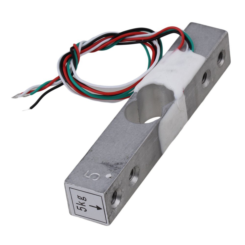
Specimen #1 ...
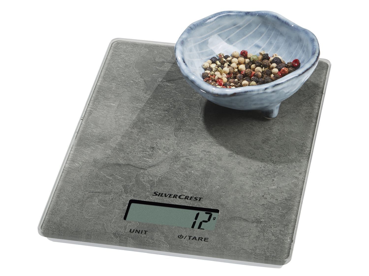
has a single mounting point and looks pretty much like this scale:
![]()
Inside there's likely just a single point load cell as shown above. Some scales use the same hollowed-out aluminium beam but replace the resistive lements with a plate capacitor. These obviously cannot be used for our purposes without appropriate capacitance-to-digital conversion.
The resistive strain gauge type implied here has s differential output and should work with industrial force transmitters (e.g. https://www.bosche.eu/en/scale-components/weighing-indicators/indicators/weight-transmitter-wts ) as well as embedded solutions (discussed below).
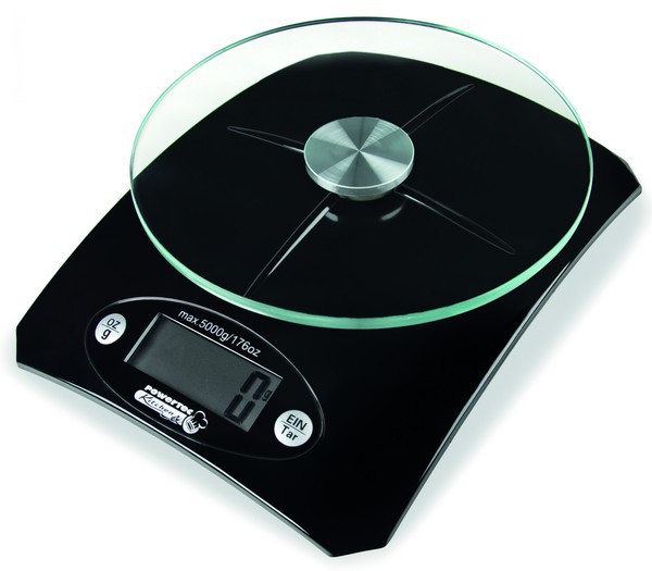
Speciment #2 ...
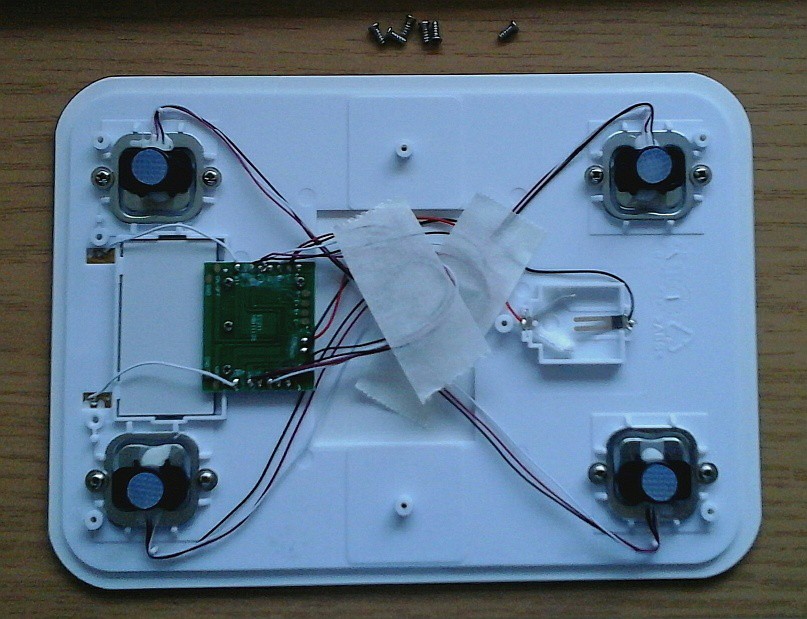
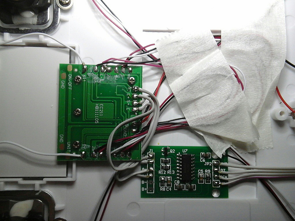
The local supermarket sells these rather flat and simple Silvercrest SKWD A1 scales with a 5kg range and capacitive touch buttons.![]()
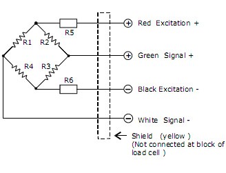
From the back side a set of 3-wire strain gauges can be seen. Just like in the body weight scale torn down before they are connected to form a Wheatstone bridge that outputs a sum signal differentially.
![]()
Conveniently the test pads breaking out the excitation (E+, E-) and sense nodes of the bridge (S+, S-) are denoted in the silk screen:
![]()
Good enough, we'll run with that.
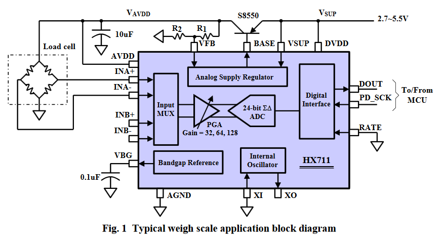
HX711 load cell frontend with 24 bit ADC
$1 buys a PCB with an HX711 IC, discrete linear regulator and some passives these days. Starting with a quick peek into the datasheet:
https://www.mouser.com/ds/2/813/hx711_english-1022875.pdf
All strain gauge elements being resistive, the differential output amplitude scales with the excitation voltage V_AVDD. The common-mode voltage does so too, but it's suppressed and only relevant in as much as the ADC is built to operate around V_AVDD/2 and must not go below AGND + 1.2 V (see KEY ELECTRICAL CHARACTERISTICS). Furthermore VFB is adjusted to VBG = 1.25 V so one can deduce the excitation voltage configuration from resistor codes before buying the PCB online.
![]()
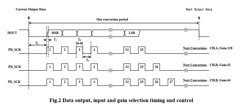
The serial interface is pretty minimalistic - there are no configuration commands, no !CS and no MOSI pin.
![]()
DOUT is used as synchronous MISO and asynchronous "data ready" signal while configuration is implemented by counting clock pulses. This might spell trouble in some situations due lack of a proper chip select. "PD_SCK clock pulses should not be less than 25 or more than 27 within one conversion period, to avoid causing serial communication error."
When considering co-existence alongside I2C lines, it's interesting to see that "when PD_SCK pin changes from low to high and stays at high for longer than 60 µs, HX711 enters power down mode."
Recovery: "When PD_SCK returns to low, chip will reset and enter normal operation mode."
So it seems HX711 is ok with being fed some garbage after proper operation when SCK is kept high for a while, then reset and be back in operation.
Hacker-friendly white goods
With a clear pinout and room to stick down another PCB with double-sided adhesive tape, the modification is straight forward (tm).
![]()
Channel A offers 128x gain and is the default channel selected after reset, corresponding to +/-20mV full-scale differential input voltages (also matching industrial load cells like the TE FC2311-0000-1000-L). The resulting FS range of the load cells in the scale is unknown right now but it's a matter of soldering the connections to the B inputs and a change the number of clock pulses to adapt to different sensor elements.
The kitchen scale now has a new cable sticking out on the bottom side. Pinout:
![]()
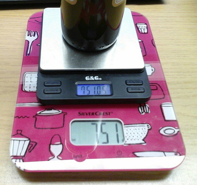
Test after modification
Before replacing the back cover the excitation voltage was measured in operation and found to be around 2.4V. If the HX711 exictation voltage is made to coincide with the scale exc. voltage, the scale electronics might be used alongside the digital readout although the tare step on startup will interfere with the intended display function. One will have to lift the measured object off the scale before or after zeroing.
![]()
After the mod and with the 3V coin cell back in place the original board doesn't seem to mind the added HX711 headcrab. This is not at all obvious because the behaviour of the unpowered HX711 is not specified.
Another test is conducted by injecting 2.4V without the battery to see if leakage currents can destroy the original scale circuitry (result: negative). If HX711 is immune to receiving 1.2V through the IN+, IN- pins when unpowered (edit: and 2.4V through E+ which will backfeed the regulator and possibly internal circuitry) the scale can continue being a regular scale without either part getting damaged.
Good to go? -
reservoir musings
05/03/2018 at 11:41 • 0 commentsIt's been put off long enough - let's see what can be done in terms of reservoir containers. The whole reservoir, while being an unpleasant necessity, is supposed to be inconspicuous and no-fuss to handle - funnel equals failure. "Just add water".
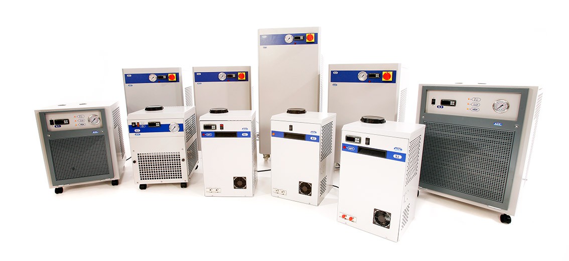
Units sold as "scientific water bath" or small-scale laboratory recirculating chillers have a lid on top that you can just lift off or open to refill and I like that idea. Somewhere between the lid and the 3/4" port there are the wide mouth lids:
![]()
The chiller in the lab has one of those and although you can refill with a bucket it's always a challenge not to spill anything.
Once you're willing to add a permanent shroud (e.g. a matching 3D printed part), new options are on the table. Maybe a canister with larger ID hose nipples would do the trick? One for venting and extrating tubes access while the other would be connected to the funnel?
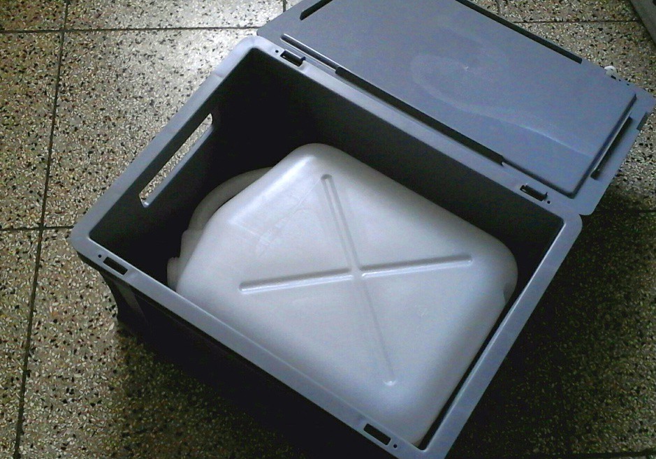
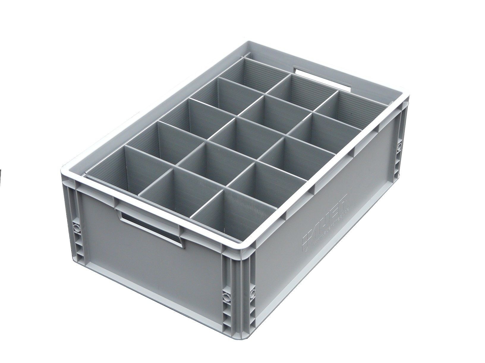
As fas as sloshing and splashing is concerned I like the idea of having a reservoir canister... so I got a 10L canister, only to change my mind. Ironically, it fits the 30x40cm² euro box very snugly:
![]()
And once we're there it becomes rather obvious what this story will digress into:
Maybe the simplest and most useful option is to just use a plain euro box- It's also hard to beat the sheer volume of that thing, plus it keeps out the light and thus suppress algae growth.
Add a laser cut divider to control sloshing. Maybe even a ready-made one will suffice?
![]()
A bonus of the laser-cut divider would be the ability to make the pockets unevenly shaped so they don't share a common fundamental sloshing resonance or add holes to create turbulent damping. Maybe that's me taking it a bit too far.
Handling:
- pull out the box from underneath the shelf
- lift off the lid, pour in more water, replace lid
- shove it back under the shelf
That should do it?
But then there is the grip opening which just screams "extendable funnel tray" at me, with the "open the darn lid" method as a fallback.
-
prototype readout hardware
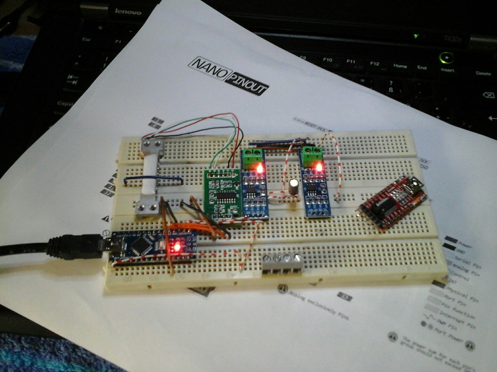
04/15/2018 at 18:16 • 0 commentsSince this is one of the projects that caters to beginners and experienced makers how don't have much time to spend on "just getting it to work", we're using microcontroller and breakout boards which are popular and readily available.
![]()
Here we have a 4-wire dummy load cell, HX711 breakout board, Arduino Nano V3 clone and two MAX485 breakouts for RS485. It's also planned to add an SK6812 LED ring for status indication and low water warning (annoyingly blinking red LEDs, you get the idea) but these have yet to arrive. Checking the voltages reveals that at least the load cell excitation and output voltages seem to be nominal.
Since it's a popular, open protocol and other industrial process automation equipment is also available, I'm thinking Modbus RTU might be the way to go. It's timing critical for the slaves so prototyping should be ok with an FT232 or UART-Ethernet interface.
To be continued.
-
cheap used personal weight scales
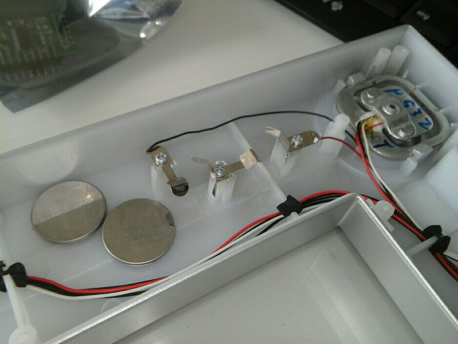
04/15/2018 at 18:08 • 0 commentsThey are everywhere, they're cheap and seem to work reasonably well. I can only assume that there are little to no surprises in terms of load cell selection. On a nice weekend I picked one up used locally and had a peek inside:
![]()
The load cells are rather basic, 3-wire elements and there are four of them wired together. The front ones also have push buttons stacked onto them to wake up the controller from power down.
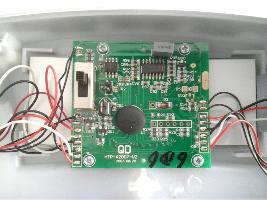
![]()
This lack-luster PCB contains a COB microcontroller with a small 24C02 EEPROM an an LM324 quad op amp. On the left there's some kind of voltage reference and a bit of discrete circuitry I'll have to look at later, but together with R90 it'll be dedicated to generating the excitation voltage and temperature compensation for the load cells.
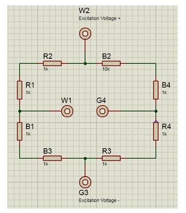
Usually load cells come as 4-wire wheatstone bridges like this one:
![]()
but the ones seen here are wired differently. They behave like potentiometers turned to 50% - give or take a few parts per million.
![]()
Measuring the voltages reveals how they are connected:
R 2.720V <-> R 2.720V
W 3.598V W 1.841V
B 2.720V B 0.961V
| |
B 2.720V B 0.961V
W 1.840V W 0.082V
R 0.961V <-> R 0.960V
So the bridge is being excited with 3.6V from the reference and same sign outputs are connected together. The bridge output is at 1.84V and the 82mV on the low end feeding into 47R (R90) suggest the excitation is at 1.7mA (0.85mA per cell) which seems legit.
The cells will again be connected in this fashion when hooked up to an HX711 front end breakout. We'll have to check out what the manufacturer did on the temperature compensation side of things - maybe it's really just R90.
automated gardening - reservoir infrastructure
Building Reservoirs and Weighing Water for level gauging and flow metering.