-
Thoughts on AFSR + Future!
08/21/2014 at 06:32 • 0 commentsCheck out the video overview we made about the entire project:
I began this project at the beginning of summer not even having a clue how to go about it. I just kept trying and figuring it out. It has been a lot of fun, what a great learning experience. Now I can build robots with gears and more complicated pieces, w00t!
![]()
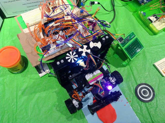
The robot was well received by older adults at Maker Faire Ottawa. There were also some kids who liked it, because they want it to slice the crusts off bread.
In the future, I want to explore two more places that this robot touches on: heating and the digitization of food.
Read more for the thoughts on this.
1) Heating food
This is the larger goal for this project. If we can heat food as it is sliced, would the transfer of heat be more efficient than a skillet or microwave? What if it could be powered by a solar panel?
Interesting questions to investigate.
2) Digitization of food
If you think about it, we do not really digitize our food (to quantify the data) that we eat very well. Usually it has to be done manually, and typing in each meal can become a boring task.
We can use the augmented reality tracking idea, combined with computer vision blob detection, to determine the size of the food.
If we add sensors to the end effector to detect when it touches the plate, then the z-axis encoder could count how far it has traveled, resulting in the thickness of the food.
What other ways can we figure out what food is being cut? We could use AI to assist in the prediction of what is being sliced given the time of day (ie, you’re most likely not eating steak in the morning).
Perhaps there could be a capacitance sensor as well. With all of these data points, it would be neat to try to train a program to suggest various food products that could be cut.
The future will be really fun.
I’m not sure what my plans for the future of AFSR are just yet.
The robot could be vastly improved if there were more powerful motors. The ones we are using are just ones we found in our box. Need more money. :\
If you have been following the progress of the robot, thanks a bunch!
Until next time,Be kind to robots!
-EK -
Automatic Food Slicer Robot: In Action!
08/13/2014 at 22:23 • 0 commentsWe have made some great progress on the AFSR!
Watch this video to see all the updates:
It was an exciting moment a few nights ago when we were able to slice our very first piece of food. (Video)
We will be showing AFSR at Maker Faire Ottawa. If you are around, come out to see it! :D
Stay tuned for more details and photos of the development of AFSR. We’ll be writing more about it after Maker Faire. The deadline for the contest is soon, quite exciting!
-
Test End-Effector, App, and AR Experiment
07/25/2014 at 05:30 • 0 commentsIn this update we wanted to test the Z-Axis by creating an example end-effector sub-assembly. We used a toothpick as an example tool.
We also created an app to interface with the robot and control it.
Finally, we experimented with AR marker tracking.
Read more for all the details and photos!
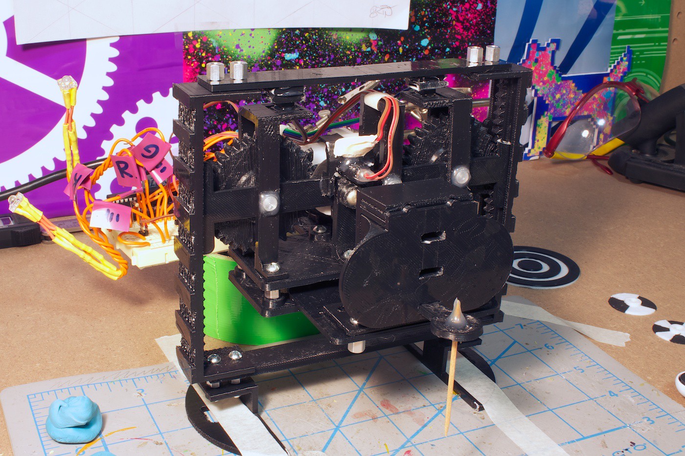
Current Design
Front view:
![]()
Angle view:
![]()
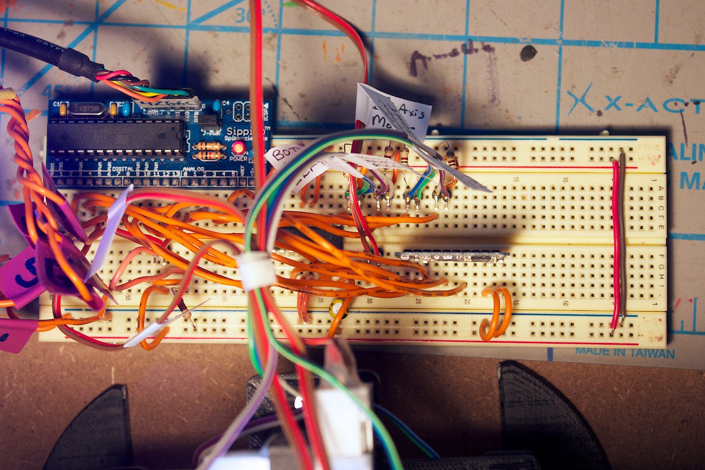
Overhead breadboard:
![]()
Video
Since there are lots of visual demos in this update, we created a video for it. Check it out!
Test End-Effector
Before diving in to designing and printing the Y-Axis slicer, we wanted to see how well the Z-Axis can work by poking sticky tack with a toothpick.
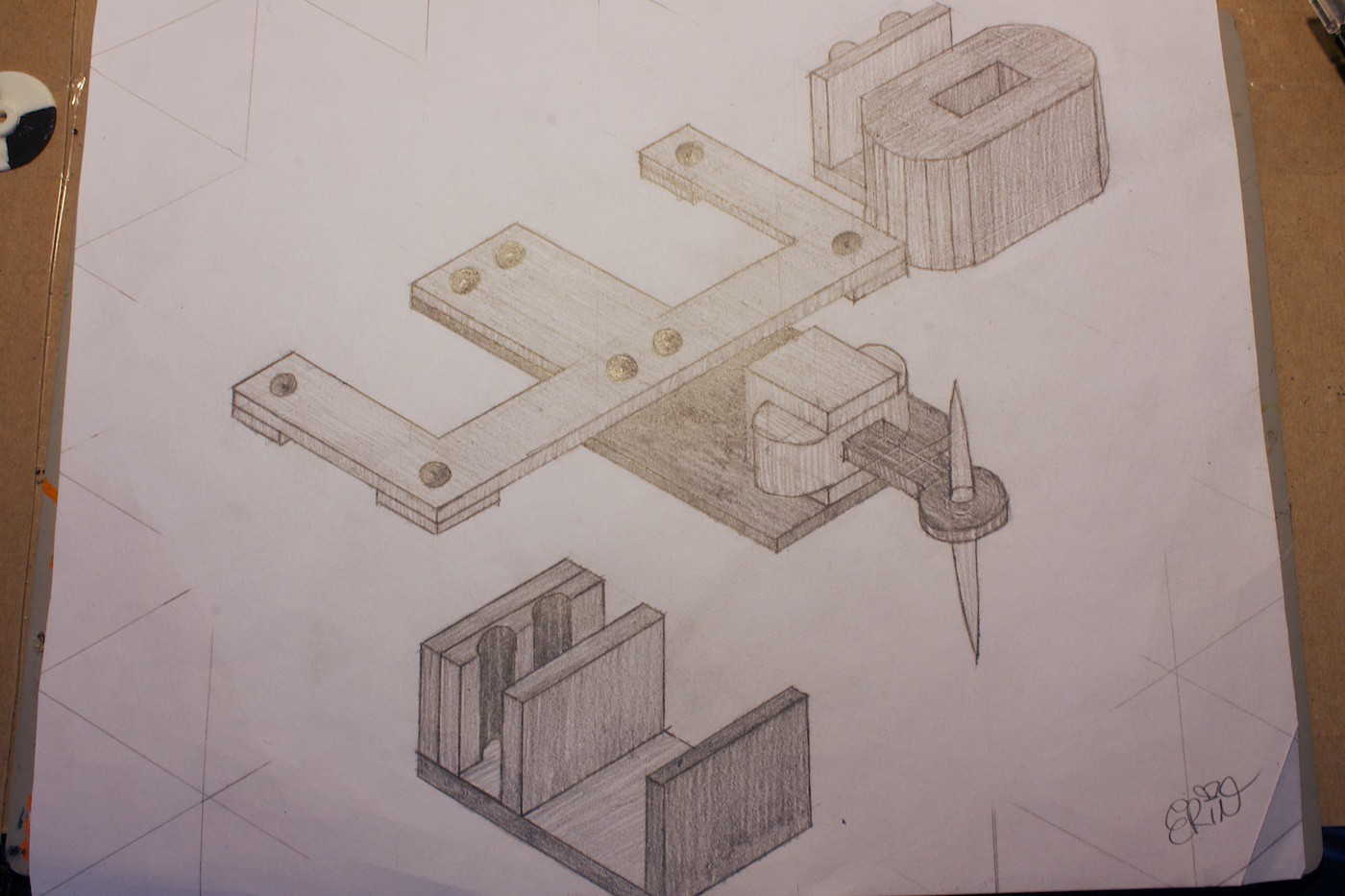
We headed to the drawing board:
![]()
Then designed it in CAD and 3D printed it.
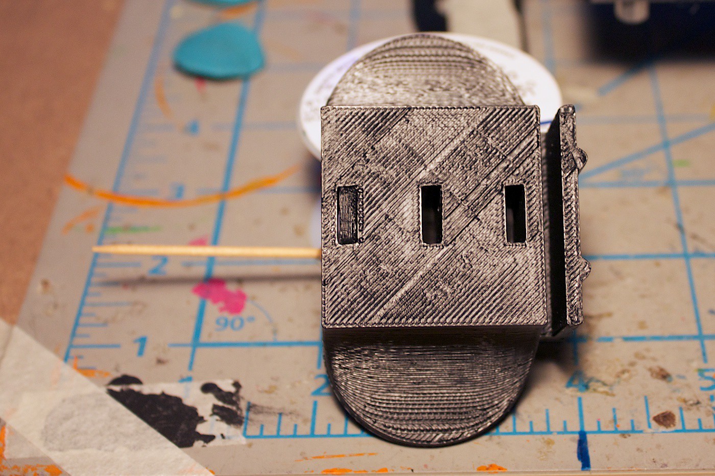
Here is the main tool piece. This interlocks with a tool holder, mounted on a plate attached to the bottom of the gear set on the Z-Axis.
![]()
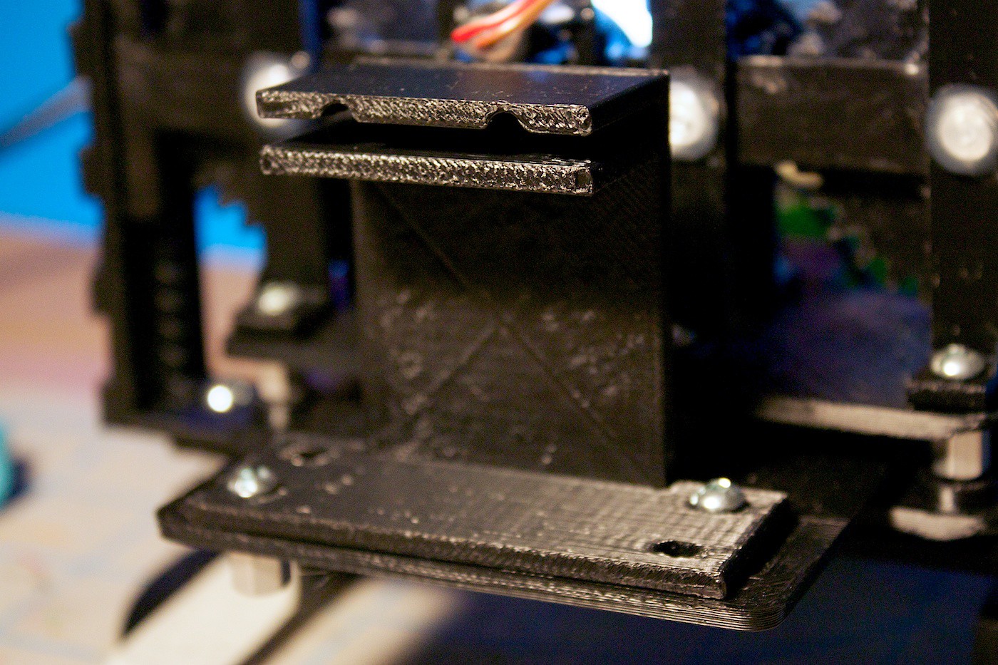
Tool holder piece:
![]()
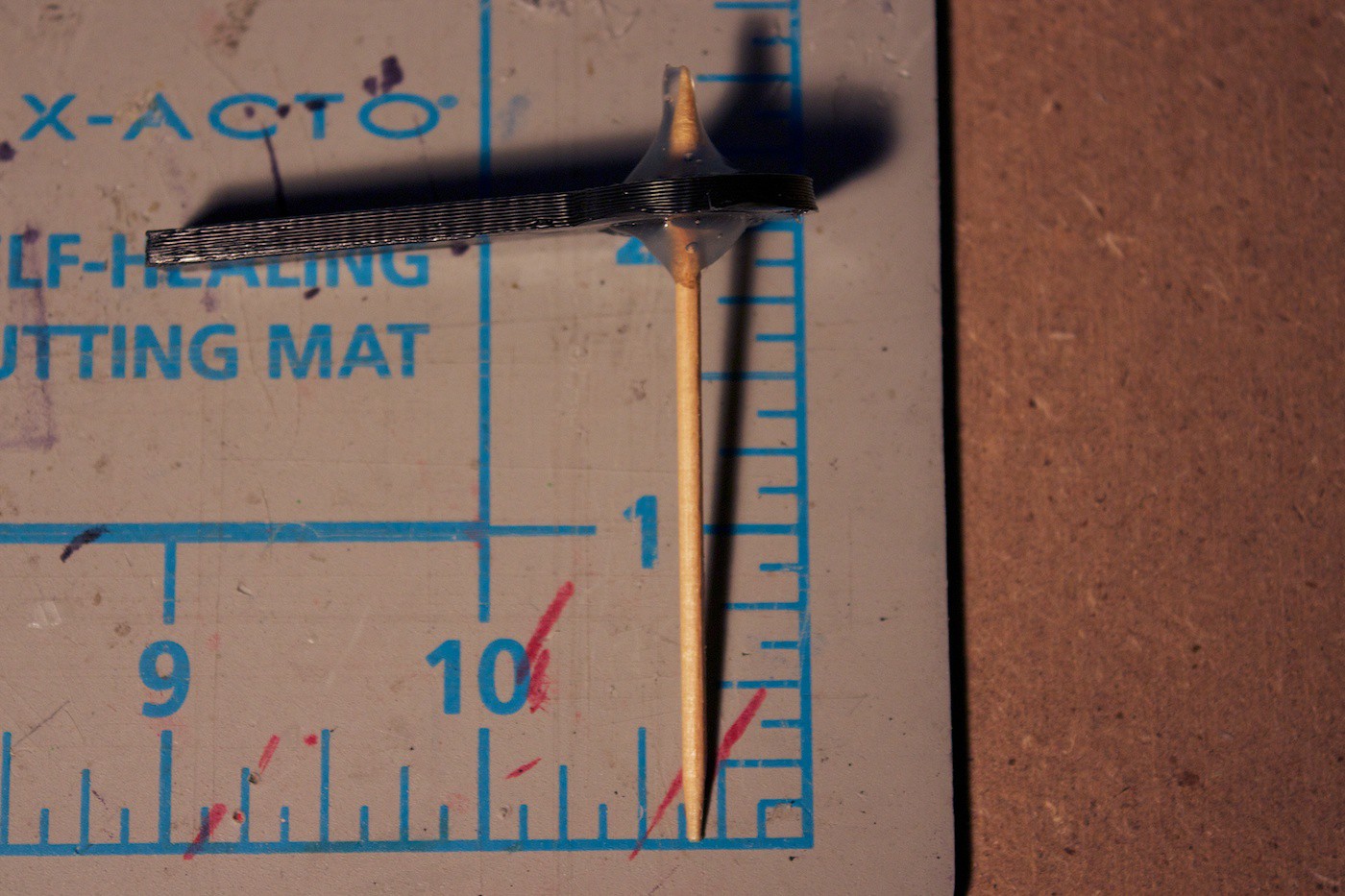
This toothpick holder piece is inserted into the main tool piece. Eventually there will be more pieces similar to this, but designed for other tools / cutlery.
![]()
App
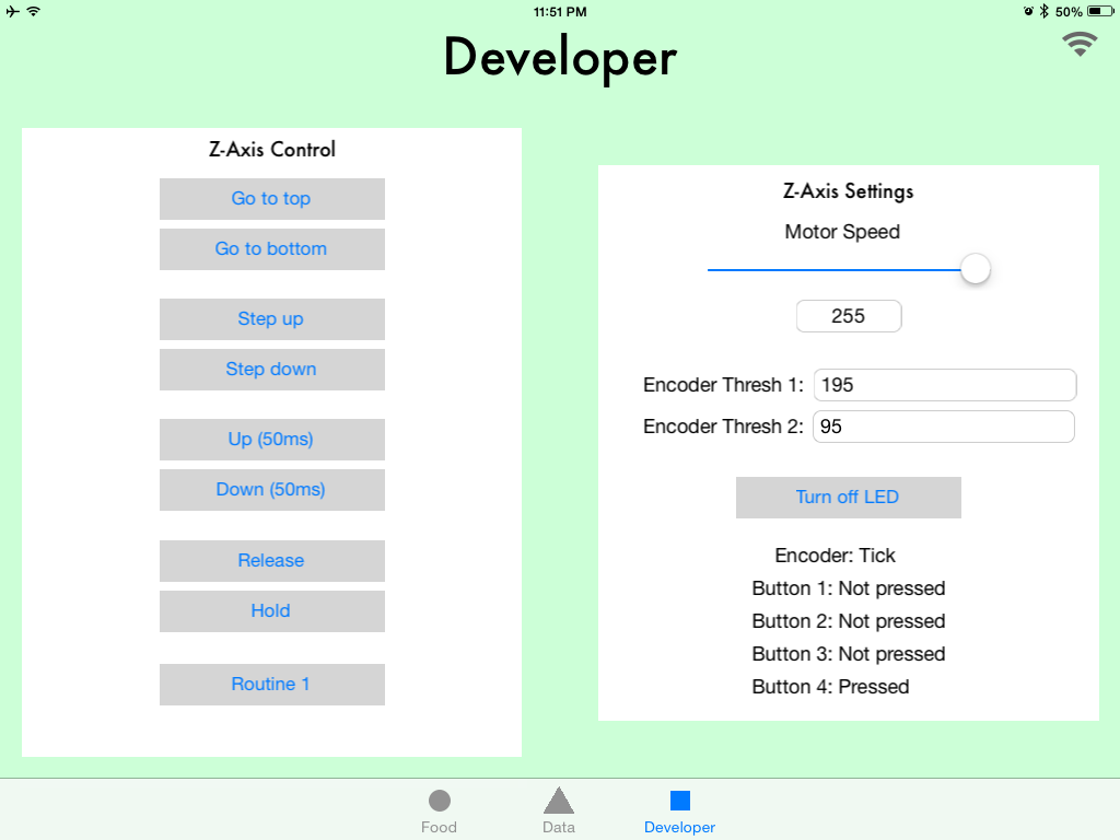
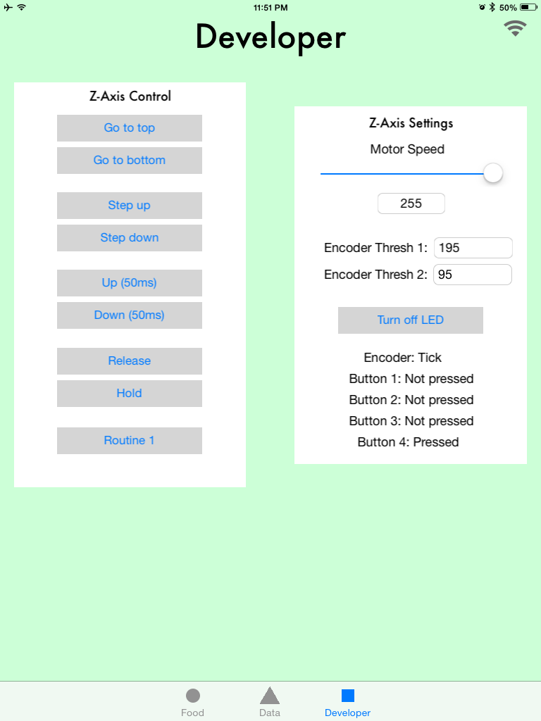
The app has three tabs: Food, Data, and Developers. For this update, we are focusing on the Developers tab. This is where we can control the robot.
On the Developers tab there are two sections: one for controlling the Z-Axis, and another for its settings and status updates.
The settings such as motor speed and encoder thresholds are transmit from the robot to the app when it is connected.
The app is designed to work on iPad. The robot connects to the app on launch using Bluetooth low energy. We are using the nRF8001 breakout board from Adafruit. We send the data back and forth in a protocol we designed called Promulgate.
Also, a small design detail, we made sure the auto-layout constraints were set to display the interface properly in both landscape and portrait orientations.
In the future we envision the Food tab to display some meal ideas based on the history of food you have sliced. The Data tab will use APIs online to grab nutritional information about the food, and chart your frequency of food slicing.
Augmented Reality Experiment
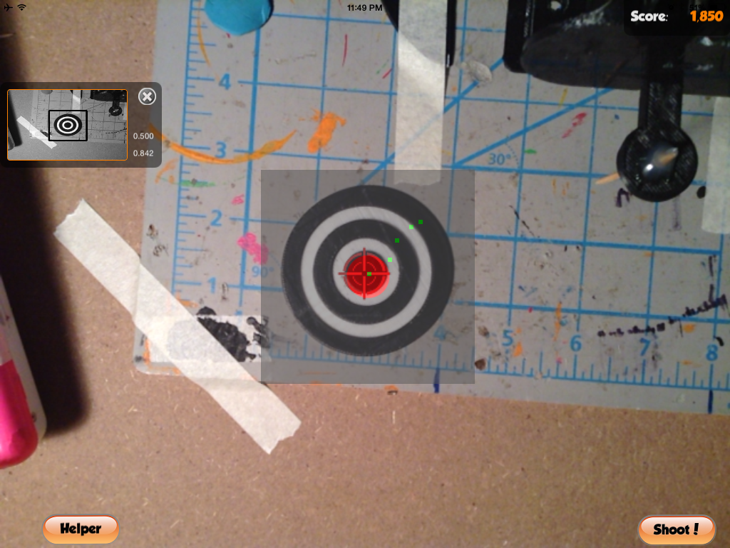
For being able to detect where the food is on the plate, we will need some sort of way to see it. We could use AR markers to detect the corners of the plate, and calculate the distances of the swiped slices from there.
The first step was to get an AR test running. We followed a tutorial based for iPhone, and made some tweaks to the code to make it work with iPad. Instead of printing the marker on paper, we 3D printed it.
Here you can see the app tracking the marker:
In a future update we want to be able to track two of these markers.
Future
That is all for this update. There are so many more things to do…
Ongoing
- Create rails for the bottom of the Z-axis
- Attach a laser pointer to show where the toothpick will be aiming
- Test to see if an IR distance sensor would be able to detect how far / close the food is
- Create the Y-axis slicer sub-assembly
- Experiment with ways to attach a knife to the end-effector
- Make the breadboard more permanent
- Improve routine state machine code
- Modify the nRF8001 advertising name to Food Slicer
App
- Improve connection code and initial loading of data
- Add accessibility data to the buttons
- Work on the Food tab
- Work on the Data tab
- Persist settings data
AR
- Try to make it detect two markers
- Work on calculating the distance from the two markers given their pixel locations and dimensions
- Be able to draw a line on the screen
- Calculate this line’s distance from the markers (to be used with the robot)
Heating Element
- Figure out how to make one! I have no idea! :)
(And most likely many more todo items)
Lessons Learning!
Not exactly past tense this time- but future & present!
My friend Chris Tacklind sent me a box full of laser levels (thanks Chris)! There are actually reflective sensor pairs in some of these, which can be used for better encoders. We are working on tearing them down and trying to use the parts. Stay tuned for the teardown photos in an upcoming update.
At the local makerspace, my friend Tim Brown spent the entire night teaching me about inductors and how to use an oscilloscope. This was very valuable (thanks Tim)! The only problem is that the scope blew up (stopped working) right after. So I have to fix it to use it again… but at least now I have a better idea on how to use one! :)
Hope you enjoyed the video update. Gotta blast and do more hacking! Until next time!
-
Demos: Robot Party & Hammock Talks at Studio Y
07/23/2014 at 02:56 • 0 commentsJust a quick update talking about two hangouts that we demonstrated the AFSR on! (Also includes a special sneak peek)
![]()
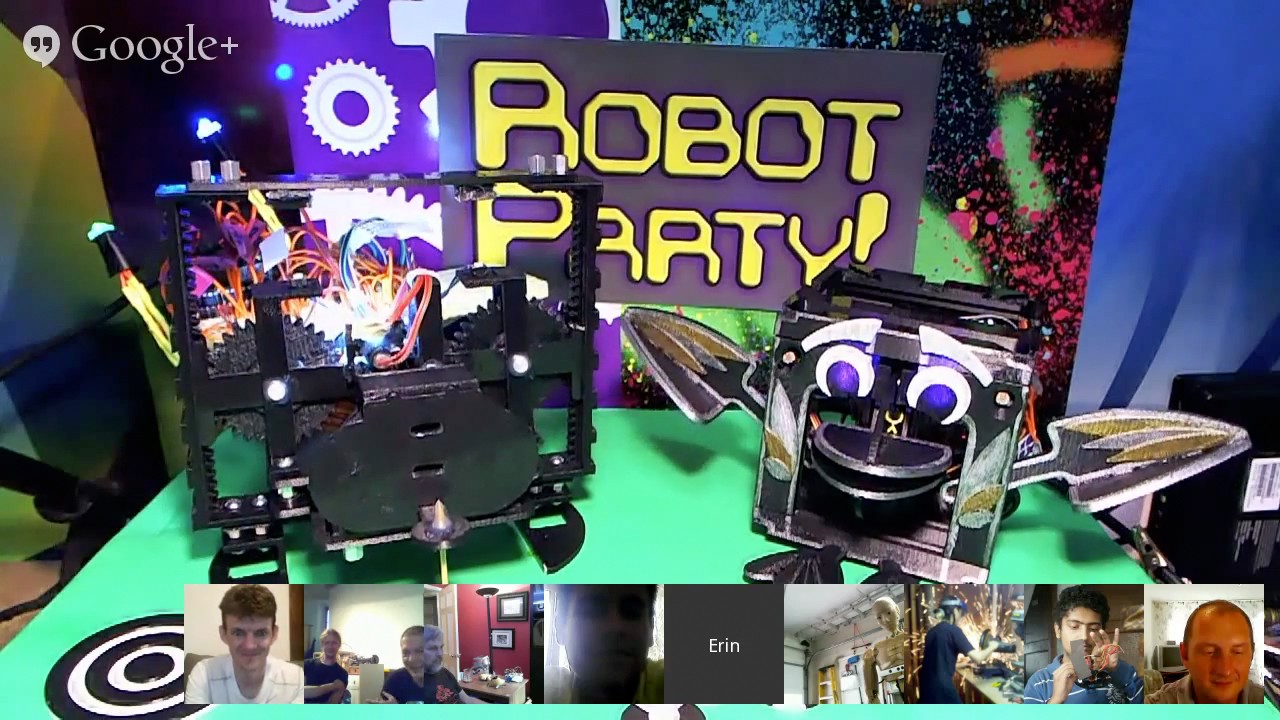
Robot Party
We recently showed the AFSR at the Robot Party on Saturday (July 19th), near the end of the hangout. Check out the video recording of it, we show our project at 1:39:16.
The Robot Party is a Google+ hangout where robot builders from all around the world can show their robot. I started it many years ago, before hangouts existed, and we had to use Ustream and communicate via IRC chat.
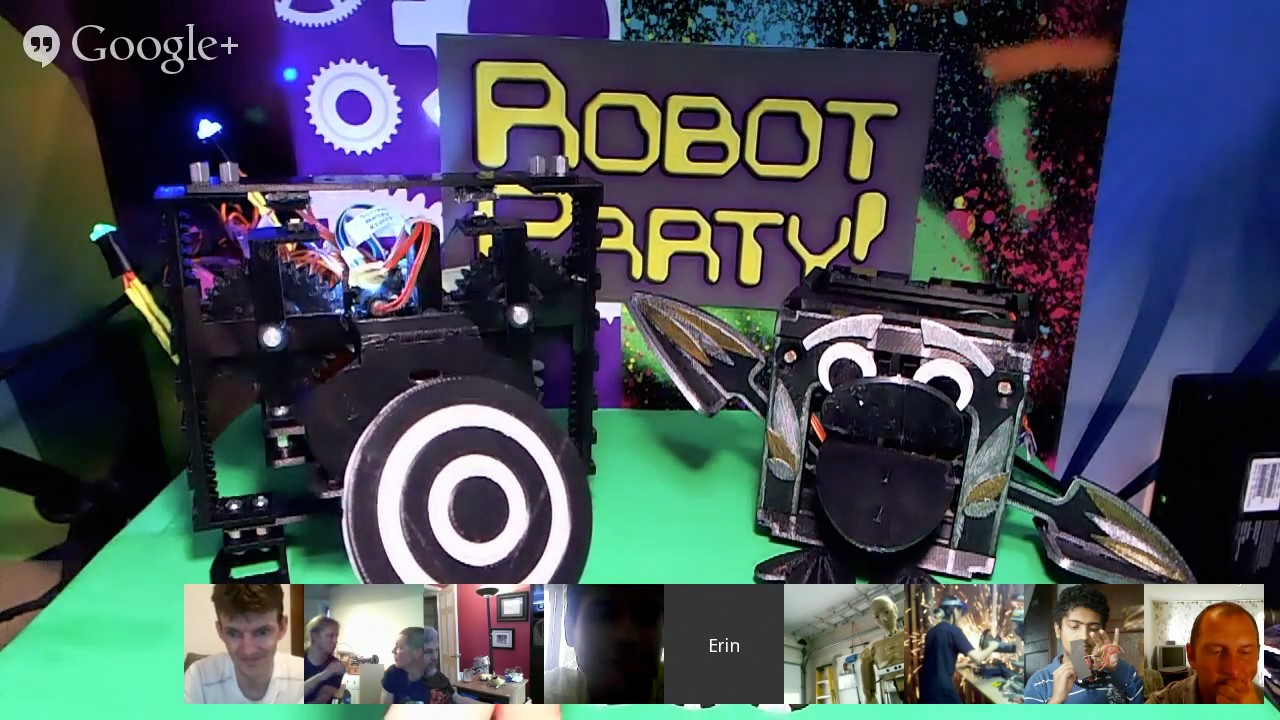
Sneak peek! Here I was showing the AR marker that we might be using in the project.
![]()
The Robot Party is a great way to learn about what other robots people are building! If you’re interested in it, join the Robot Party Rockstars group.
Studio Y
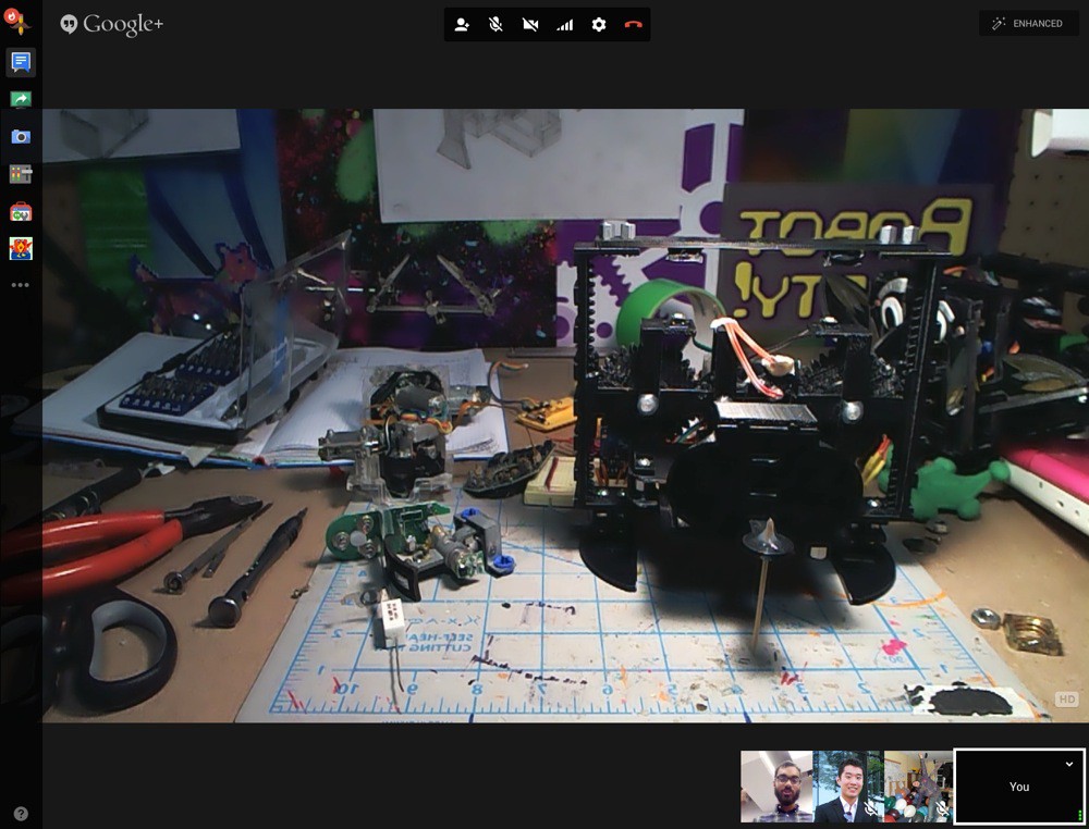
Tonight (July 22nd), we showed the AFSR to 'movers and makers' at Studio Y via a Google+ Hangout.
Studio Y is a group of young people (around my age) who want to drive positive change in their communities. They meet at the MaRS Discovery District in Toronto. MaRS is a large entrepreneurship centre in Canada.
![]()
It was great to hear the questions they had about my robots. Also cool to hear what they were hacking on.
Special thanks to Asad (@asad_ch) for the speaker invitation!
Future
There is another event coming up soon where we can demo the AFSR. This one will be in person, so it will be exciting to see how people will look at the robot and what their thoughts will be.
Really looking forward to this next event- it will be like a ‘demo day’ of sorts.
More updates coming soon. The robot has progressed quite a bit since the last update, but we’re working on putting the finishing touches on it before a new update!
We also received a box full of laser levels that we are dissecting (thanks Chris for sending them). They have a reflective sensor pair that might be useful for the encoder hack. And of course, there is also the lasers themselves :)
Stay tuned for more updates coming soon!
-
Z-Axis Carriage Progress (Part 3)
07/13/2014 at 17:23 • 0 commentsIn this update we continued to work on the encoder- coming up with code to move its position by a given number of ticks.
We also added buttons to detect when the gear set hits the ends.
The most challenging part of this update was figuring out that the motor was overshooting the encoder by 1-2 ticks, and trying to fix this.
Read more to see all of our prototyping.
Current Design
‘Slow-mo’ encoder control:
In action:
Front view:
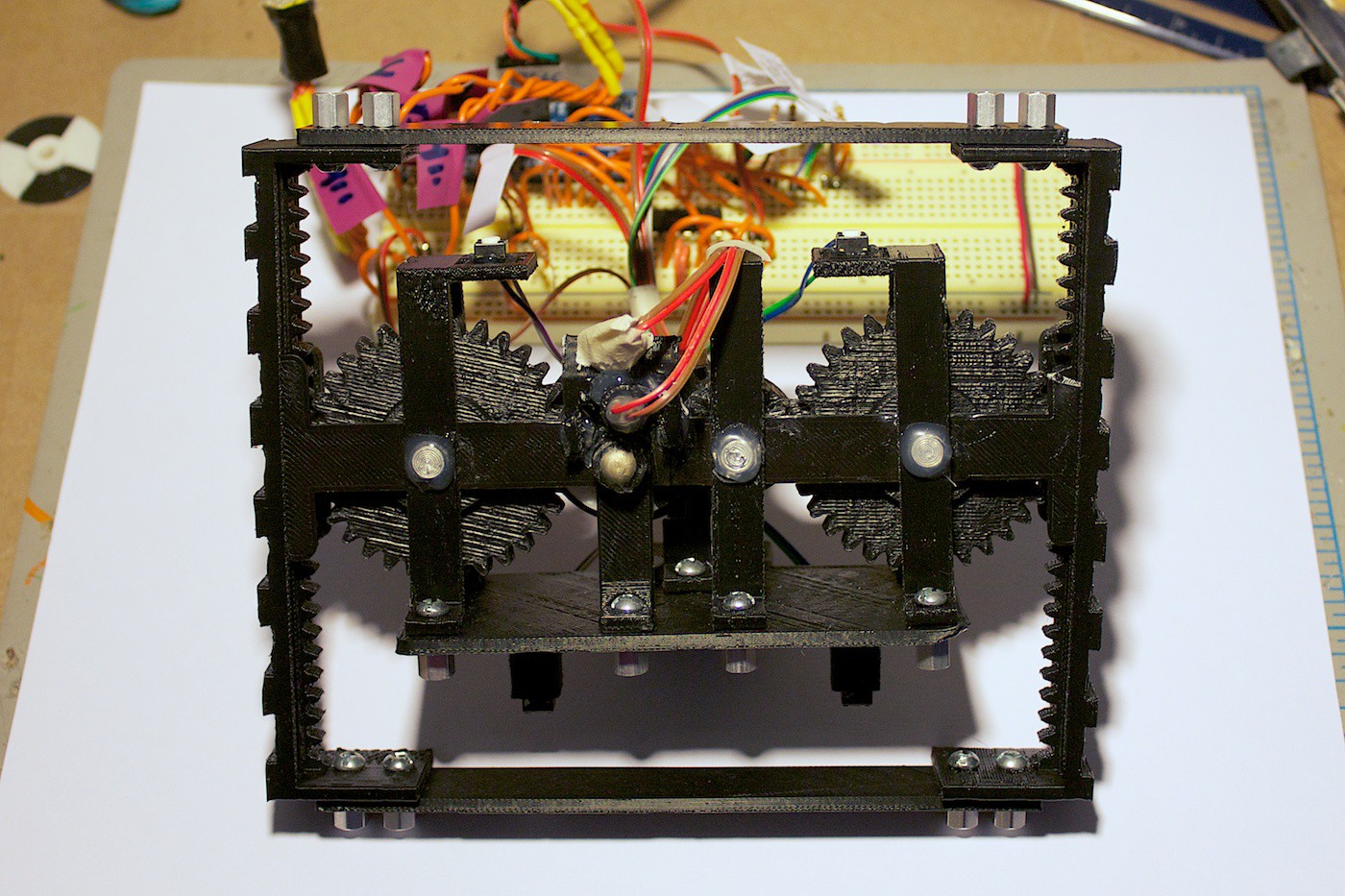
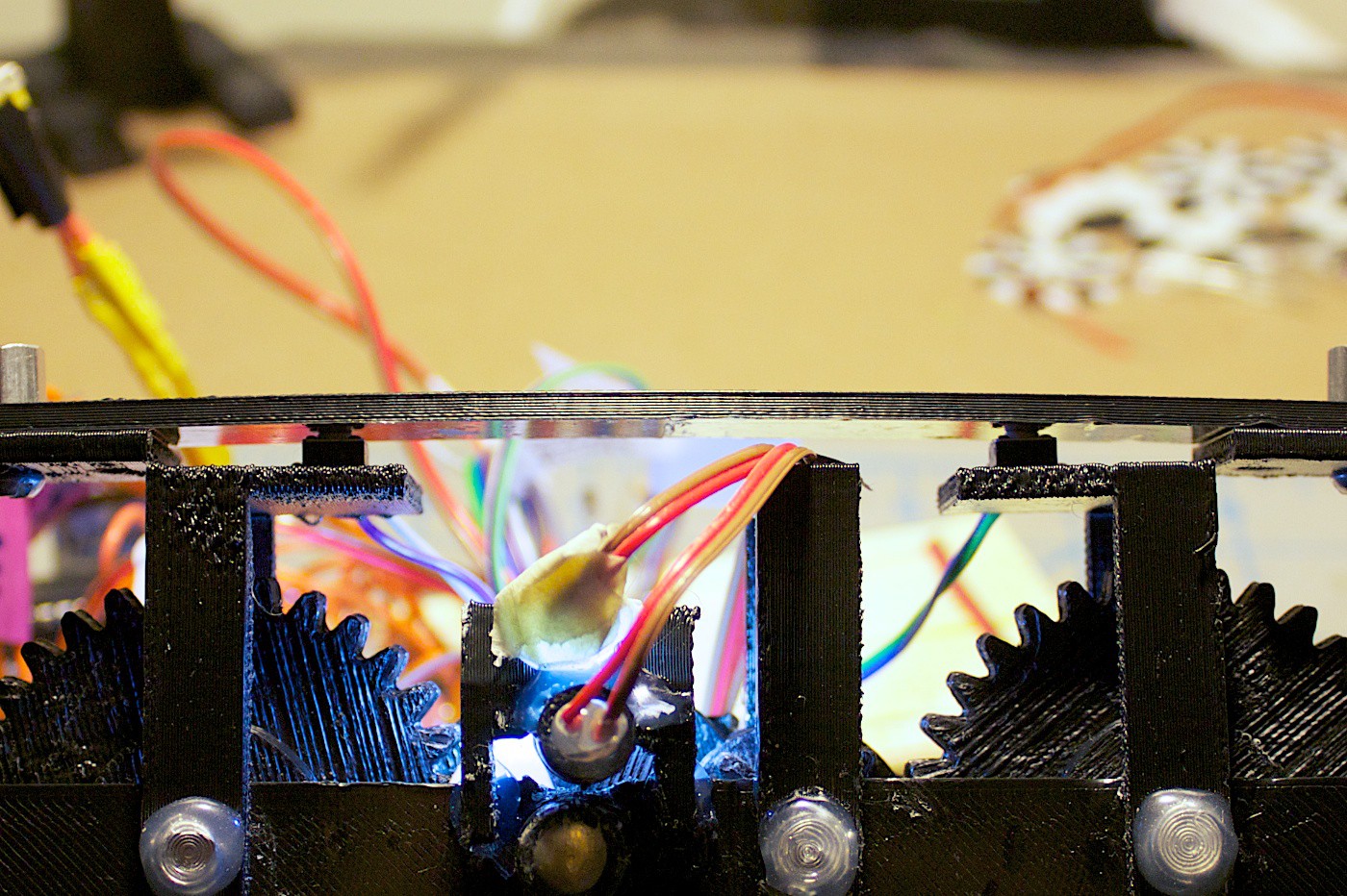
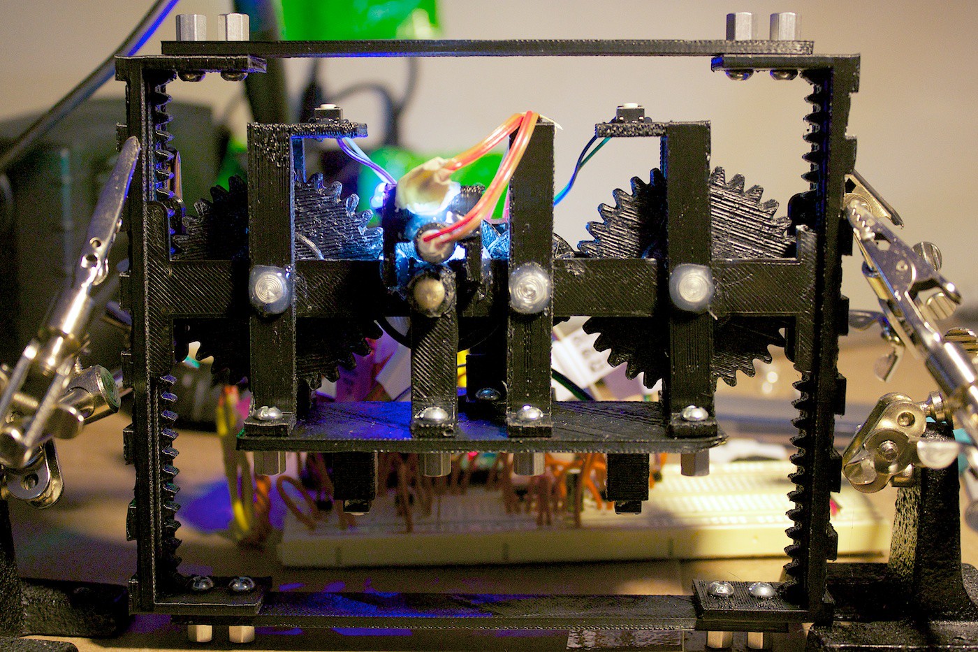
![]()
Side view:
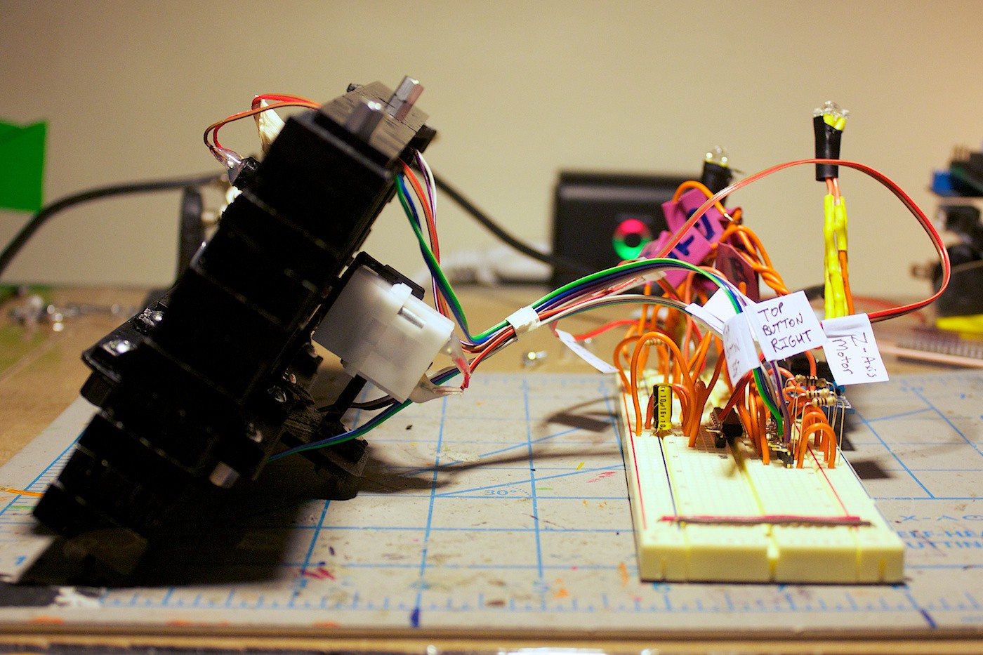
![]()
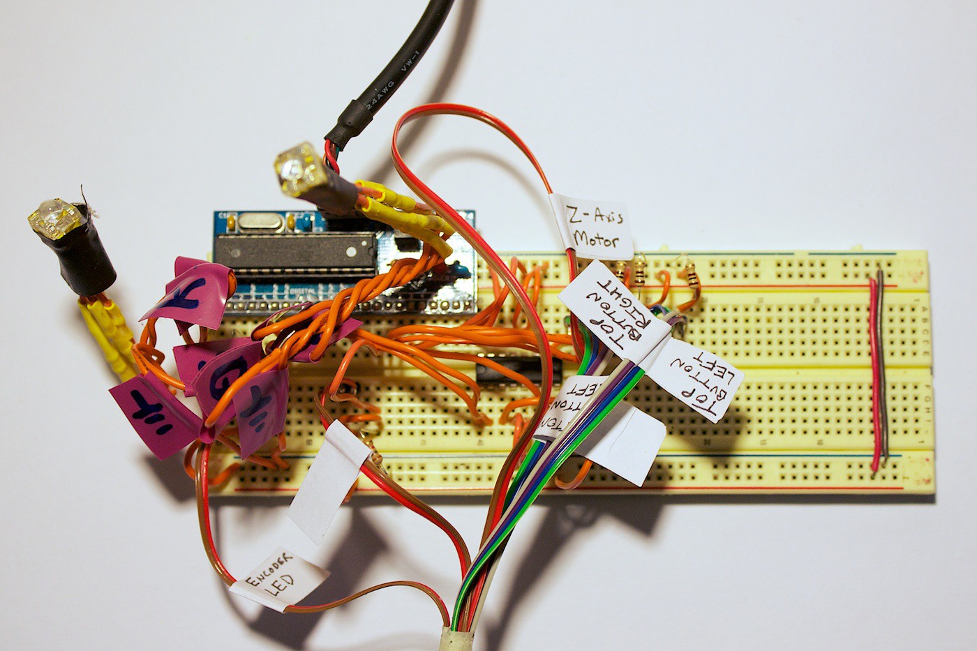
Breadboard view:
![]()
Materials
Mechanical
• 3D printed pieces in ABS plastic
• 18x 6-32 3/8” screws
• 18x 6-32 1/4" stand offs
• 4x 1”, 1/4" diameter Rivets
• Hot glue
Electronics
• 1x Sippino Arduino derivative
• 1x Breadboard
• 1x 10uF capacitor
• 6x 68 ohm resistor
• 2x 150 ohm resistor
• 5x 100 ohm resistor
• 1x 1k ohm resistor
• 2x RGB LED
• 1x White 5mm LED
• 1x Photocell
• 4x Tactile buttons
• 1x LM293D
• 1x 120:1 DC gear motor (Reason for choosing this one is it is what we had on hand.)
• Wires and labels
DIY Encoder Part 2
Now that the LDR can detect changes from the dark/light stripes on the encoder disk, it was time to write this into code.
The first tactic we went with was a moving average filter on the LDR. The previous value was compared with the current to see if it exceeded a threshold.
This code did not work entirely well. Sometimes it would skip ticks on the encoder. This was mainly due to the size of the moving average.
After tinkering with this for about 30 minutes, suddenly it all stopped working. The threshold was no longer the right amount. However, nothing in the environment changed. The ambient light was the same, the white LED was still on, and nothing had moved.
… Or has something moved?
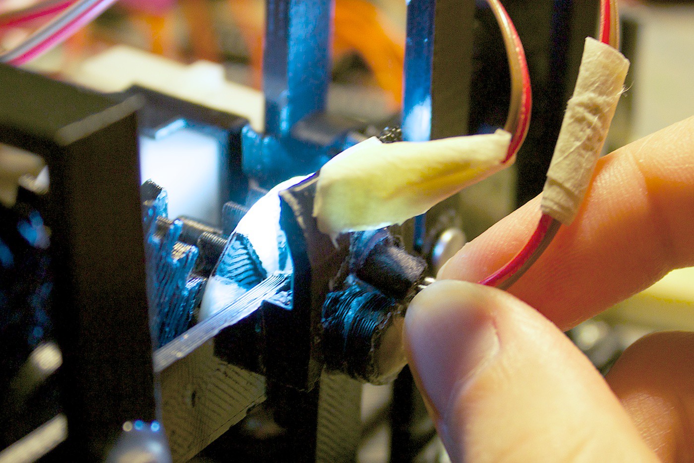
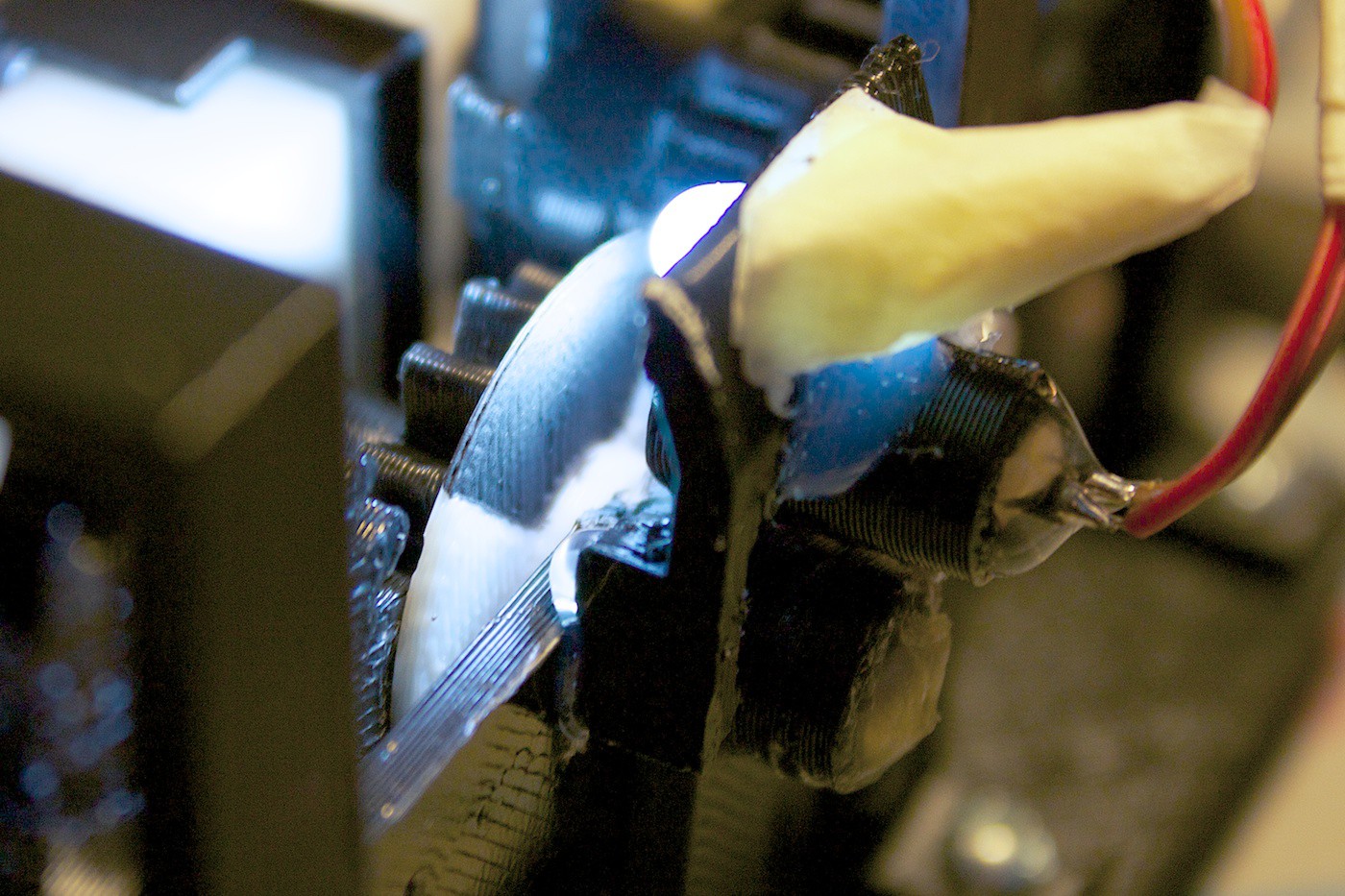
The LDR was currently attached to the mount via a piece of paper wrapped around it and hot glue. The paper was ripping away from the glue, causing the LDR’s angle to move.
Here you can see us pulling at it:
![]()
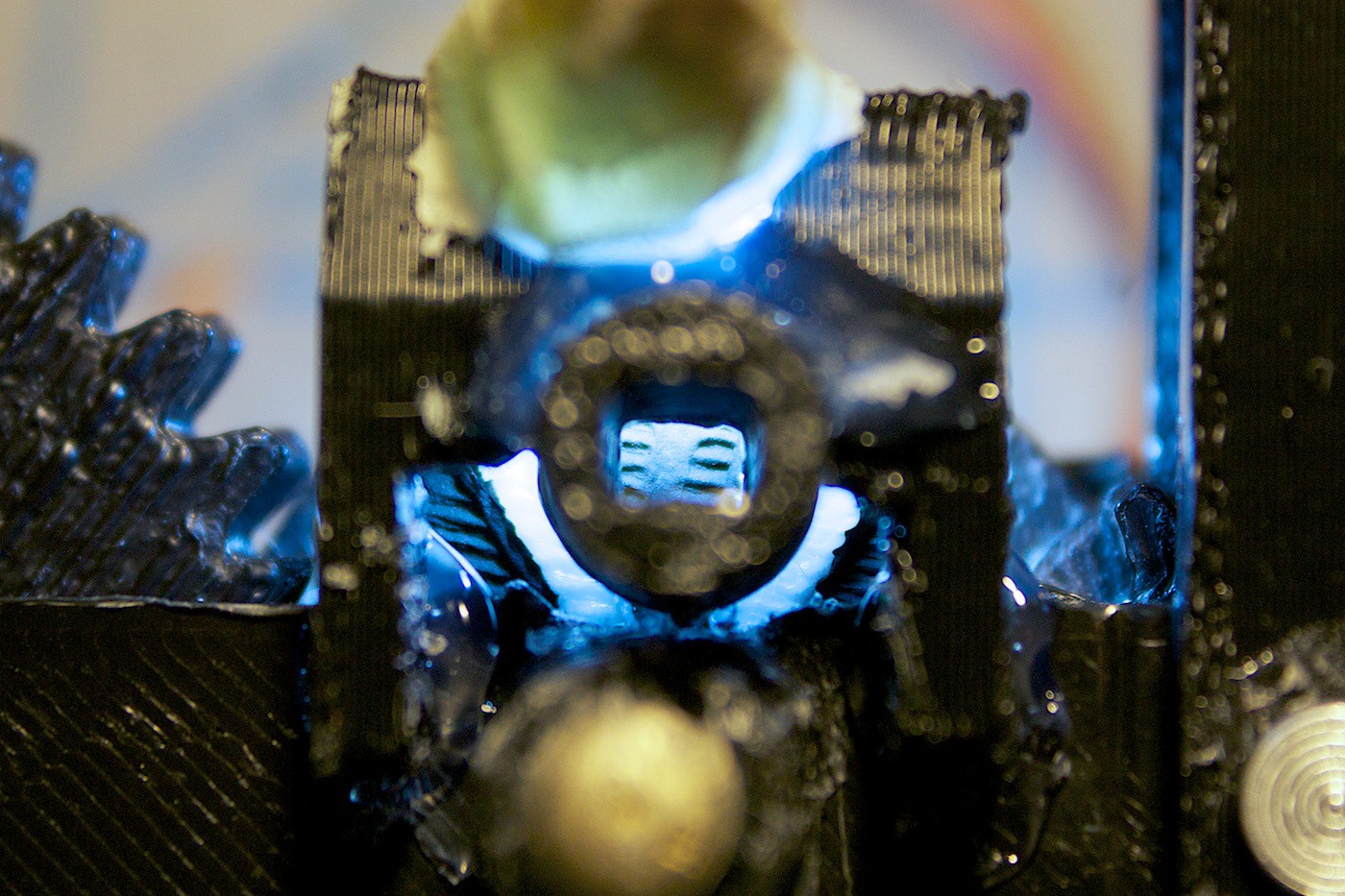
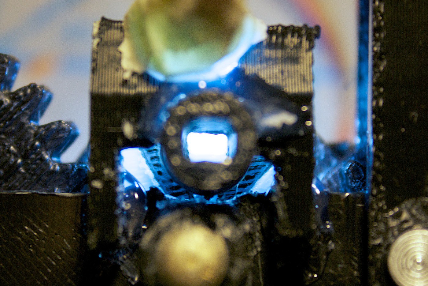
We designed and 3D printed a tube for the LDR.
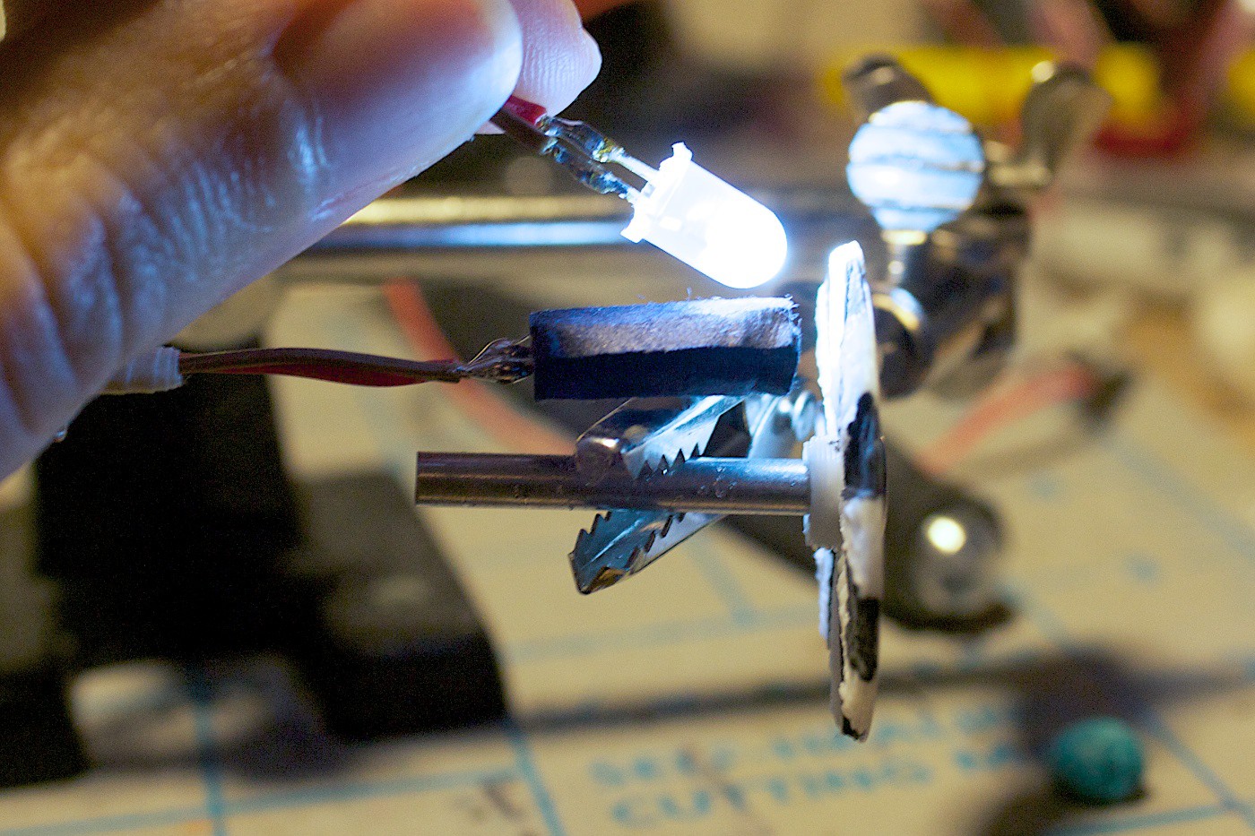
We find the next two photos so cool. It is looking through this tube to see what the LDR sees. Imagine if your vision was an array of these? Woah.
Dark:
![]()
Light:
![]()
Adding the LDR to this tube helped with the stability. The threshold remained the same. But there is still the problem with skipping the encoder ticks remaining to be solved…
DIY Encoder Part 3
If we told the motor to turn 6 ticks, it would always overshoot by 1-2 ticks. It just was not able to stop in time.
At first we tried to tackle this problem in the code. If there wasn’t a ‘tick’ within 50ms, then we would tell the motor to slow down. Otherwise, run at maximum speed all the time.
This did not really work out. The motor would still overshoot. Plus, by telling the motor to slow down, it had less torque to be able to move it up and down the racks.
We worked on this for an embarrassingly long amount of time. We decided to take a break and look at the hardware to see if there was a problem there. The LED and LDR were fine, but maybe what they were pointing at wasn’t? What if the encoder disk was wrong?
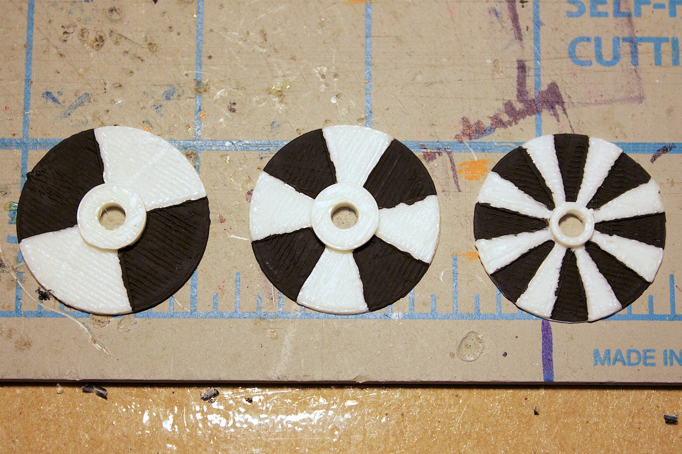
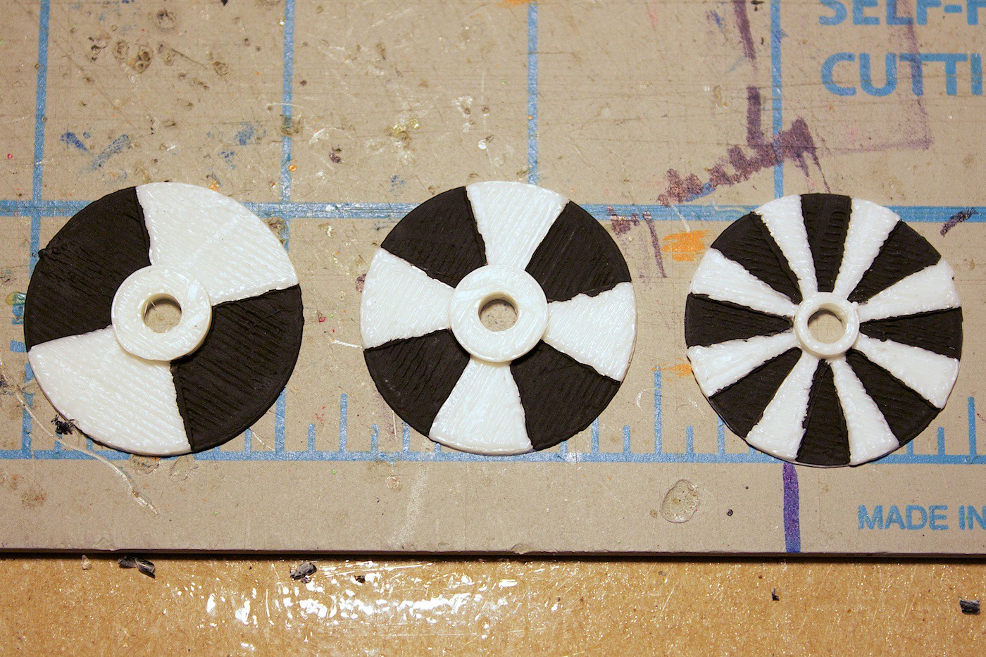
We created two new disks, one with 90 degree ticks, and the other with 45 degree ticks.
![]()
The one we ended up using was the 90 degree ticks disk. It works well with this set up, and is quite reliable.
![]()
We tried a few different code techniques for the 90 degree disk to see what could work the best.
One way was to find the maximum or minimum value starting from the latest tick. If the values started either increasing or decreasing respectively, then we would say that max/min was a tick.
This approach didn’t work out very well in reality. Sometimes it would trigger a tick when there wasn’t one. We guess this is due to some reflections on the disk, like the ridges from the filament strands or something.
The way that we are currently using looks for a specific threshold for the dark and light stripes – without a moving average. If it hits it, and the previous tick was the opposite shade, then it is considered a tick.
This works well most of the time. Sometimes the thresholds have to be re-calibrated. This is either due to some ambient light that the white LED isn’t flushing out, or a new problem that we haven’t become aware of yet.
It is working! Hooray! (And still has not broken yet, to date)
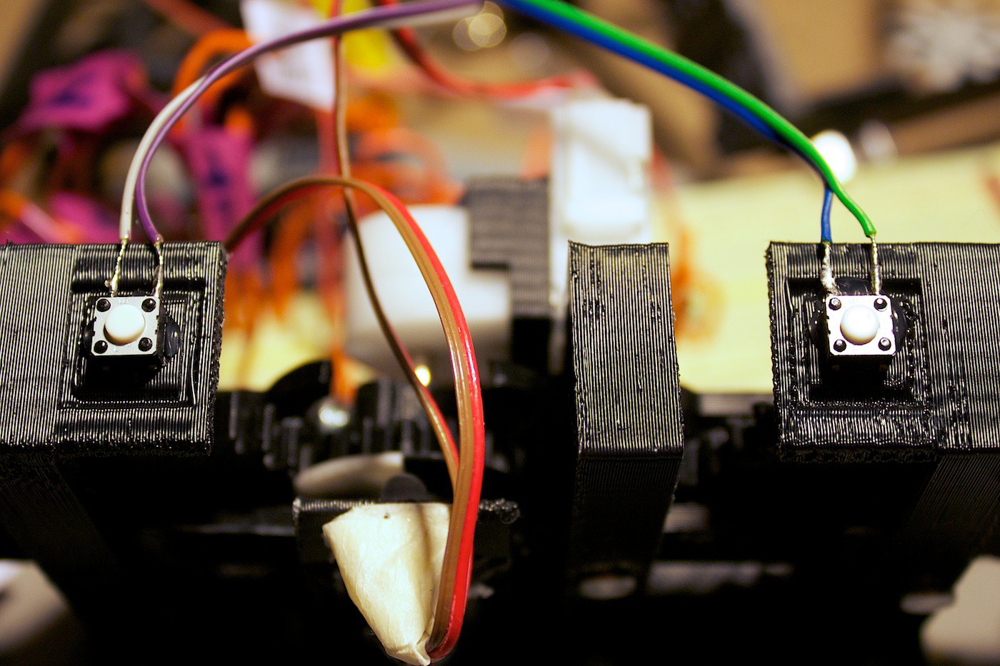
End Stop Buttons
The next addition we wanted to make was to add buttons to the ends of the gear set. The buttons would be triggered when they would hit the ends of the racks – specifically the bars that join the two racks together.
The reason why we need these buttons is in case the motor decides to run away, and keep driving into the end of the racks. It would be bad for the motor and gear set.
The encoder would not be able to prevent such a problem since if the gear set is at the end, then it cannot move any further, making the encoder disk unable to spin to the next tick.
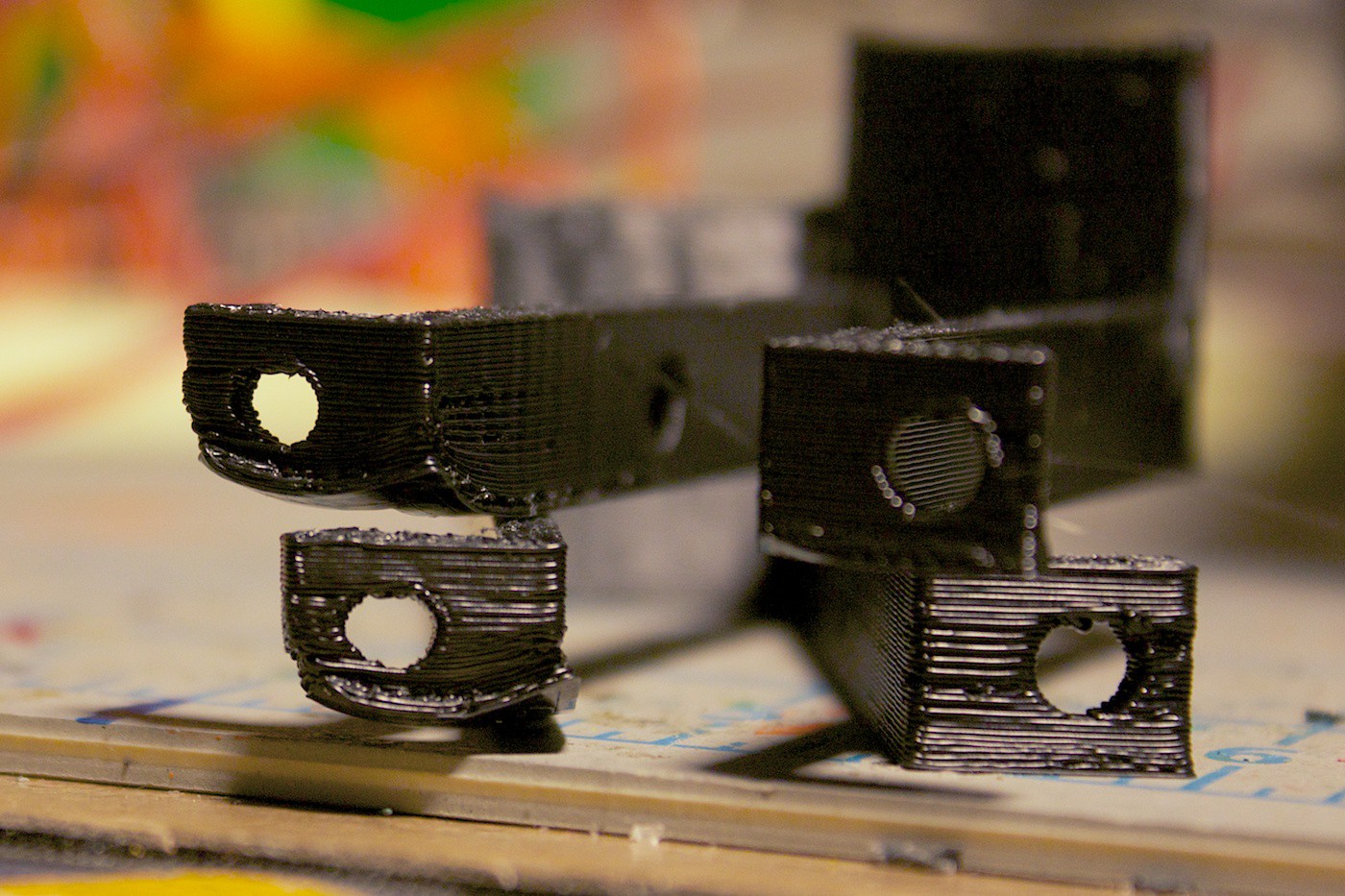
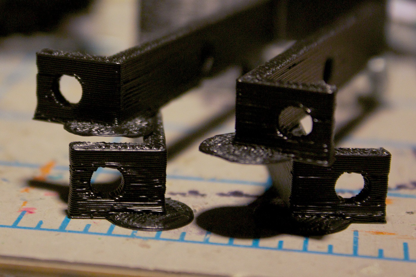
The first step was to design some modifications to the clip that is used to keep the gear set together. Except that we ran into a printing issue:
![]()
The corners on the left tabs are warped. To fix this problem we added little two-layer circles to the corners:
![]()
The buttons were glued on the top of the clips inside of the designated box:
![]()
On the bottom, the buttons were added to pieces to extend the button past the distance where another plate could be attached.
Here is a vine of us testing the buttons:
When assembling it all together, there was a small problem encountered. Sometimes the horizontal bar would flex when the buttons would hit it. It would keep flexing, and not letting the buttons be pressed.
Here you can see quite the flexing:
![]()
This problem was fixed by flipping the bar over (glossy side up).
Now the gear set can move until it hits the buttons, and reverse its direction!
Drive Gear Breaks
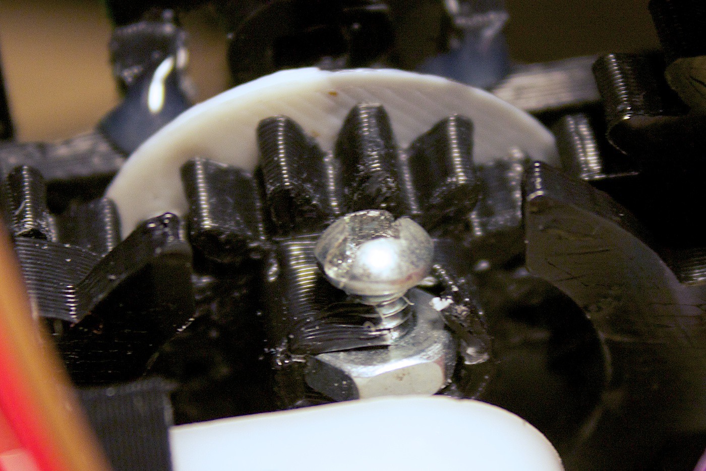
Just as we finished the buttons and watching the gear set move… the drive gear breaks.
![]()
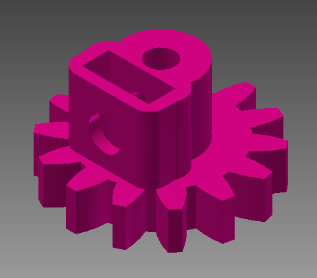
We decided to create a better version. There was quite a bit of wiggle room for the motor’s shaft in this one, so we made it smaller. We also increased the height of the motor mount.
![]()
It was printed in 100% infill, and it is much stronger than the previous version.
Increasing Rack Slider Length
With the buttons added to the gear set, it restricts its movement to approximately 2.7mm. This will not be very adequate to cut food … unless the food is for leprechauns or faeries or something.
We changed the design of the rack sliders to be 30mm longer.
Here is what it looks like now:
![]()
You can see that this lets the gear set move much more:
To finish off, we added encoder control to this movement. It delays a bit of time after each tick, then proceeds. If the buttons are pressed, then it reverses the direction.
It is very nice to see this work after all of the iterating :D
Lessons Learned
Do not assume paper is a stable material for attaching things to.
Sometimes it is nice when things break, because you can fix them in the present moment rather than a larger disaster later on.
The encoder disk fiasco taught us that you have to look at different places, other than what you’re working on, for what the cause of the problem might be. It can suck a lot of time away from your project if you keep trying to fix the problem in one way.
The next item we are working on is a little test sub-assembly to try out an end-effector.
We want to create a piece that attaches to the base of the gear set and extends outwards. On this extension would be a mount for the end effector. The end effector we would try first would be a toothpick.
We are hoping to be able to draw a smiley face on the skin of a fruit by having the Z-axis move up/down, thereby poking the fruit with the toothpick.
It will be interesting to see how superficial the pokes will be. Or maybe it will go right through. We are eager to test the Z-Axis strength to find this out!
This brings us up to date with our current progress. The pieces for the end effectors are printing out right now… Stay tuned for the next update!
-
Z-Axis Carriage Progress (Part 2)
07/13/2014 at 16:57 • 0 commentsWe advanced further into the build of this sub-assembly. Now the Z-Axis can slide along the racks, and we started creating the DIY encoder.
The most challenging part of this update was getting the DIY encoder set up to show different readings for the dark/light stripes.
We also solved the existing rack warping problem.
Read more to see all the details.
Rack Slider
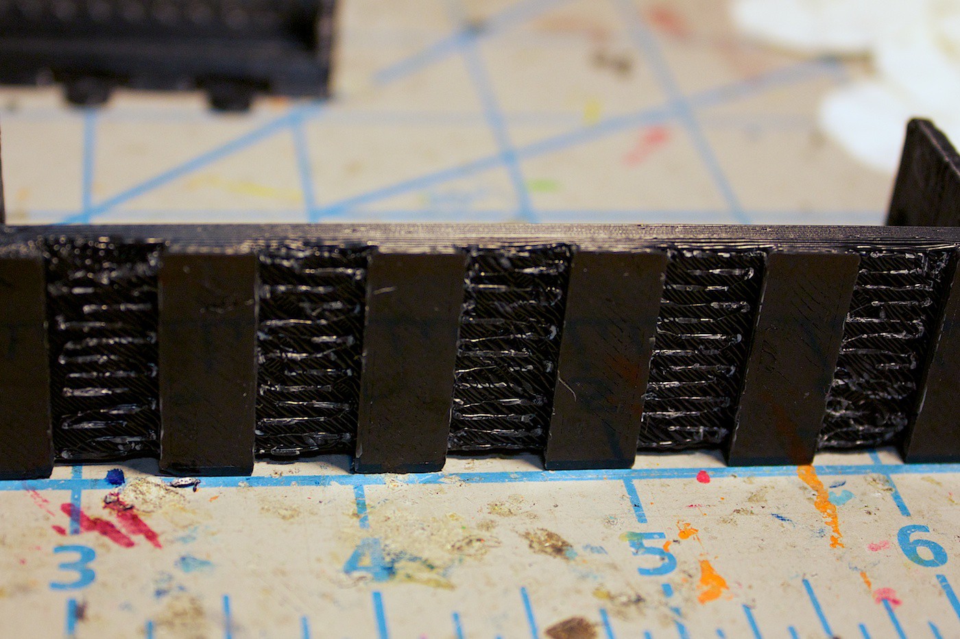
From last update, we noticed the rack slider pieces were warping after being printed. Our first guess at trying to alleviate this problem was to include ‘spaces’ along the bottom of the piece.
The way this design works is by cutting 3mm rectangles into the piece. Another rectangle is nested inside of its outline- but with its length extending beyond. This new rectangle is extruded to be two layers thick. Our 3D printer’s layer thickness is set to 0.3mm.
Since the piece will be printed with supports, the two-layer rectangle helps these supports adhere to something. If we did not have the rectangles the supports have to try to adhere to the build plate, usually resulting in unreliable print results.
Here is how it turned out:
![]()
After removing the piece from the printer, you can remove the two-layer rectangles and clean the supports away.
![]()
This is what the end result looks like. It is no longer warped like our previous piece.
![]()
We then tested the new racks with the gear set, and it works! The gear set no longer gets stuck at the middle, and it can slide smoothly along the entire rack.
Hooray! Another problem solved!
DIY Encoder Intro
The next thing we wanted to make is an encoder. We need to know some sort of position of the gear set along its racks. This feedback is useful both for driving the motor, and in case the gear set starts to slip (imagine if it’s trying to slice a burnt steak).
As it is right now, we are currently using time to drive the motor to certain positions. This can be problematic if an error occurs, such as the motor mount being stripped from the drive gear, or the gears slipping, or the pinion and rack slipping.
An encoder can solve this problem by being able to keep track of how many ‘ticks’ the drive gear has turned. A ‘tick’ is a change from dark to light, or vice-versa.
The way our DIY encoder works is by using a small 3D printed disk, in white filament. Black paint is then added to the alternating grooves. The intervals of the ticks will depend on how well your system works. We found that the most reliable solution was to go with the 4 intervals – each tick is 90 degrees. We’ll discuss how we figured this out later.
![]()
There is a white LED that shines on the disk. The idea being here that it will provide enough light to eliminate the effects of the ambient light.
A light dependent resistor is inside of a tube, pointed at the disk to see if the light is dark or bright.
![]()
The problem with DIY encoders is that it takes a bit of tinkering to get it set up to the point where it is reliable. We had some fun prototyping to find a way that works. Here’s how we did it…
DIY Encoder Part 1
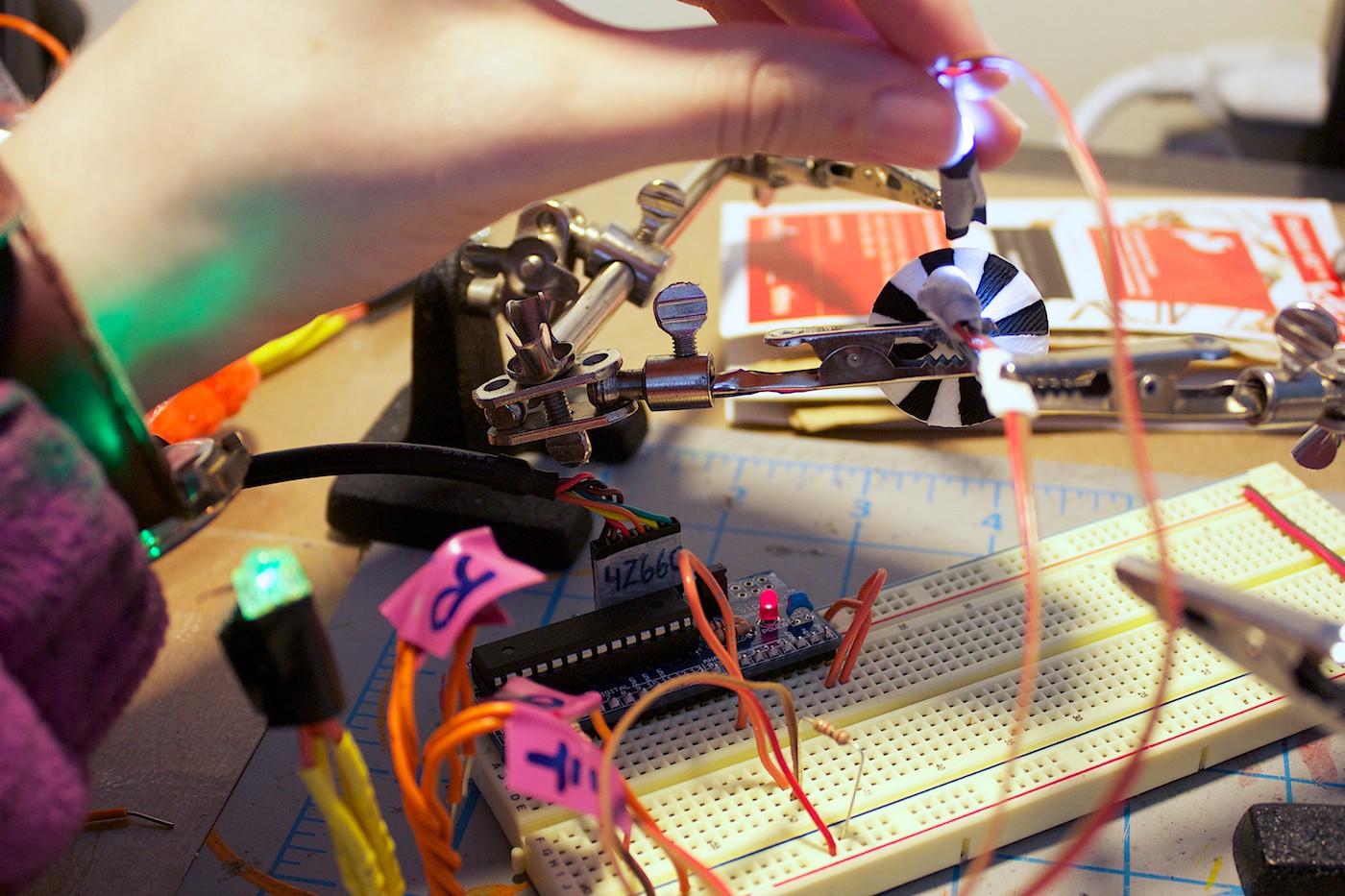
The first step was to set up the encoder disk and LED. We mapped the value of the LDR to the green LED (in the bottom left corner of the photo). By spinning the disk (slowly) and pointing the LDR at it, we could see if the value would change by the green LED getting brighter and dimmer.
![]()
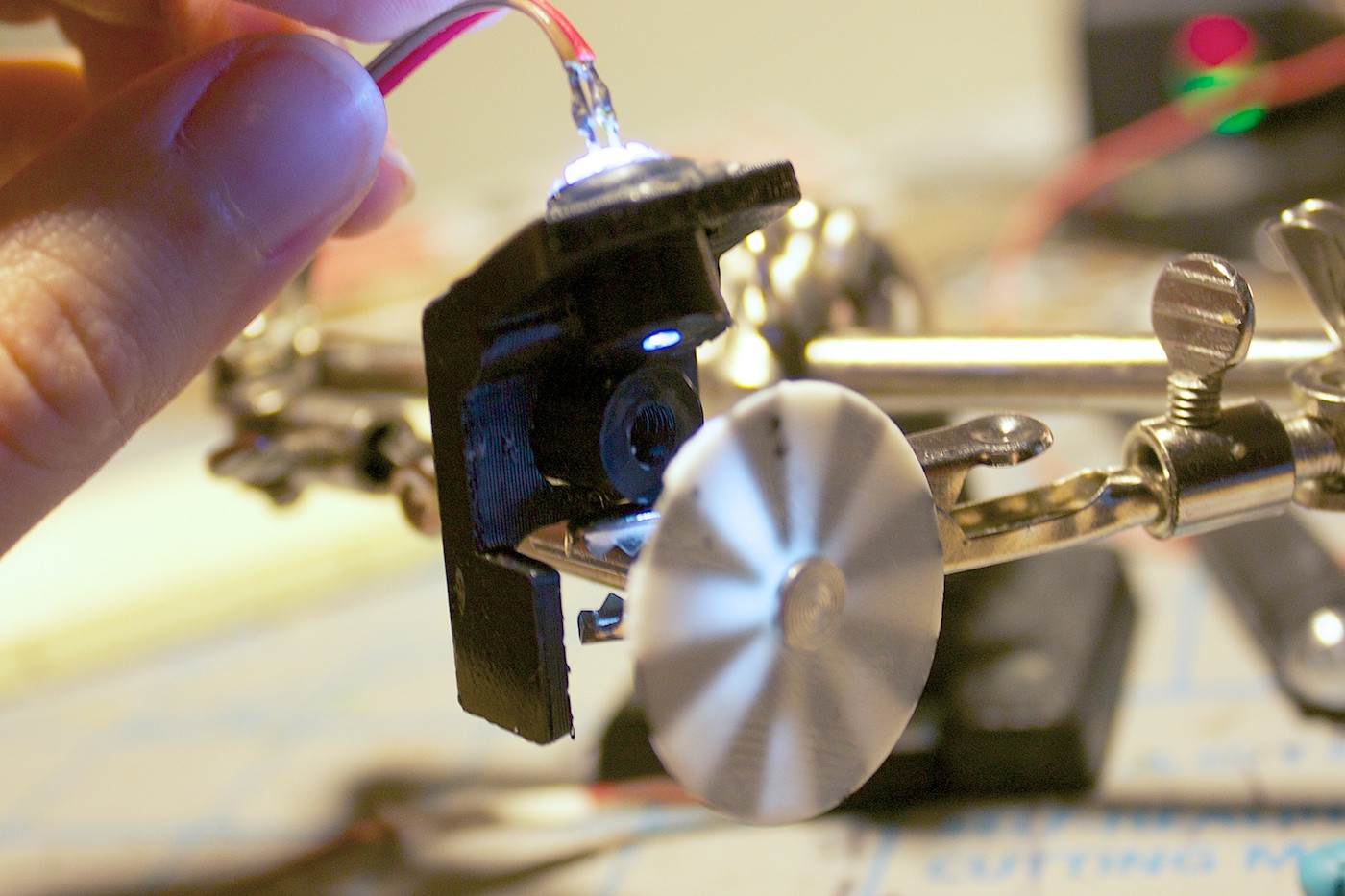
We tested holding the white LED at various angles, and at what distance to hold the LDR. We then designed and printed a mount for these. Here you can also see that we were experimenting with a tube on the white LED to make the light more focused.
![]()
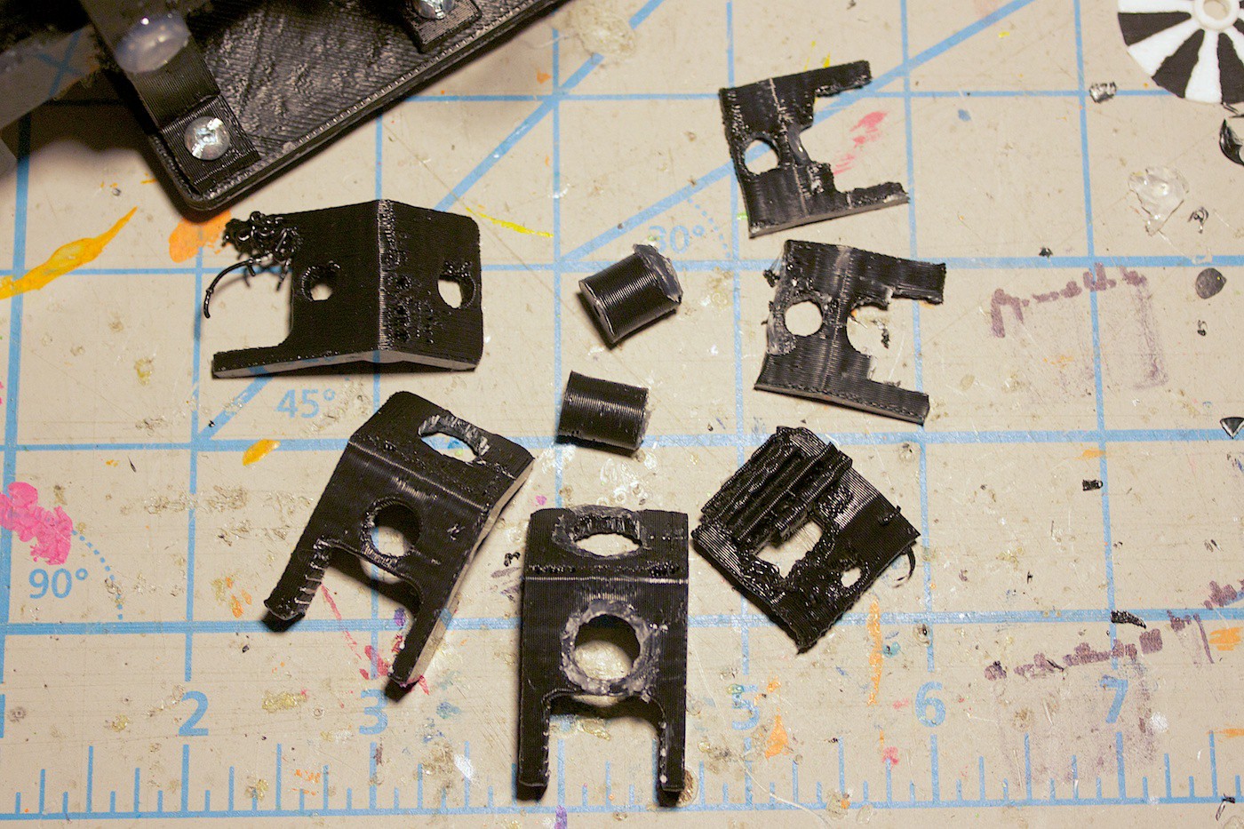
Well, it turned out for the first try we got everything wrong. The tube on the white LED was not needed. The angle of the LED was wrong. The LDR placement was wrong. The mount didn’t attach properly to the bar on the gear set. We went through a lot of iterations…
![]()
…until finally, we made a version that worked! Woot!
![]()
Test in action:
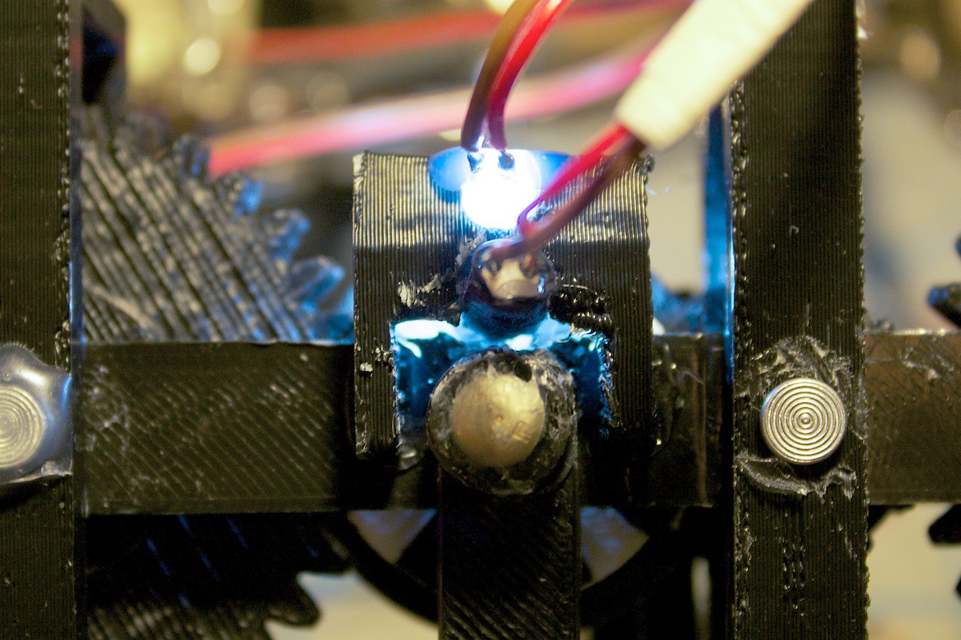
From behind:
![]()
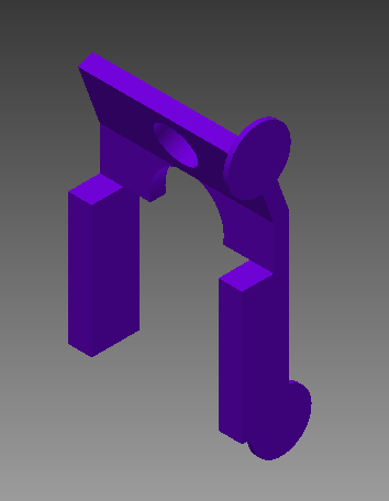
In CAD:
![]()
Next up is to create the code to detect when the encoder is changing, and be able to control the motor.
Lessons Learned
When prototyping, sometimes it might be better to try out two ideas at once, rather than just one. I think the design of the encoder LED mount may have been completed faster and with less hassle, if I was designing and iterating on two different ideas concurrently. This never hit us until now :( … Will keep this in mind for next time.
For a complete list of materials to date and the current view of the Z-Axis, please view the Part 3 update.
In the next update we work on the encoder code progress and add buttons!
-
Z-Axis Carriage Progress
06/25/2014 at 07:27 • 0 commentsFor first step of the robot we decided to start working on is the Z-Axis Carriage sub-assembly.
We ran into some problems along the way, but iterated on the design to get it to its current working state. There are still additional problems remaining to be solved and the feedback system to be implemented.
Read more for our prototyping adventures!
Materials
Pieces are all 3D printed in ABS plastic.
Screws are 6-32 3/8”. Stand offs are used instead of hex nuts because we had more of them on hand.
4x Rivets for the gear spindles. 1” in length and ~1/4” in diameter.
Hot glue is used for keeping the rivets in place, and the motor mount piece attached to the motor.
Motor is a 120:1 gear motor. Reason for choosing this one is it was one that was in my box.
Current Design
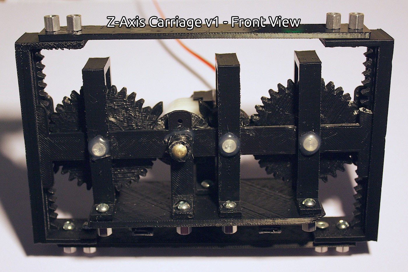
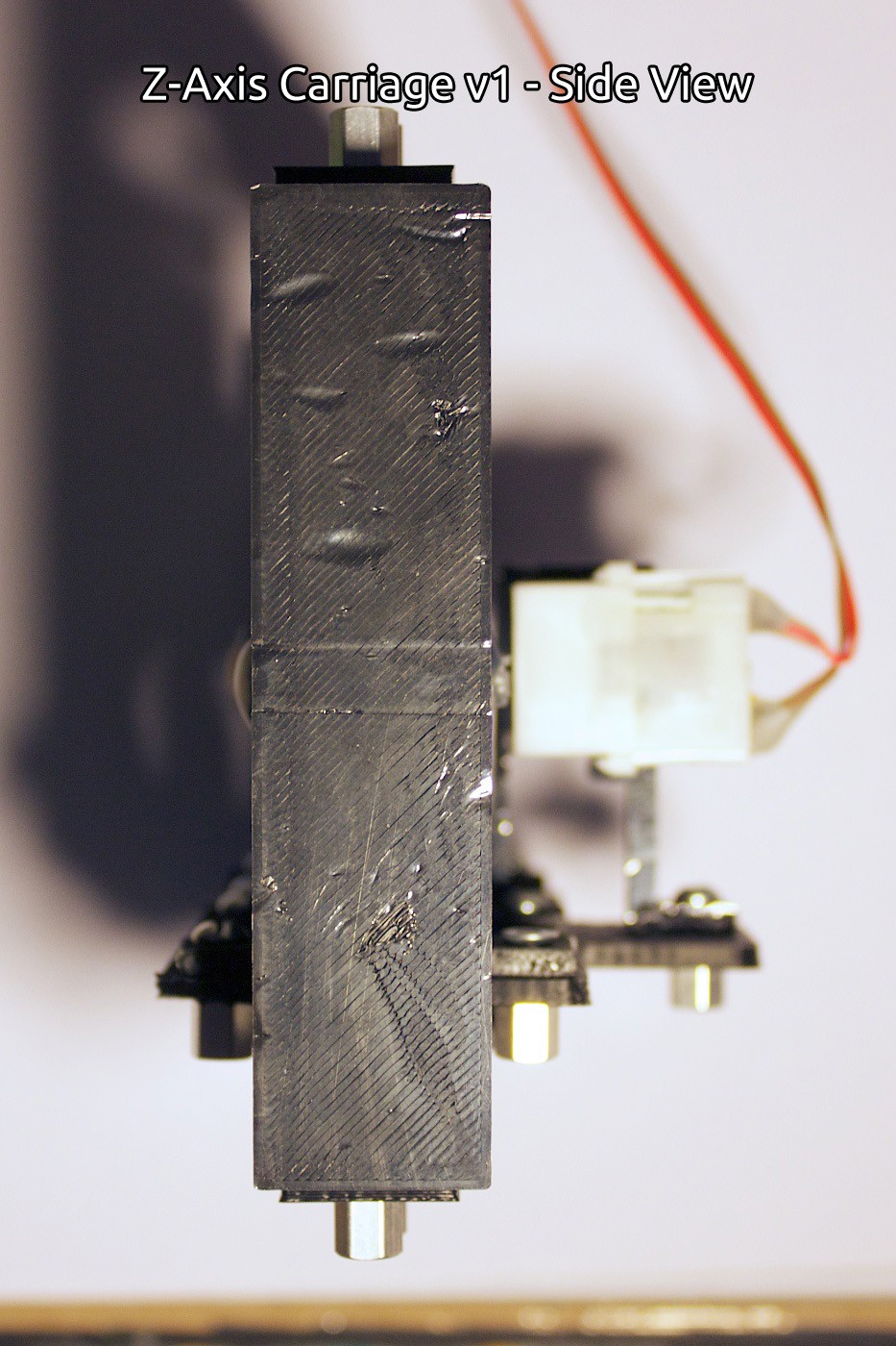
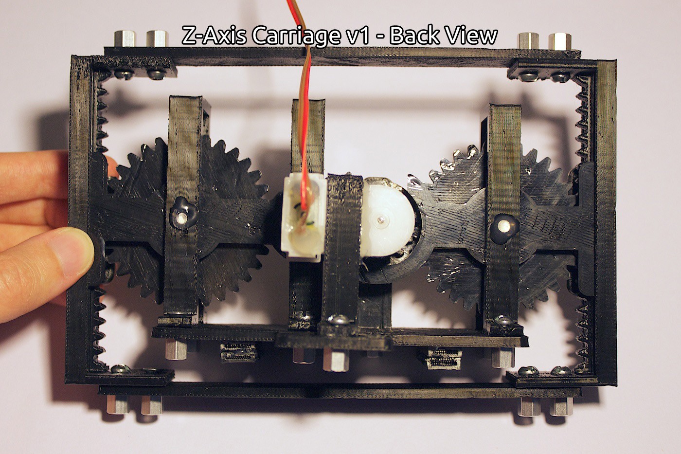
In action:
Front View:
![]()
Side View:
![]()
Back View:
![]()
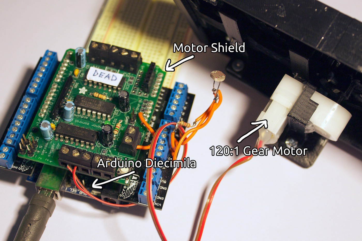
Electronics:
![]()
Prototyping
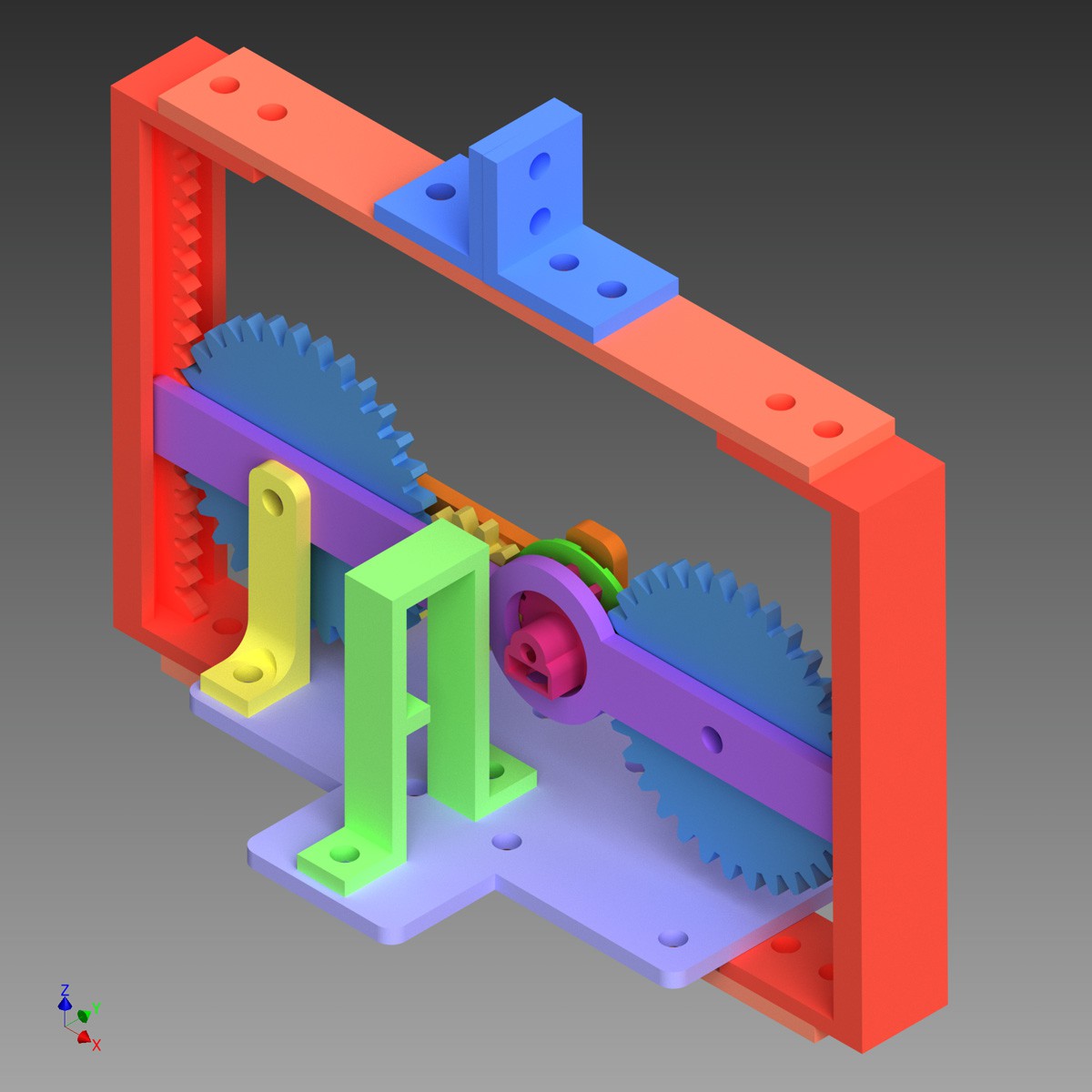
We started out by creating all of the pieces in CAD (Autodesk Inventor) first, based on the drawings.
![]()
We printed the pieces, making some adjustments along the way. Eventually we finally had an assembly put together of the gear set, the inner and outer supporting bars, and the bottom plate.
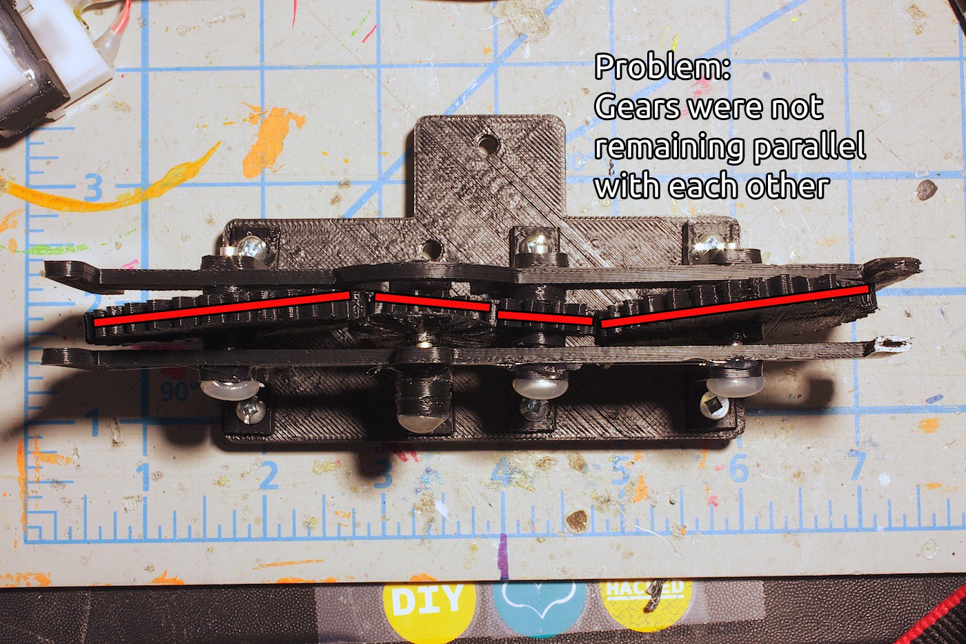
Then we ran into the first problem. The gears kept angling inwards, preventing them from meshing properly.
![]()
We fixed this problem by increasing the diameter of a circle extruded on the top of the gear, and the same idea with the inner bar.
We also made the vertical stands that are holding up the bars and rivets for the gear set into clips. This kept the entire gear set more tightly together.
The gears now stay parallel to each other and no longer tilt wildly out of place!
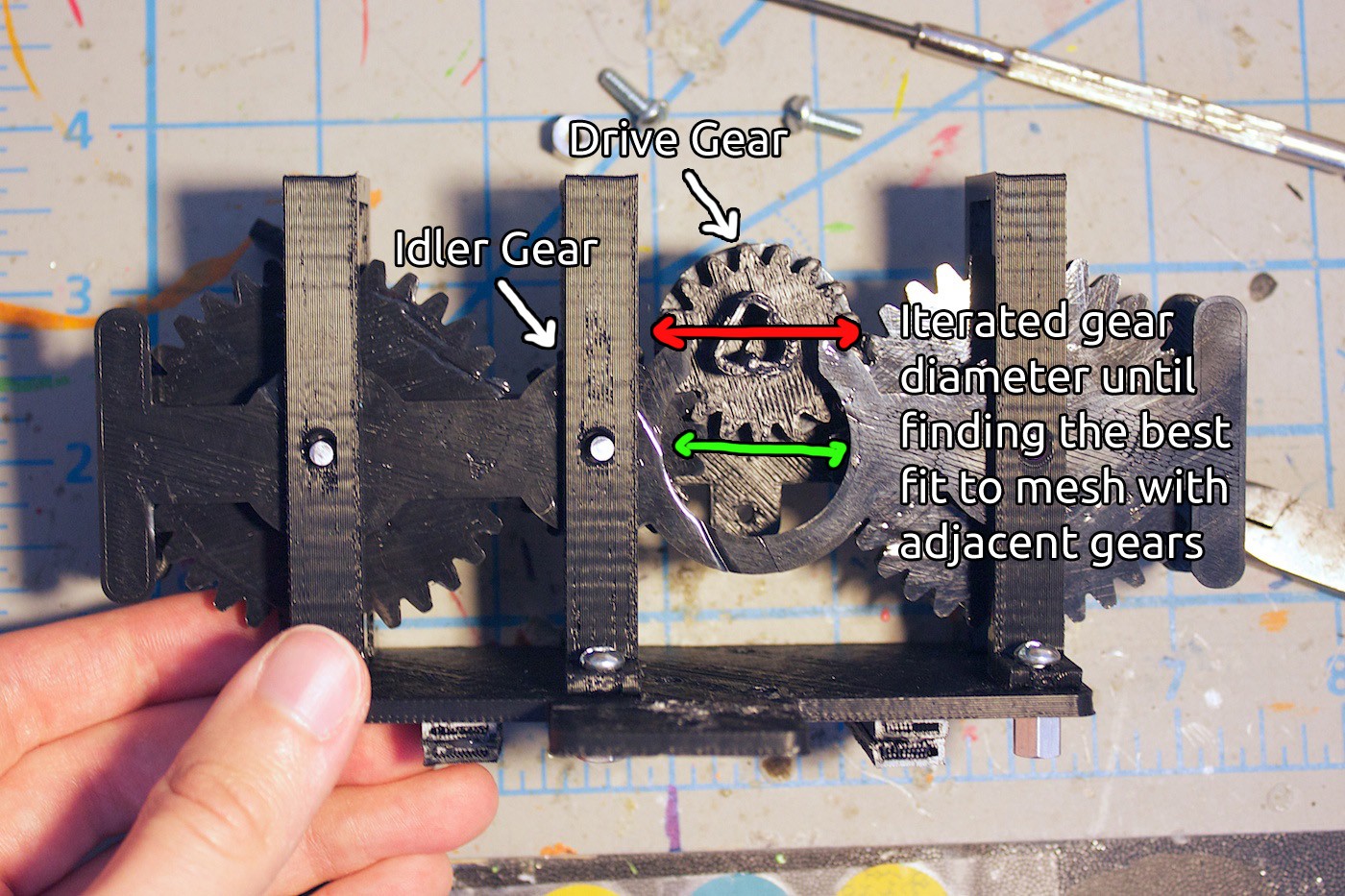
After testing the gear set, sometimes the gear teeth would slip. The drive gear would either move the pinion gear, or move the idler gear, but rarely both at the same time.
This was our next problem to solve.
![]()
The gears were generated using this feature called ‘Design Accelerator’ in Inventor. It is very handy, and produces nice gears that perform well even when 3D printed. We increased the diameter of the drive and idler gear (they are both the same size), iterated on this, and eventually found the goldilocks size.
The drive and idler gears now mesh perfectly with their adjacent gears!
After testing this out for a little while, we noticed something bizarre with locking in the gear set to the two racks. Sometimes the bar attaching the two racks would need to be longer or shorter than previous, even though nothing much has changed.
We went back and forth on this problem for quite a bit. The gear set would move up and down the rack quite well, but then sometimes it would just stop. It was weird.
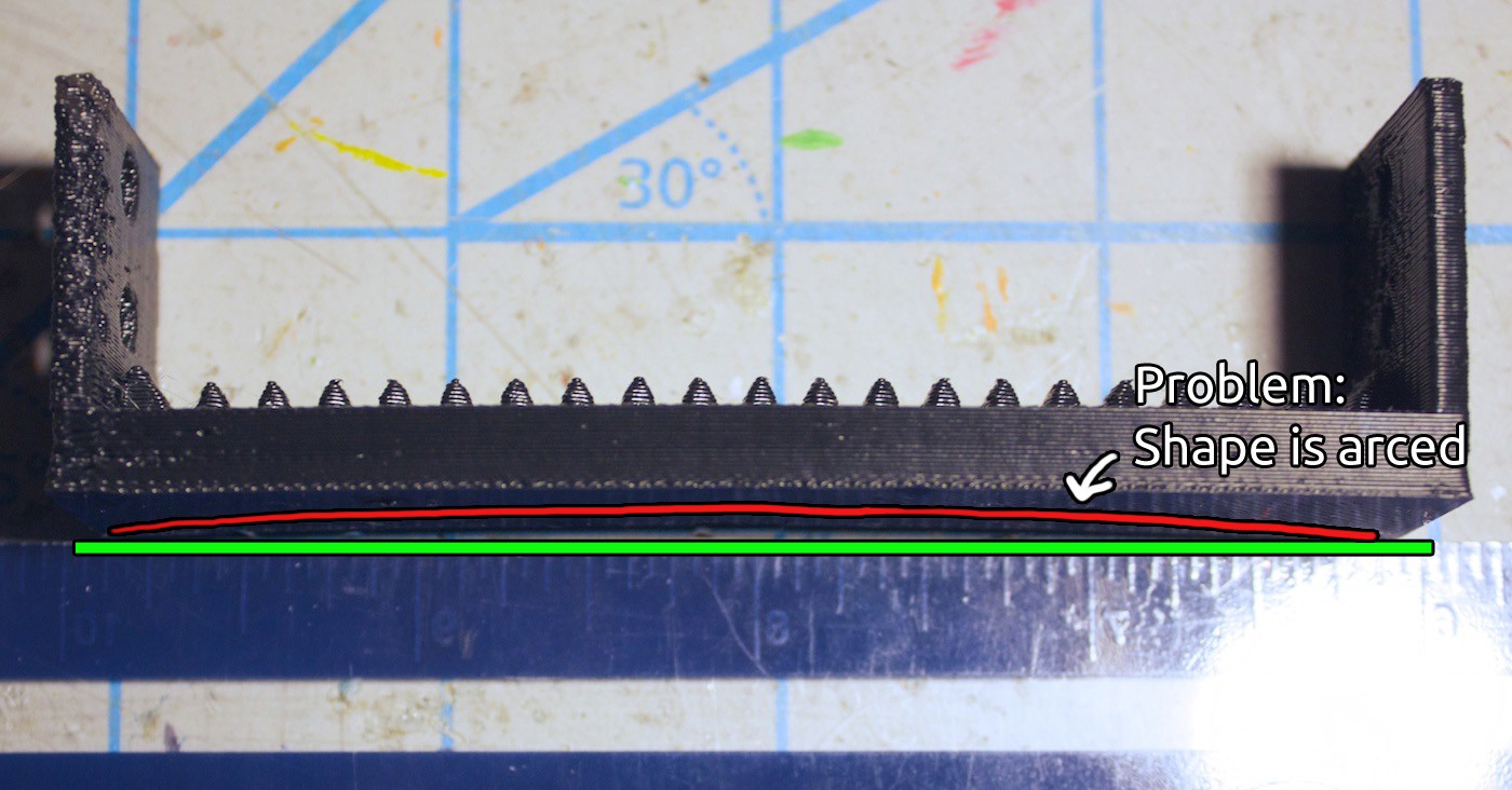
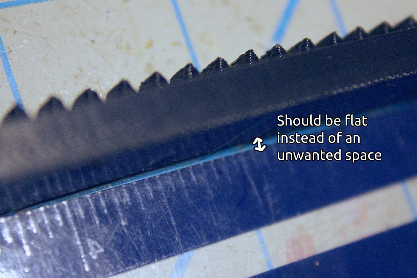
Finally we noticed something- the rack pieces are arced!
![]()
Here is a closer view of this:
![]()
The rack piece should be flat. It would mess up if it wasn’t flat, because there would be varying degrees of pressure placed onto the gear set, which may cause it to not work. This is different than warped 3D prints, where warping is due to a malformed first layer or an issue with the build platform, or inconsistent heating during a print.
The reason why it is arcing, from what we have come to understand of 3D printing, is because the ABS is trying to stay attached to each of the printed layers. Each ‘strand’ on the long sides of the piece pulls upwards.
There is no room for the strands to be relieved. If there were spaces in the first few bottom layers, it would prevent this from happening.
So this is where we are at now. We have to work on a way to make this piece not arced. But we don’t want to design it to be flimsy, where it could bend when in use. Which would sort of be like the same problem, but reversed. We’re going to start out with the spaces idea and see where this leads.
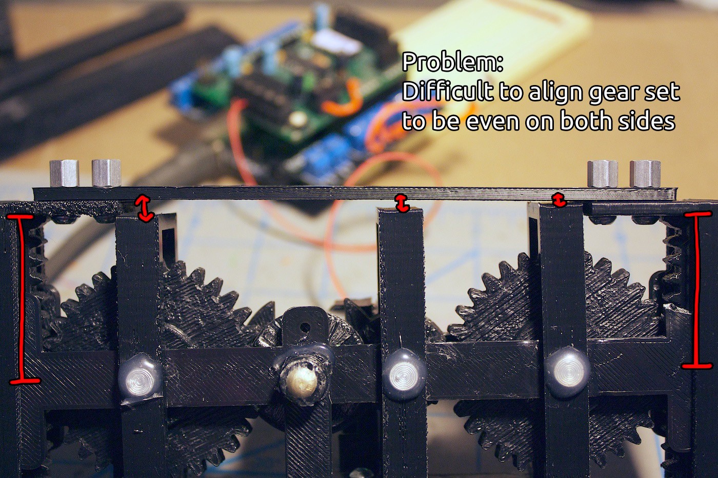
Here is another problem to be fixed in the upcoming revisions. It is difficult to align the gear set when sandwiching it between the two racks. Need to come up with a way to solve this.
![]()
Moving forward, there is the encoder disk and LDR to play with. This will require some tinkering to get it to work properly and semi-reliably. It will be interesting to see how well the feedback system will be able to work to hold the position of the gear set along the racks.
![]()
We’re not sure if the motor will be strong enough to press down with the knife to cut an object. The sensory feedback from the encoder can a little help with this. We could command the motor to be constantly driven, giving more force than if it were released, and thus applying pressure to the knife. Until we receive feedback that the position of the gear set has moved. We will have to see how it works out during tinkering and go from there. :)
Lessons Learned
It seems a lot of building things that move has to do with being able to restrict the movement in the directions other than the one it is moving in. This was an interesting lesson to learn when trying to keep the gears parallel to each other.
We also learnt that even if a shape is flat in the design, you have to pay attention to the fabrication method and materials used. Now that we have realised this, we can update the design to compensate for the arcing of the ABS!
Thanks for the comments on the discussion page. ;)
Also worthy of note, Cyberlane wrote a thought-provoking question about knifes, cutting angles, and rotary blades. We’re planning a larger post on this topic, so stay tuned!
If you have any questions or ideas that maybe we haven’t thought of, don’t hesitate to leave a comment! It might be helpful to us in the long run.
Until next time, making gears spin and learning new things!
-
Sketches
06/11/2014 at 05:08 • 1 commentBeginning the AFSR project was kind of confusing. It was difficult to figure out where to start. There’s many moving components in this robot. So I sketched some of the sub-assemblies onto paper. Sometimes for visibility, I skewed dimensions of the sketch to be longer.
Here is a timelapse video of the drawings being drawn.
Read more for details and ideas about the sketches!
Sketch 1
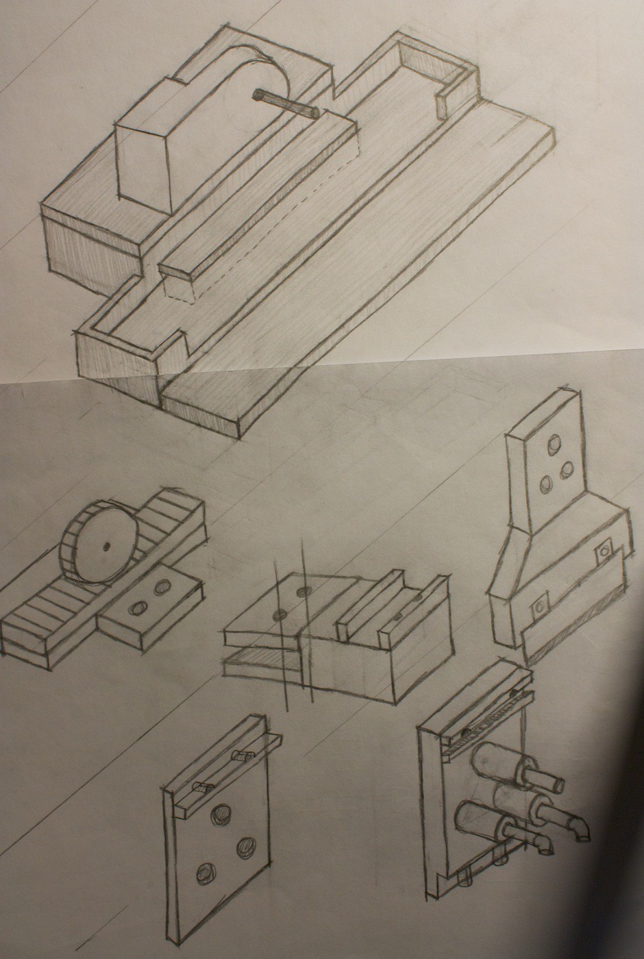
![]()
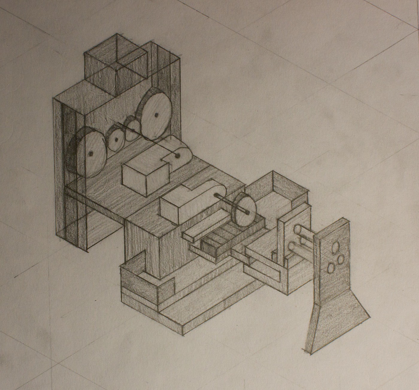
This sketch shows the Y-axis Slicer at the top, and the End Effector Attachment near the bottom of the page.
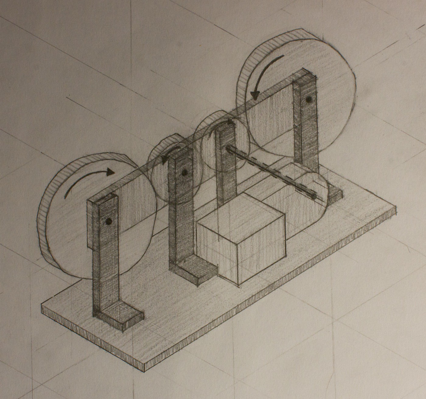
The idea with the y-axis slicer is that it will be a rack and pinion mechanism, to slide the end effector attachment back and forth. There is a tray with the y-axis slicer to make sure that the entire mechanism won’t slide out. Depending on the motor speed, the gear ratio may need to be reduced.
The end effector attachment clamps on to the main tool using three cylinders. The thought here is that the two cylinders on the bottom will be able to take most of the force from the cutting, and the cylinder on the top will be used to align the assembly together. There opposing side will ‘clip in’, and hold the tool inside of this ‘case’.
By using cylinders, I’m hoping it will be easier for easy disassembly/reassembly than it would be with a longer rectangle shape. Once you have one of the cylinders through, then find the 2nd, and then the 3rd will automatically follow. As opposed to having to angle everything and push the piece in at the same time, if it were a rectangle.
We’ll see how this all works out after testing it. It’s the first idea.
Sketch 2
![]()
This is the ‘carriage’ of the Z-axis carriage. The thought here was that the gear set will be able to be between the two sides of the racks, and move up and down.
Except that this wouldn’t actually work, because the frame would not be able to fit around the gear set.
Sketch 3
![]()
Solving the fitting around the gear set problem would be easy by having the racks attach to bars, which would attach to a clip to hold it all together. Also there are now spaces for pieces of the gear set to slide along, to keep the entire assembly aligned.
Sketch 4
![]()
This is what the gear set would look like. Something very simple, with a small drive gear, the same size for an idler gear, and two large gears to serve as pinions.
Sketch 5
![]()
One of the aspects of this whole project I’m struggling with figuring out is how all of the sub-assemblies will attach together, and where. This is an example of the Z-Axis Carriage attaching to the Y-Axis Slicer.
This probably won’t be the best way to attach it, because it will flex upwards, and snap at the attachment point.
More brainstorming will have to be done on this. Thinking it will be easier to visualise this when the sub-assemblies are actually printed out.
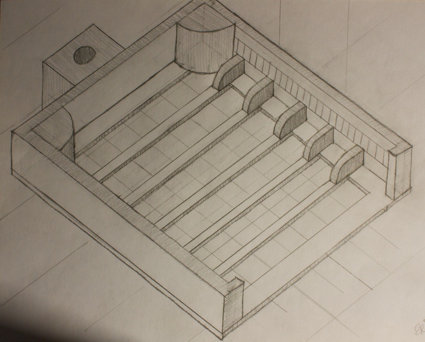
Sketch 6
![]()
This is the front view of the entire robot. It also shows the remote panel mounted on the side of the robot. Notice how there are very few buttons, and a giant e-stop button. The hope is that it will be straight forward for people to use.
The X-axis spans across the entire robot, plus some space to the left to account for the size of the gantry.
The food is resting on a removable cutting board, which is on top of a cutting table. Under the cutting table are some force sensors, then the bottom table. The force sensors will be used to weigh the food. It will also be interesting to see if they can be used as feedback for cutting, to see if the piece of food has been completely sliced to the bottom.
Sketch 7
![]()
A cropped version of the above sketch, focussing on the chassis for clarity.
The first fail of the project goes to a drawing I made where there were 3 gears in the gear set, and this gear set was attached to a rack, using the outer two gears as pinions. This doesn’t work because the two pinions wouldn’t be moving the rack in the same direction. Yeah. #FAIL. Luckily caught the error before wasting too much time on it.
My focus right now is on the Z-axis Carriage. Created a model a few days ago and printed out the first trial pieces today. Now have to analyse them and iterate on the design to make it work.
Automatic Food Slicer Robot
Accessibility robot, bringing confidence and safety to those who have difficulties cutting food
 EK
EK