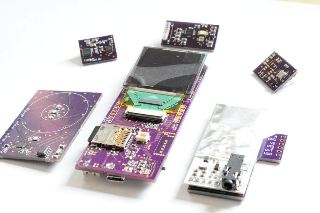
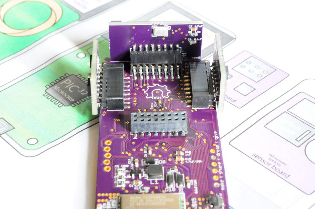
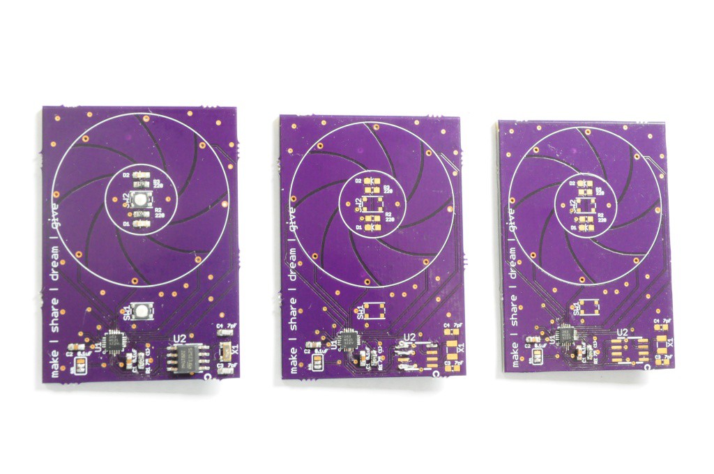
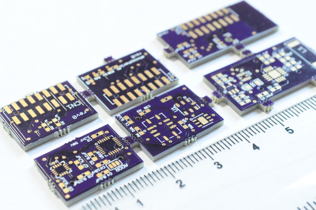
-
And then there were three...
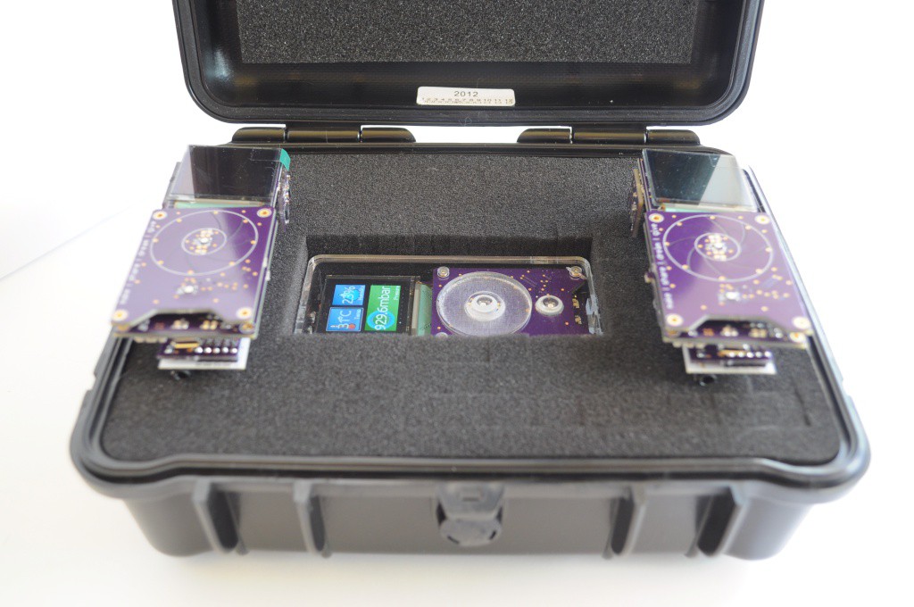
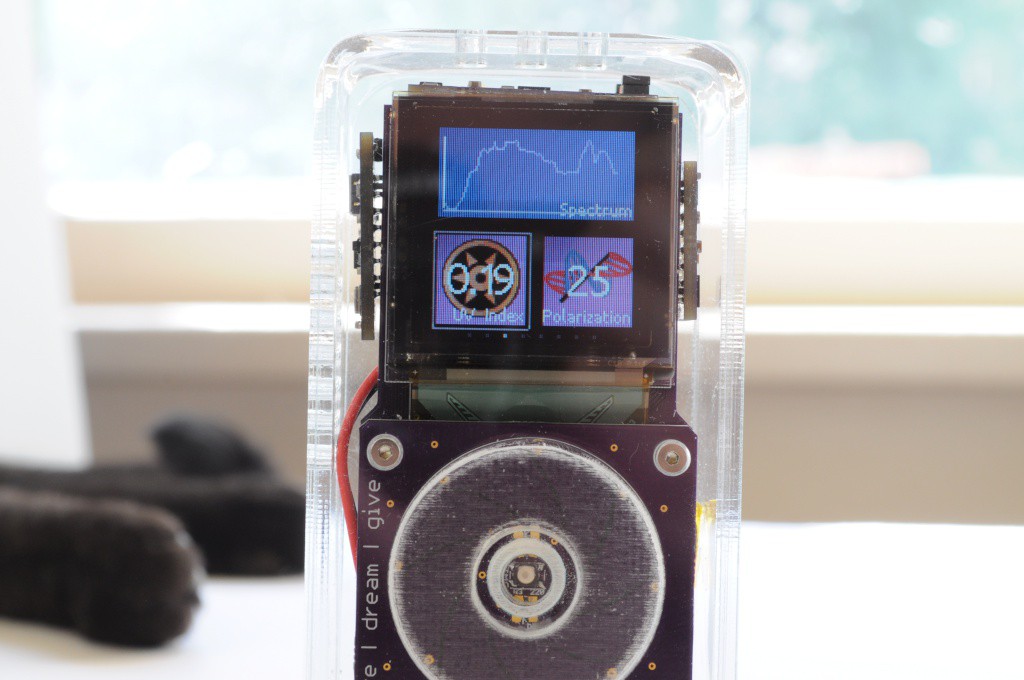
03/10/2015 at 17:47 • 3 commentsA quick update -- I was packing up the Arducorder to ship off to @Mike Szczys for the Hackaday Prize booth at SXSW, and thought I'd snap a picture of it fitting snugly in it's new instrument case and shipping enclosure. I hope the folks at SXSW enjoy it, and all the other finalist projects from 2014!
![]()
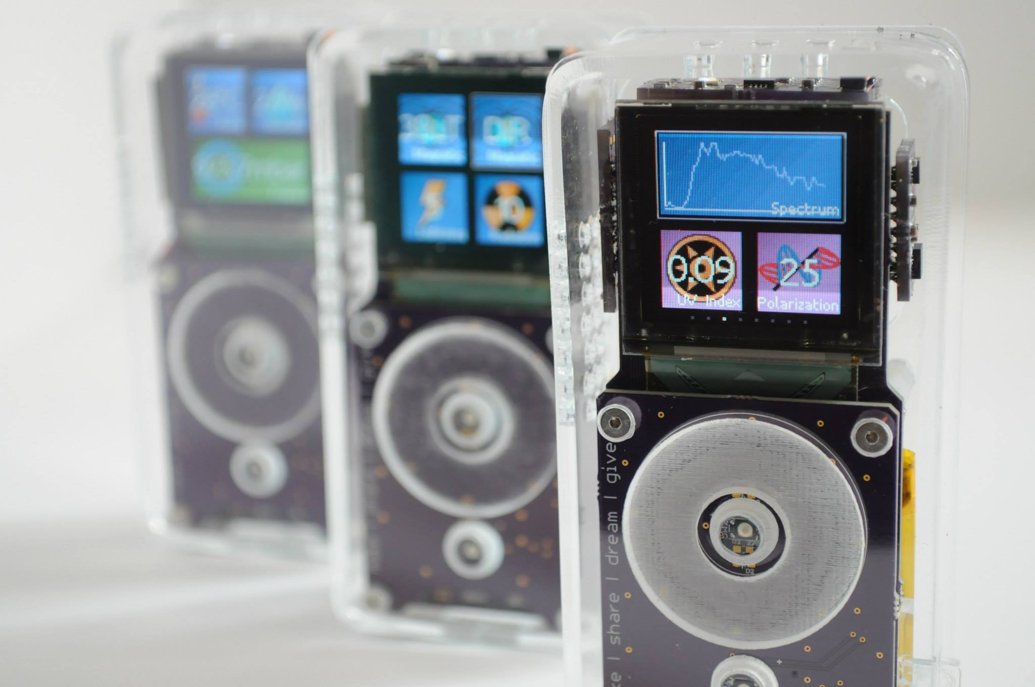
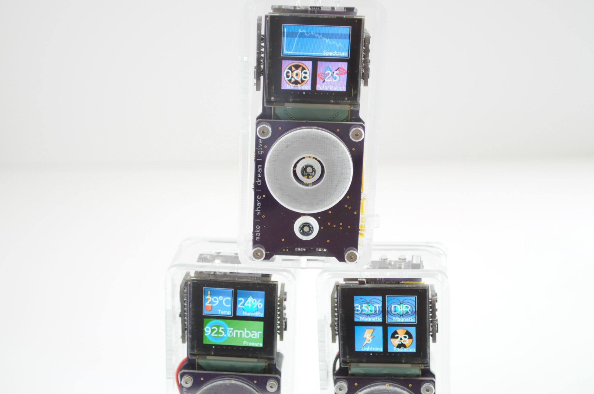
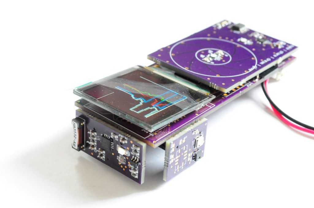
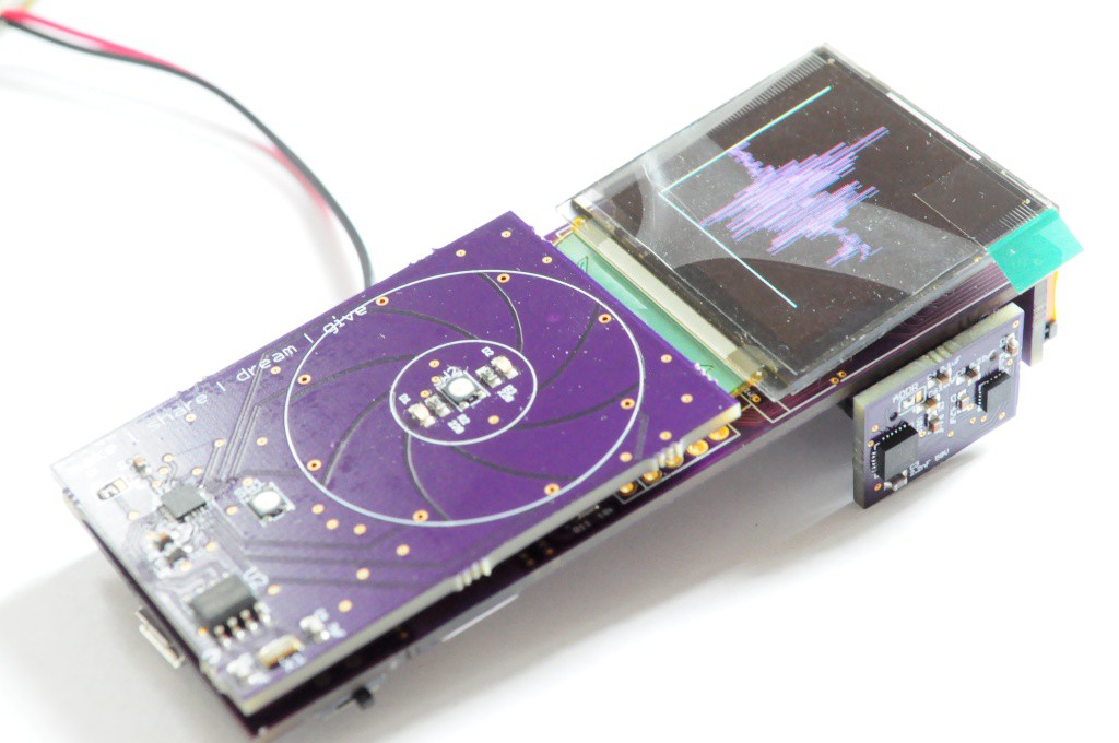
The other exciting news is that I've /finally/ completed two more Arducorders, with the exception of their enclosures. The original enclosure had some specially machined standoffs inside, and so I'm hoping to put together a slightly modified enclosure with entirely off-the-shelf hardware later this week. Each Arducorder has 7 double-sided PCBs totalling about 200 components, and takes me the equivalent of four full days to assemble (this work is really intended for pick-and-place machines), so it's really incredible to see them when they're finished.
One of these -- the second one made -- is going to my very excited father, who helped teach me to make, build, solder, and learn from a very young age. I've been tinkering with developing a science tricorder-like device with everything on my sensor wishlist for nearly ten years, and have always said that the second one off the line would be very warmly given to him, as thanks for helping show me the joy of being a scientist, and being a wonderful and supportive dad.
Developing a complete, modern open source science tricorder-like device has been on my bucket list for a long while, and the Hackaday prize helped me reformulate the project into something tractable enough that it could be designed and built in five months, capable enough that I could include exciting new sensors like micro-spectrometers and high energy particle detectors, and elegant enough that it could make both myself (and, a panel of judges) happy to carry it around in one's pocket. I'm sure like all the other finalists, the last three months were incredibly intense, and between the lab at school and my Arducorder building I was putting in 12 to 16 hour days, every day. I was desperately scared of being knocked out of the competition after the semifinals -- not because I wanted to win, but because I wanted to finish, I knew it would take until the end of October to get there, and I had been pushing myself so hard for so long that I'd likely have collapsed and slept for a week were I knocked out, and lost some steam. I'm extremely grateful that things worked out the way they did, and that the Arducorder is a real, working device that sits on my desk, and has a complete set of plans for folks to build their own, improve upon the design, or use aspects of it for their own projects.
With the Hackaday Prize 2015 launched today, I'm very excited to see what folks will come up with to help change the world, and make it a better place. I'd like to thank the folks at SupplyFrame for putting this incredible competition together, and helping me make the Arducorder possible.
Update: More Pictures
![]()
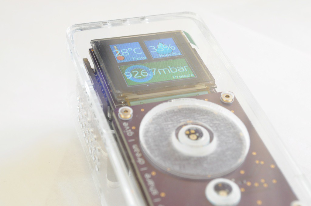
The first three Arducorders that I've built are complete, and they look beautiful. I'd vastly underestimated the time that it would take me to assemble them -- each unit likely has somewhere around 80 hours in it, which is more than double what I was expecting. For those building their own, don't forget that the driver for the touch wheel has a noise threshold that may need to be calibrated for each unit.
![]()
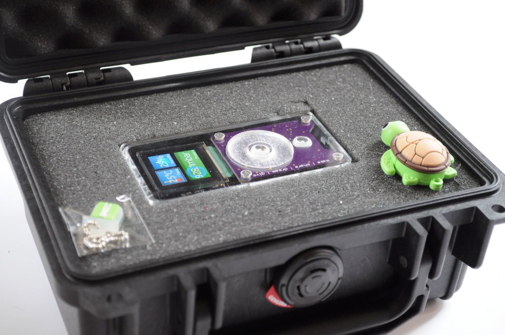
They fit perfectly into a Pelican 1120 case, which are very compact travel cases with plenty of room for extras, like USB drives with firmware.
![]()
Thanks for reading!
-
Spectrometer Group Buy, and see the Arducorder at CES!
01/07/2015 at 06:37 • 0 commentsJust a quick update, and my apologies for taking a while to update -- I think I speak for all the Hackaday prize finalists when I say that the push to finish was absolutely exhausting! In the mean time I've been very busy catching up on writing two papers in the lab, visiting with family over the holidays, taking care of a sick kitty, and trying to find a few hours of rest.
![]()
Arducorder at CES
The good folks at Hamamatsu have borrowed the Arducorder this week to help demonstrate their beautiful C12666MA micro-spectrometer in action. If you happen to be at CES, be sure to drop by the Hamamatsu booth to check it out!
![]()
Micro-spectrometer Group Buy
The C12666MA micro-spectrometer is a beautiful instrument, but it's also not the easiest to get ahold of in small quantities. The folks over at Group Buy (who helped get the FLIR Lepton thermal imager out into the community) have a group buy for the micro-spectrometer at the fantastic price of $180, or about $50 off the regular single-quantity pricing. This is a really fantastic deal, and if you've been assembling your own Arducorder (or would like to experiment with the C12666MA micro-spectrometer), it's a great opportunity. As of writing there are only 4 days left to get in on this group by, so you'll likely want to act quickly.
![]()
Power Switch!
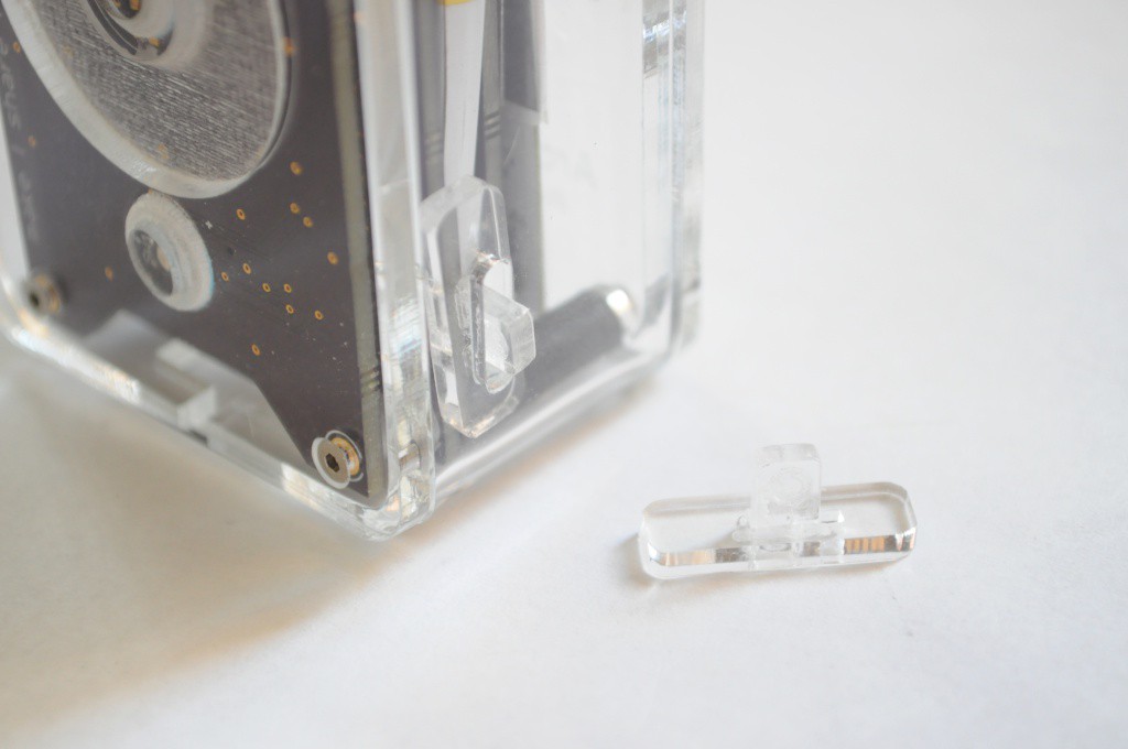
Every designer has aspects of a project that they do well, and places where they could use a little improvement. Power circuits are where I usually need improvement, and I tend to overengineer them for efficiency so much that occasionally they're simply too complex to work on the first revision. The Arducorder has a very good and high-efficiency buck/boost power circuit, but the case design was missing an important element -- the acrylic slider that covers the power switch, and lets you easily turn the unit on! Free yourself from the bounds of having to carry around a tiny screwdriver or paperclip, and cut out this power switch slider :).
Just a quick update -- thanks for reading!
-
Project Video, and Plotly data!
10/28/2014 at 06:33 • 1 commentThe project video is up! It's been a very busy few weeks building the final revision boards, putting together an enclosure, and adding the final features to the software. I'm absolutely thrilled at the results, and I hope it helps you make little discoveries -- everywhere.
Connectivity with Plotly
The Arucorder Mini now interfaces with Plotly -- a website that's like social media for data, that I've absolutely fallen in love with. After hours of rearchitecting the Plotly Arduino library (with Chris from Plotly's help -- thanks Chris!), there is now a beautiful, fast library for Arduino that supports multiple streams, blazing fast transfers, and normal plotting functions. Please use it, and send me links to your amazing streams.
The Arducorder now supports one touch uploading to Plotly -- you can literally pull the device out of your pocket, and in 20 seconds have sensor data streaming or spectra shared with friends on the other side of the planet. It's really incredible, and I'm pleased with the results.
![]()
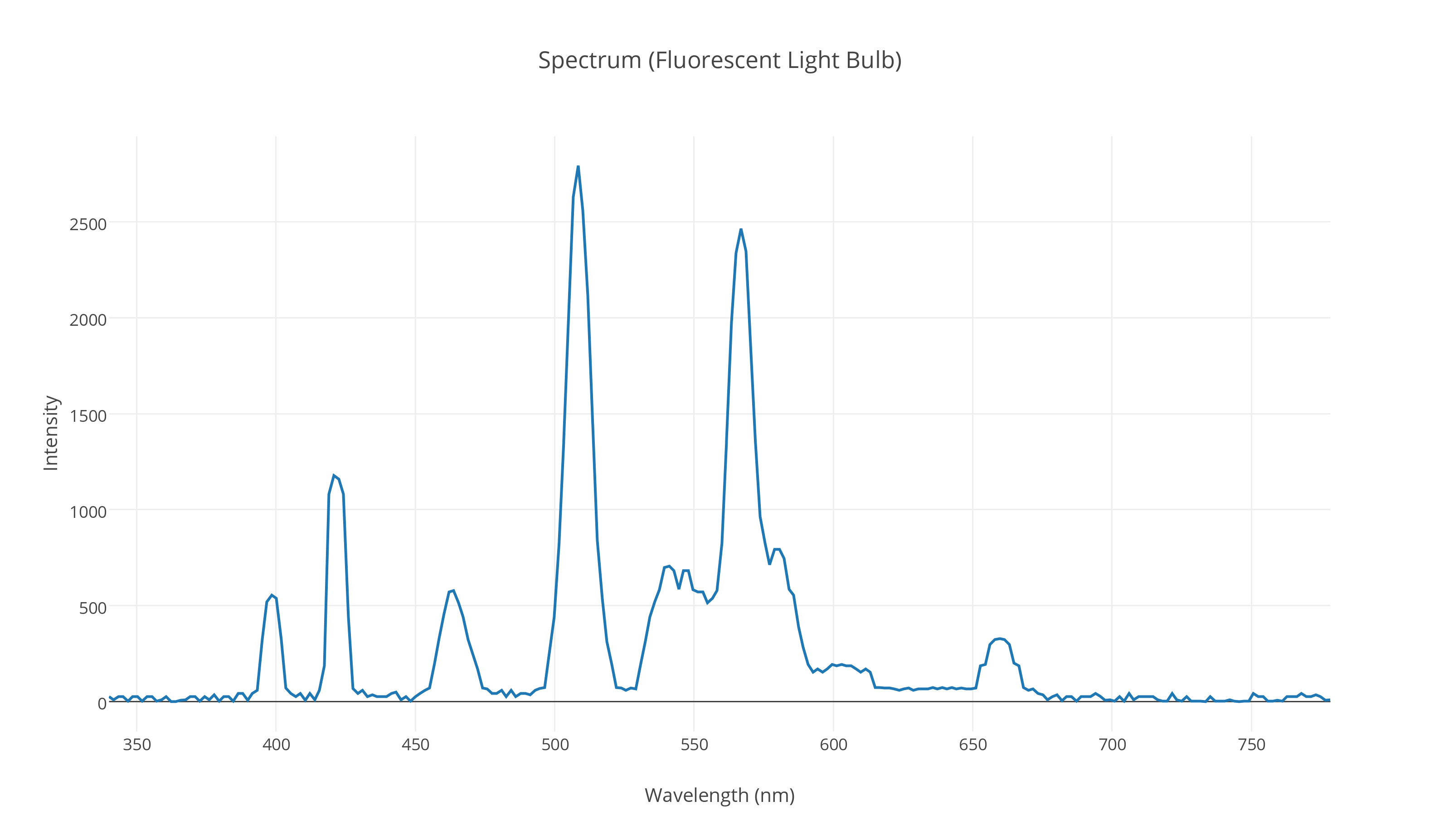
The data used in the video is all available on the Arducorder Mini Plotly profile. Here are direct links to some of the data, including:
- Solar Spectrum, Incandescent Spectrum (both black bodies), Flourescent Spectrum (above). I think you can even resolve the deviations from black-body radiation in the solar spectrum to see the O2 lines and Aerosol contributions near the peak!
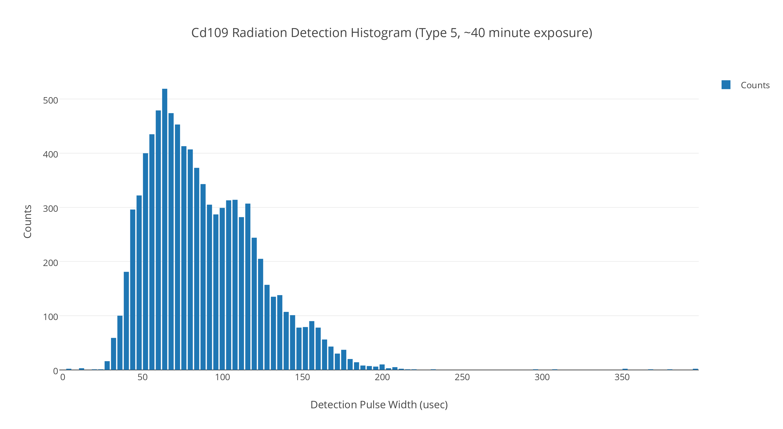
- Pulse width histograms for the Barium-133 and Cadmium-109 radioisotope sources
In addition, I will try to keep some of the data from the live streams used in the video active, including the atmospheric stream, magnetic field stream, radiation stream, and inertial measurement unit stream.
![]()
Build Instructions and Acrylic Case
I've tried to put together a case that would help draw people in, while being functional and easy to construct and disassemble for tinkering. Thanks to Connor and David from Xerocraft for helping me figure out the settings for precision laser engraving, and machining the delrin standoffs!
![]()
Thanks to everyone for their kind words and helpful comments over the project! While designing and building the device is very rewarding, I feel like the real fun is just starting -- actually using the device, and having a reconfigurable scientific multitool to explore the world around us.
I hope you enjoy the video, and thanks for reading!
-
Hardware Revisions -- Preparing for Release
10/11/2014 at 05:47 • 6 commentsAfter a marathon programming session, the different modules of the software came together wonderfully for the prototype video nearly two weeks ago -- it's been very exciting to see the Arducorder Mini hardware coupled with an attractive and intuitive user interface:
Hardware Errata
I tend to think of first prototypes as a sketch -- in hardware -- that's as close to the final project as time and experience afford, but with the knowledge that for a sufficiently complex project there will always be an errata, or list of items that need to be modified or corrected in the next revision. The idea here is to make our mistakes cheaply so that everything has the best possible chance of working the first time -- and to ensure that we have enough wiggle room to tinker with any critical bits that don't work the first time, so we can quickly narrow down any design changes for the next revision.
With PCB turn times taking about two weeks, my recent focus has been revising the few issues that popped up when validating the hardware, and sending these new boards off to be made. It's my hope that if everything validates fine, that these boards will be the first official release candidate for the Arducorder Mini.
![]()
Motherboard
I confess that when I designed most of the first revision boards, I failed to include mount points on the motherboard and capacitive touch board that would allow the whole thing to be placed in an enclosure! This was a bit of an issue, since the motherboard is only 2-layers, and so densely populated that I had to increase the size a small amount (4mm in both width and height) to accommodate four M2 mounting holes. If I was willing to increase the PCB specifications to 4-layers the board would have been significantly less dense and made mounting much easier, but I'd like to keep the specifications as low as possible so that the boards can be made inexpensively, and the open source community can easily modify the designs with the free version of Eagle CAD. I remember years ago reading that when Stephen Hawking was writing A Brief History of Time, his publisher told him that his readership would be halved for every equation he placed in the book. I feel the same about open hardware -- for every barrier I place on people easily modifying the hardware -- expensive software, 4 layer boards, etc -- that it will reduce the reach by at least an order of magnitude. So I'm trying to keep it simple and accessible.
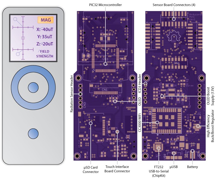
Other than mechanical considerations -- the four mounting points, and switching to a connector for the capacitive touch board itself with mounting holes -- there are a few minor schematic changes for the motherboard:
- Added I2C pullup resistors on motherboard
- Fixed VCC/GND pin swap on two sets of the PIC32 pins
- The OLED 13V booster VIN is now sourced from the 3.3V regulator instead of the battery. When sourced from the battery and the booster was disabled, the OLED 13V line would be equal to VBAT, causing a few pixels to stay on, and draining the battery a bit.
These are largely minor changes, and the technical challenge is largely in rerouting big chunks of an existing board for the modifications.
![]()
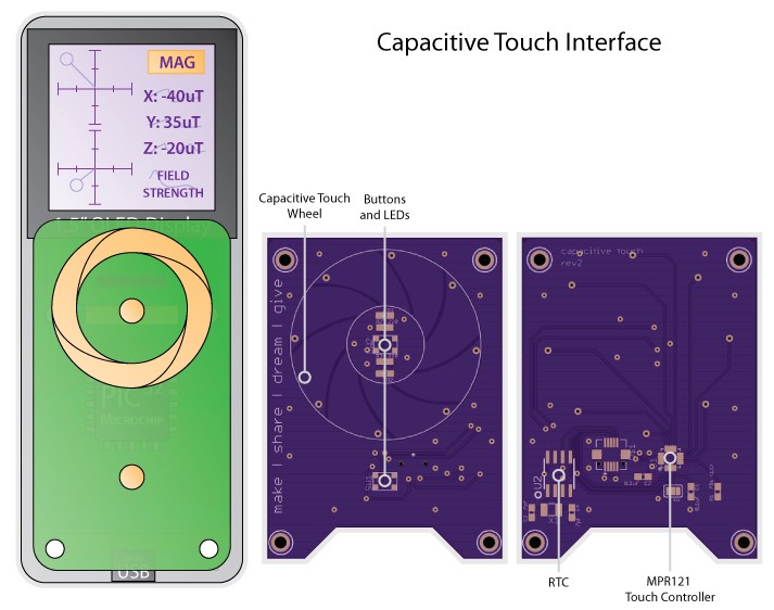
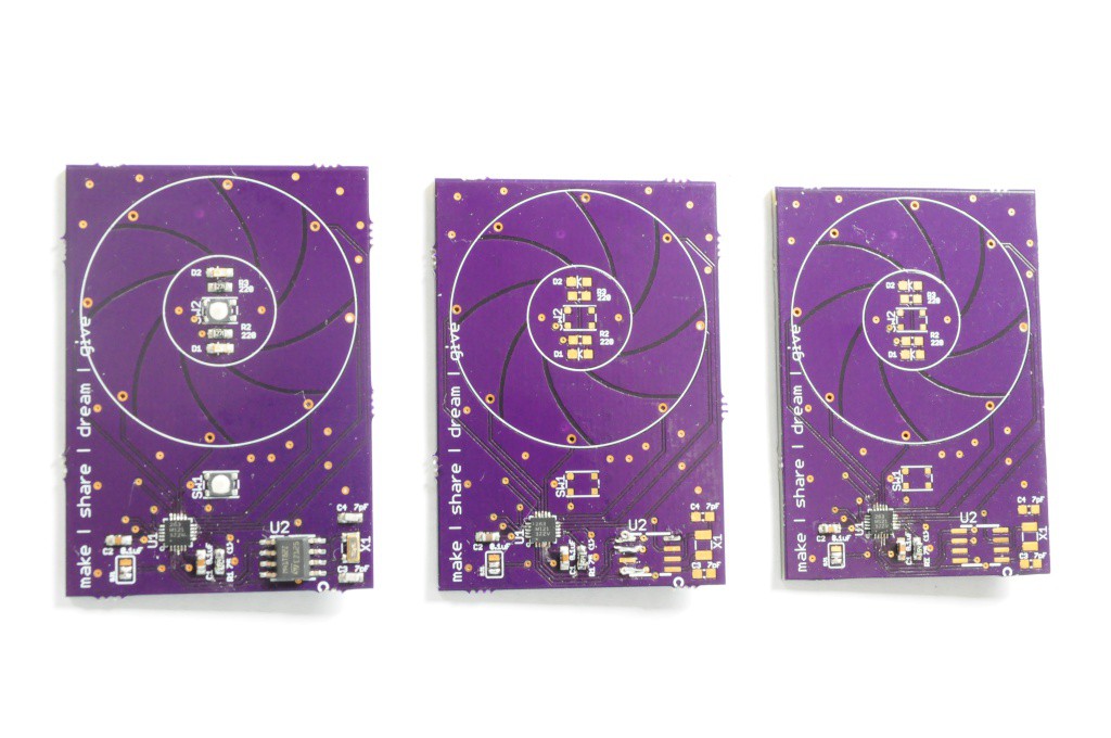
The capacitive touch wheel board also has largely mechanical modifications to allow it to securely mate with the motherboard, and to mount in a case. The parts have all been moved to the underside of the board (except for the two pushbuttons), leaving a flat surface for some acrylic to mate with for the touch wheel. I'm hoping to have the opportunity to camp out infront of the laser cutter at Xerocraft one evening in the next week or so to design an attractive case with the hardware in hand.
To help the indicator LEDs for battery charging and programming to shine through to the front face of the enclosure, I've added the small notch along the length of the bottom of the capacitive touch board. Inventables has some back-surface laser-engravable acrylic that looks very interesting, so I've ordered a few pieces and I'm excited to see what some icons for the OK/BACK buttons and indicator LEDs will look like.
![]()
Finally, the radiation sensor backpack board also includes some minor revisions. In my rush to finish the first version of this board I forgot to include the pull-up resistors for the comparators, which I think is causing them to bounce a little on transitions (high energy particle detections). This didn't appear to be a huge issue when I was using the demo code for the Radiation Watch Type 5, but the interrupt-driven Chipkit driver that I put together for this sensor appears to be much more sensitive.
I've read that this sensor is technically capable of doing limited spectroscopy, so I've also included code in the driver that supports automatically generating pulse-width histograms that may end up being correlated with x-ray/gamma spectra -- it'll be very interesting to see these with the Cadmium 109 check source when the radiation signal has a known precision pull-up!
![]()
On a personal note, this very hungry and adorable little fellow found himself on my porch a few weeks ago, and I've nursed him back to health. Hopefully I can find him a forever home in the next week or two -- he's so young that he's still not mastered putting one foot infront of the other, and sometimes that foot lands on an Arducorder Mini!
Thanks for reading, and stay tuned!
-
Tile-based User Interface, and Spectrometer Board!
09/17/2014 at 06:31 • 1 commentUser Interface Design
Visualization and user interface design is a hobby that I really enjoy, and I've been lucky enough to have friends and colleagues who are usability and visualization folks that I've been able to periodically soak information up from. The open source science tricorders present a really interesting UI problem -- where most mobile devices have at most a few different sensing modalities, here we have 12 different physical sensors, each of which measures between 1 and 3 different things! What's more, while some of these measurements are single values (like temperature, say 24C), others are vector values (like the three separate 3-axis vectors coming from the MPU9150 -- one vector for acceleration, rotation, and magnetic field strength, giving nine values total, from a single sensor). In the extreme case, the spectrometer returns a vector of 256 values. That's a lot of data! I'm really not aware of any other device that comes close to having so many different kinds of sensing data pouring into it constantly, and while this is very exciting, it's also challenging -- we want folks to intuitively browse and navigate through that data very quickly.
I've spent the past few weeks researching design concepts for user interfaces by browsing popular design websites, and talking to some friends, and I think I've settled on a very intuitive, attractive, and useful interface design. I'll confess that I've been working harder, not smarter about this in recent years -- I'd try and design very complicated things that looked like how other people had done mobile devices and visualization (like android phones), which is a fantastic amount of work for a single human being. Starting this Arducorder mini project almost 4 months ago, and keeping it attractive and capable but tractable has finally helped me work smarter about this, and figure out a lightweight, usable and intuitive interface concept.
![]()
I like the idea of live tiles. When done well, it reminds me of Danny Hillis's idea (30 years ago) about maximizing the amount of computing silicon active on a processor at any one time, but attractively applied to data visualization. Instead of having icons that just take up space and give you a name, here you have tiles that display a live updating value. This is powerful from a usability perspective -- instead of having to enter each application to obtain this information (which can consume a lot of time), the most important information is available at a glance from many applications. While this has largely been applied to communication (e.g. messaging), web (weather/news), and I'm sure sensing applications, here we're going to construct an interface made almost entirely of sensor data.
The really interesting aspect (if you're a data abstraction nerd, like me) is that if we consider only this special case -- visualizing sensor data through tiles -- then we can formulate the software engineering aspect of this very elegantly. If each tile has a sensor data buffer behind it, then we can browse it's most recent data on the top of the tile, then activate the tile to display additional (historical) data and different visualizations. If we abstract the sensor data buffer into a few different types, like continuous streaming data (from something like a temperature sensor or an accelerometer) and discretely sampled data (from something like a lightning sensor, that only activates when an event occurs), then we can get rid of the idea of an application. The design concept becomes browsing sensor data buffers first through a high-level tile interface, and then activating an individual buffer and using a suite of generic visualization tools to better explore it.
![]()
Interface Implementation
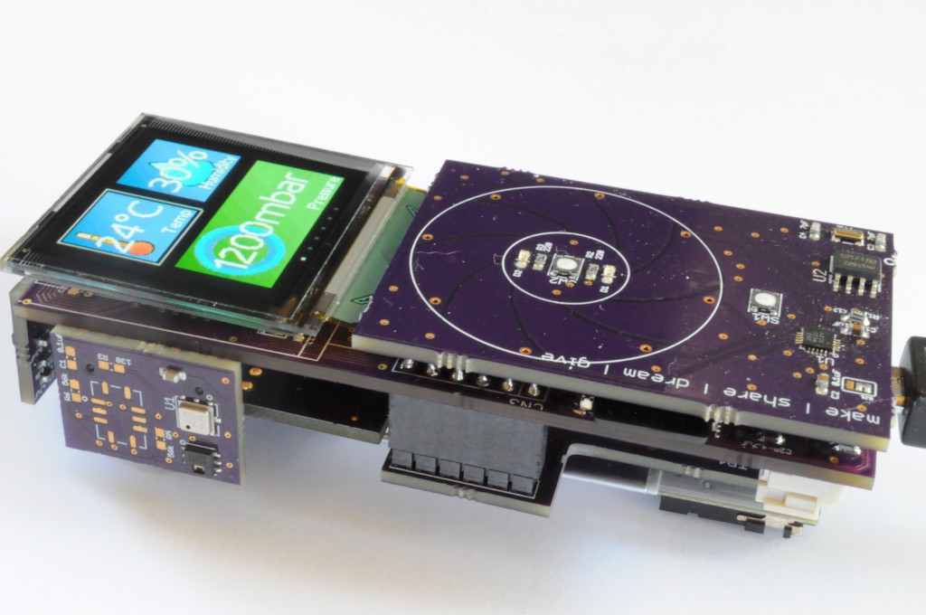
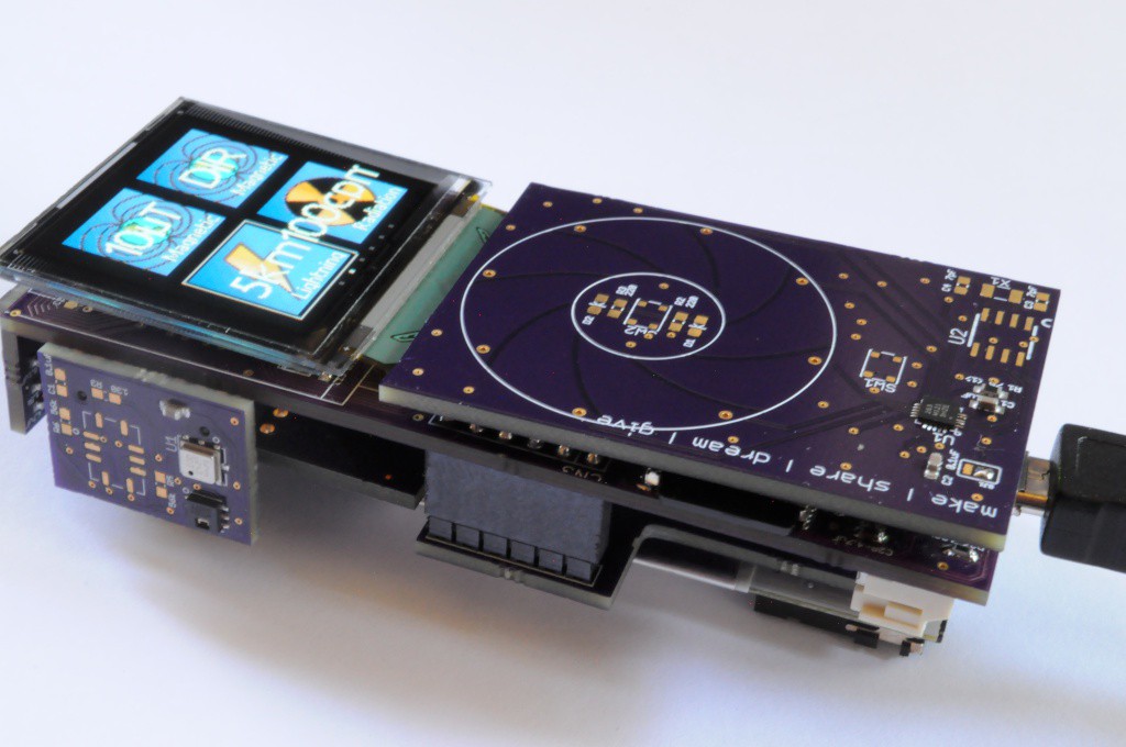
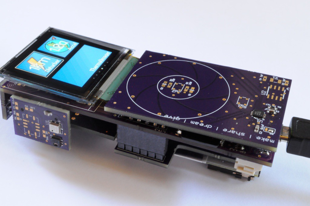
All of the software engineering aside, what the user sees is very attractive -- tiles with live data that they can browse through very quickly with the capacitive touch wheel. The tiles themselves are rectangles with a linear gradient, a bitmap (using the posterizing tool I posted in the last update), a small right-justified name on the bottom, and center-justified data in larger text. The bitmaps are all designed to have simple easily-recognizable shapes and gradient colour palettes to make them sharp and attractive.
![]()
The tile engine itself is still incomplete -- I need to link the tile data structures to the sensor data buffers elegantly, so right now the tile data is just static placeholder text. There are also two tile types where I'd like to replace the bitmap symbol with actual data. The first is for the 16x4 thermal imager, where I'd like it to show actual 2D image data, and the second is for the spectrometer, where I'd like it to show a small 1D spectrum.
![]()
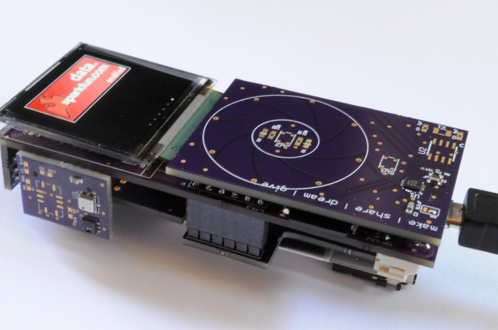
Finally, in addition to sensor data tiles, I'd also like to include utility tiles that allow someone to change a few important setup parameters. Connectivity is a huge theme for a device like the Arducorder Mini, and this could take you in many directions. I've decided the first of those directions will be to interface with the data.sparkfun.com cloud data storage service, which was recently put together by the folks at Sparkfun for exactly this purpose. I'm okay at scientific and embedded programming, but not terribly experienced with web programming, so I think putting together the software to interface with this service (on the Arducorder Mini side) will be a great working example for amazing web programmers with a tinkering spirit in the open source community to do wonderful things.
![]()
Spectrometer Board
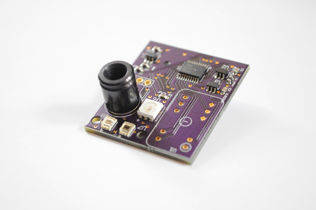
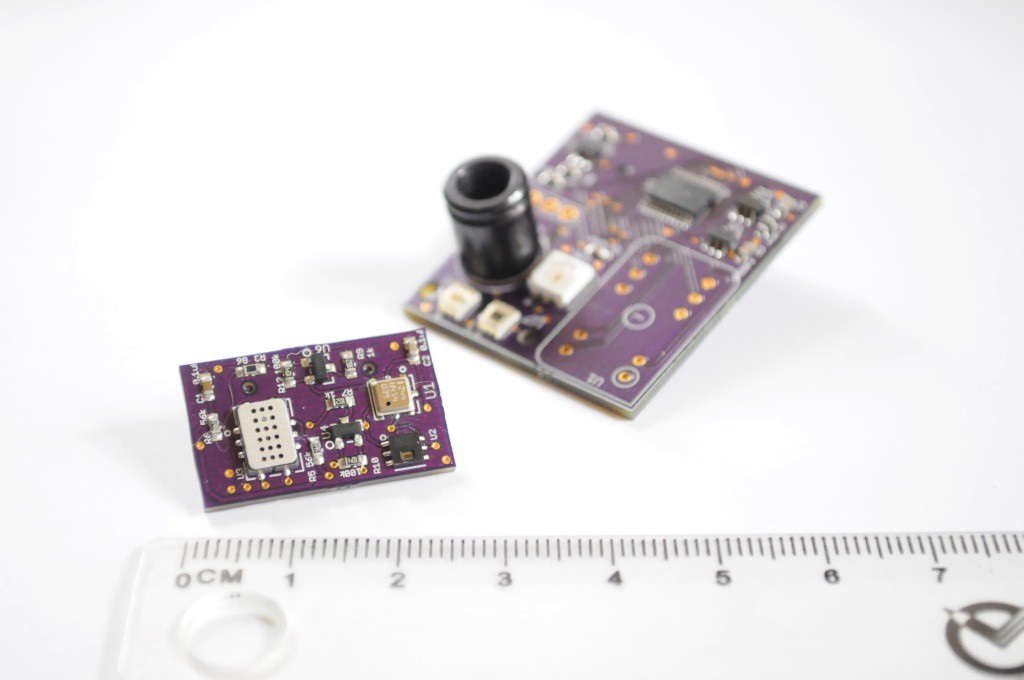
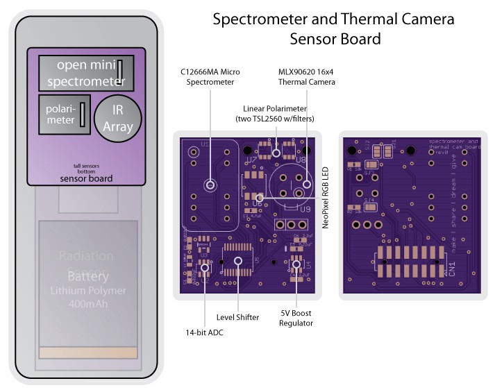
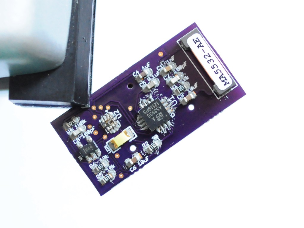
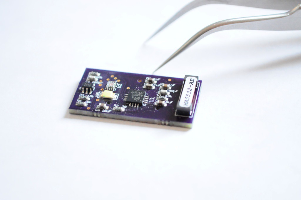
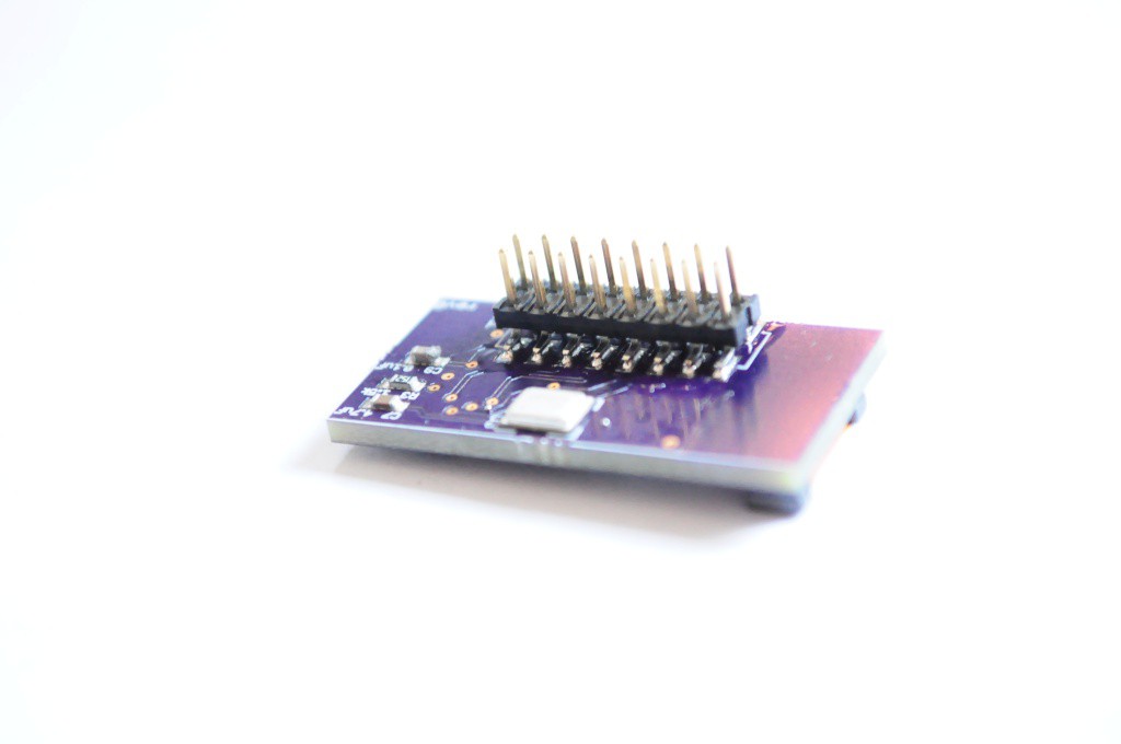
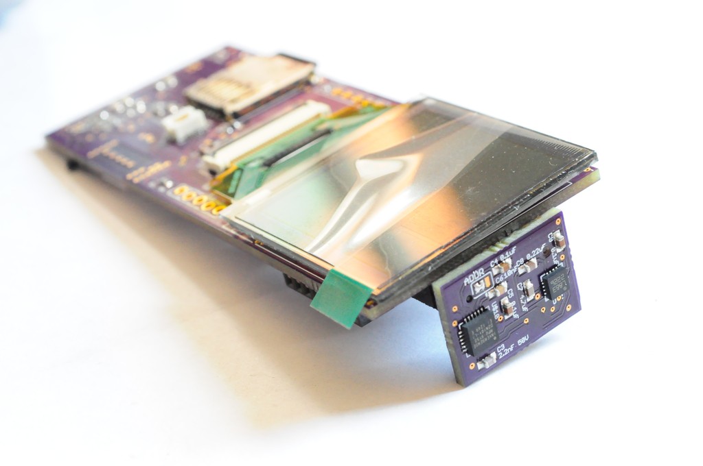
On the hardware side, the spectrometer/thermal camera boards arrived, and I put one together this week. The brand new Hamamatsu micro spectrometer is a longer lead time part, but should arrive sometime late next week (likely a little short of time to get it working in time for the semifinal video). This board has a lot on it, and the rest is ready to test! The 16x4 MLX90620 low resolution thermal imager, an RGB light source for initially experimenting with the spectrometer (and a header for optionally adding in a different light source overtop later), and two light sensors that narrow-band filters can be placed overtop of (here, to construct a polarization sensor). There's also supporting circuitry for the mini spectrometer, including a 5V boost circuit, a 14-bit ADC, as well as an opamp and power filter to keep both electrical and thermal noise at a minimum.
![]()
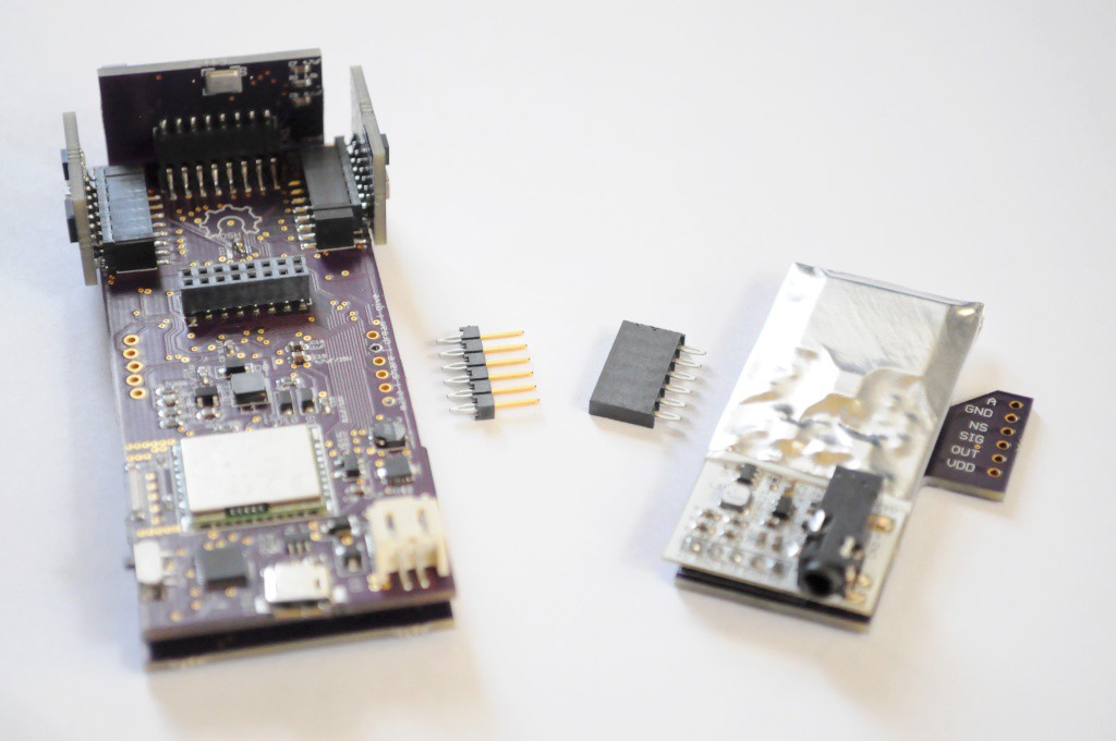
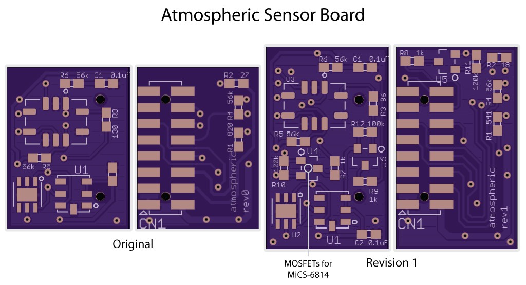
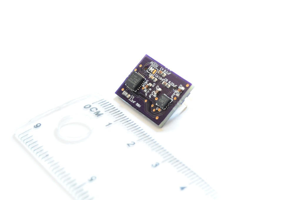
Finally, the second revision of the atmospheric sensor board also arrived, which now includes MOSFETs to handle the ~30ma current draw for each of the heaters used by the MICS-6814 triple gas sensor. This means that it shouldn't blow up the I/O pins of the PIC32 when I try to interface with it. This board also includes the HTU21D humidity and BMP180 barometric pressure sensors. It's difficult to describe how very tiny these boards are, so I included a ruler in this picture -- the atmospheric board is literally the size of the tip of my finger, where the "huge" spectrometer board is more tip-of-the-thumb sized. It's really incredible!
It's really rewarding to see all of this take shape, and to see the user interface evolve, and all of the puzzle pieces starting to come together. There have also been a few late nights over the weekend, in no small part due to a hungry baby kitten showing up on my doorstep, and spending most of the last few evenings nursing it back to health. The other night when I went to record the video for this post, I had thought the Arducorder Mini was suddenly and mysteriously nonworking, and it took an hour to realize that it was because the battery was dead. Turns out I'm smart like that. Glad to see all those years of grad school counted for something... :)
Thanks for reading, and stay tuned!
-
Spectrometer Board Design, and Beginning User Interface
09/04/2014 at 02:41 • 0 commentsA quick update with lots of progress designing the spectrometer (and thermal camera) board, attaching the radiation sensor board, and beginning to work on the low-level routines for the user interface!
![]()
Fast and Efficient Bitmap Rendering
Now that much of the hardware is in good shape (or being fabbed), I've been working on the low-level software and APIs that would support building an intuitive and attractive user interface.
A bit of background -- from my hobby of indie game development in undergrad and participating in the Ludum Dare 48-hour game competitions (a really fun experience!), I've picked up that in a desktop system (and some embedded systems), a graphical user interface is often functionally implemented as a large collection of bitmaps stacked atop each other with transparent layers. This has the benefit of being able to make large changes to the user interface through editing configuration files that describe which bitmap corresponds to which background or widget or font (instead of recompiling code), and also allows the user interface artist to easily use whatever tools they're most comfortable illustrating in to rapidly iterate without having to use middleware, or (even worse) be constrained to building an interface entirely out of low-level graphics primitives like squares, ellipses, and triangles.
This is the approach that I'd initially planned on using, but I'd discovered about a month ago when running a display verification test that the ChipKit SD card library has a read speed of around 100k/sec, which puts the time to load and display a bitmap on the order of about one second -- far too slow for an interface. There are faster libraries like sdfat, but these required more than a solid evening of porting, and at some point you have to put these on the wishlist, accept the constraints, and exploit the benefits of your existing system while architecting it in such a way that you could drop more advanced functionality in later with a minimum of effort.
![]()
Posterizer Tool
While loading bitmaps from an SD card is currently slow, the PIC32MX processor that the Chipkit Max32 uses does have 512k of flash memory that (in addition to code) can store bitmaps that can be loaded very quickly. A full screen (128x128) 16-bit (2bpp) bitmap takes 32k of memory, so we can't fit very many in memory, but if we manage our resources and store things efficiently, we should have plenty of space for backgrounds and widgets and icons in ~128k or so.
One way of compressing bitmaps is to reduce the colour depth -- if we can reduce an image from 16-bit colour (64k colours) to 8-bit (256 colours) or 4-bit colour (16 colours), then we can store the image in half to a quarter of the space. The trick is selecting a smaller colour palette so that the final "posterized" image still looks very good.
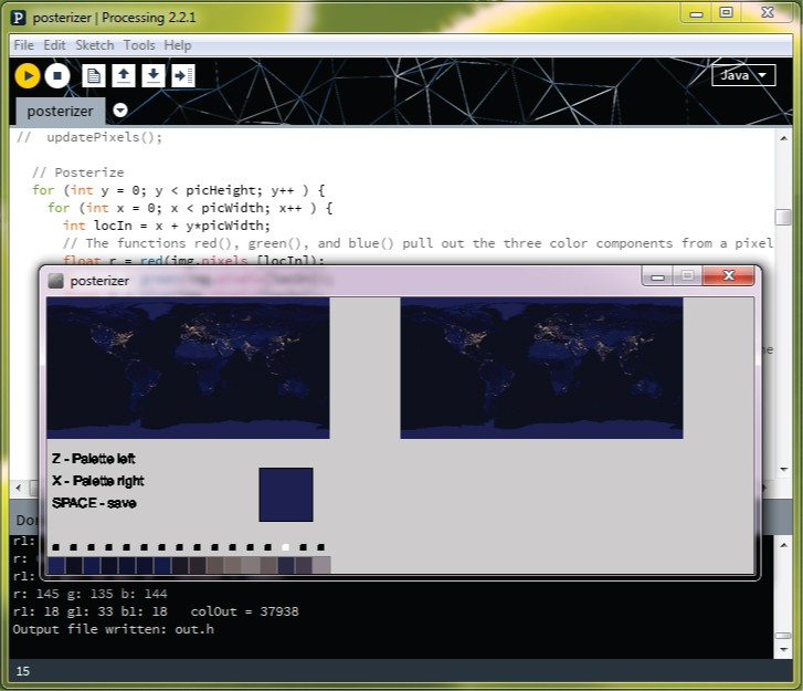
There are automated algorithms to do this, but they often give non-ideal results, and I want this thing to look /good/. I've been looking at user interface concept art the last few days to get ideas, and I'd had the idea of having a main menu that showcases a space theme by having a scrolling background under an icon-based main menu with multiple pages of icons, similar to Android. I grabbed a copy of NASA's amazing public "earth at night" photograph, downsampled it to 256x128, and used manual posterizing tool I quickly put together in Processing to reduce the colour depth to 4-bit, and store the image as a static array in flash. Despite being 256x128, the image only uses 16k of flash, and the manual conversion (above) is so good compared to an automated algorithm that I would never have known it was poserized if I didn't do it myself! It also scrolls back and forth at about 50fps, which looks really impressive. While I'm still deciding the final user interface concept, it was a good test, and a useful tool to compress the graphic assets into flash so that they're quickly available.
Next on the list of graphics routines is an attractive font renderer, which I seem to be spending a lot of time on -- but it's literally the (font) face that the user experiences with every interaction, so it's important to make it a positive experience.
![]()
Spectrometer and Thermal Camera Board
I completed the design for the final sensor board that combines the spectrometer, an LED light source, a low resolution thermal imager, and several light sensors to build a tiny linear polarimeter. This board has gone through a lot of mental iterations, but I'm very happy with the final design, and for this first iteration I erred on the side of making an instrument-quality sensor module with real utility, at the expense of a BOM that's a little higher than I'd like it.
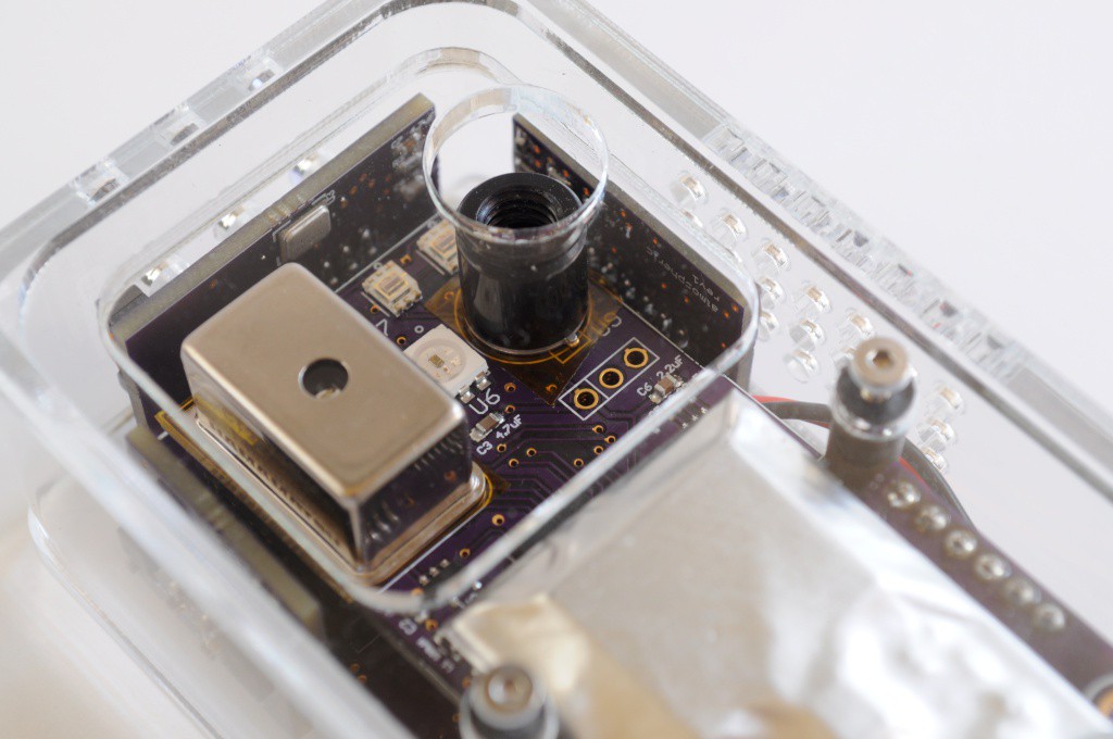
A number of folks have written to let me know that earlier this year Hamamatsu released their second-generation miniature spectrometer, the C12666MA micro-spectrometer, which is the only small off-the-shelf spectrometer part that I'm aware of. At 20x12x10mm, this is a very small part -- even smaller than my open mini spectrometer (!) -- and it's specifications are about an order of magnitude or more better in nearly every way. The trade-off is of course price, it being about an order of magnitude more expensive, too. But it looks beautiful, and I'm excited to see how it performs, as one of the first entries into the spectroscopic sensor landscape.
As an aside, one of my central design goals with the Arducorder Mini is to keep everything as accessible as possible -- whether that's using the device, modifying the code, or keeping the cost low enough that it's affordable. One of the great aspects of this design is that it's modular, and so while it's designed to be a complete multimodal instrument, different sensor boards can be left out (or added at a later date) if price is a concern. As other lower-priced sensors become available, newer, updated, lower-cost boards can also be released, which is a fantastic design decision.
![]()
Attaching the Radiation Sensor
I've made the plunge and selected the last connector for the design, which is the connector between the motherboard (top) and radiation sensor board (bottom). This connector is critical to how the whole mechanical structure comes together, so I wanted to take my time and ensure that I chose a connector that would have a good height clearance and a strong mechanical connection.
![]()
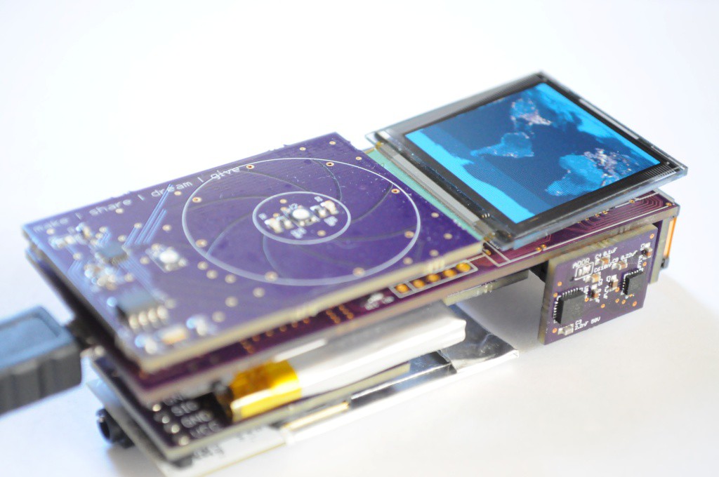
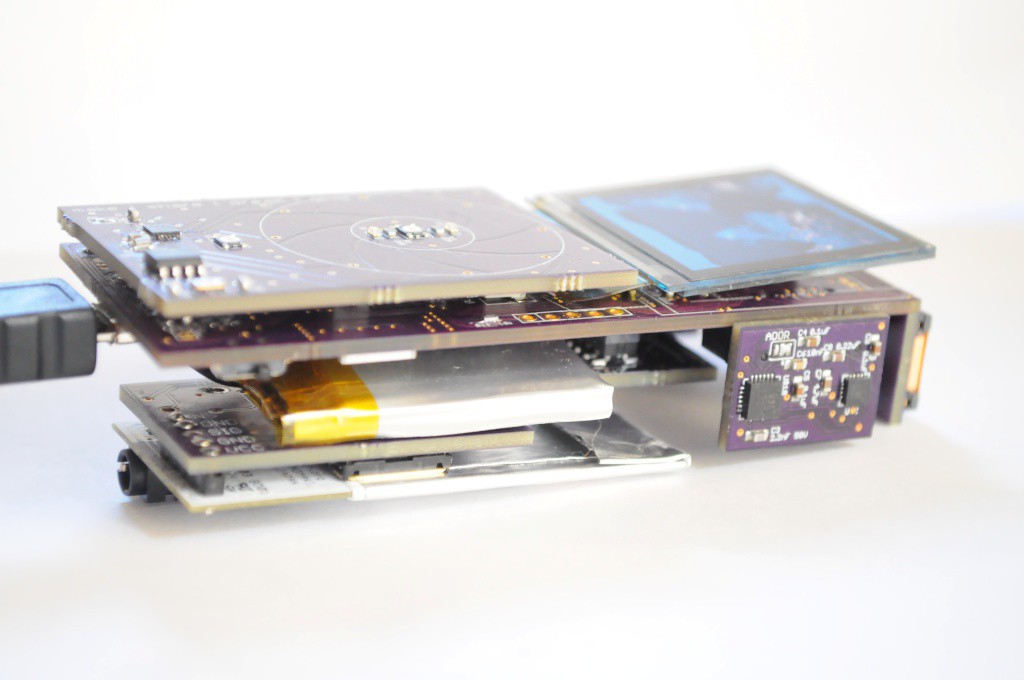
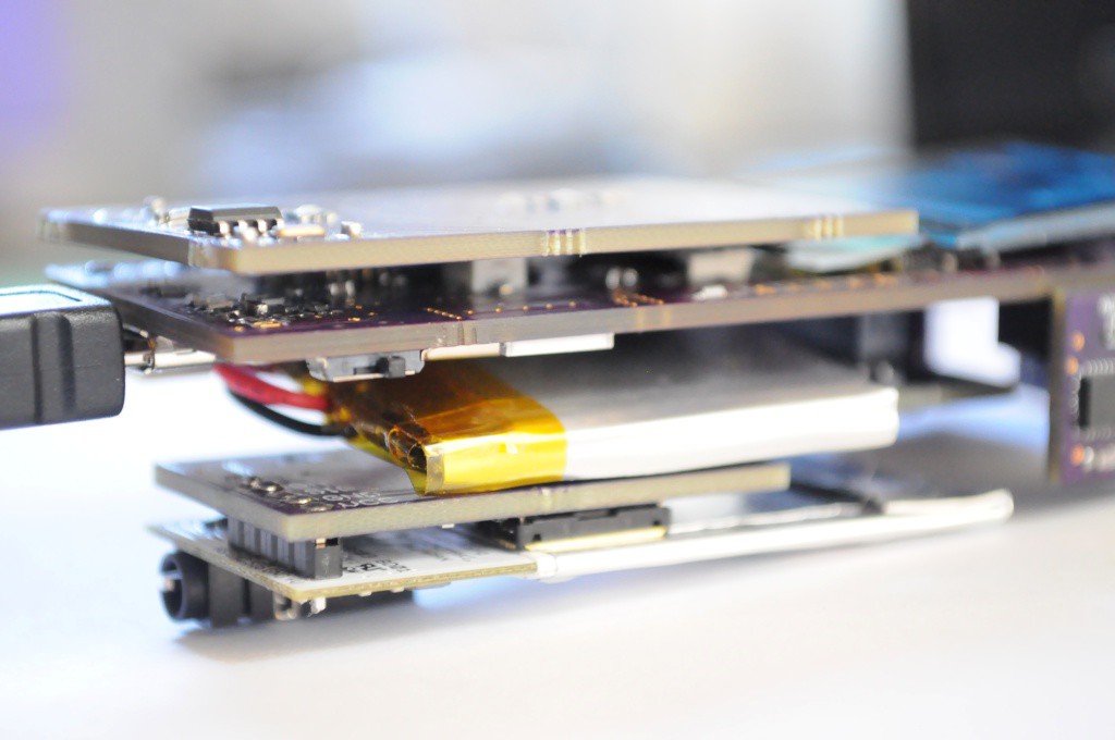
Here's the complete stack, from capacitive touch wheel (top), to motherboard, to battery, to radiation sensor backpack, to radiation sensor (bottom). In the end this connector isn't entirely perfect -- there's about 2mm of extra height that will ultimately increase the thickness of the device a bit, but this is absolutely fine for now, and we can always move to a different connector if a better alternative presents itself.
![]()
It's really rewarding to start to see the device take shape. If everything goes as planned, the entire first revision (and several second revision boards) should be here and ready to assemble in about two weeks, and several of those are the /really/ cool sensing modalities like the spectrometer and the low-resolution thermal camera, so I'm quite excited to have it all together!
![]()
Thanks for reading, and stay tuned!
-
Update: Now with 100% more WiFi!
08/27/2014 at 06:41 • 2 commentsA quick update, with some of the high-risk high-gain aspects of the project!
![]()
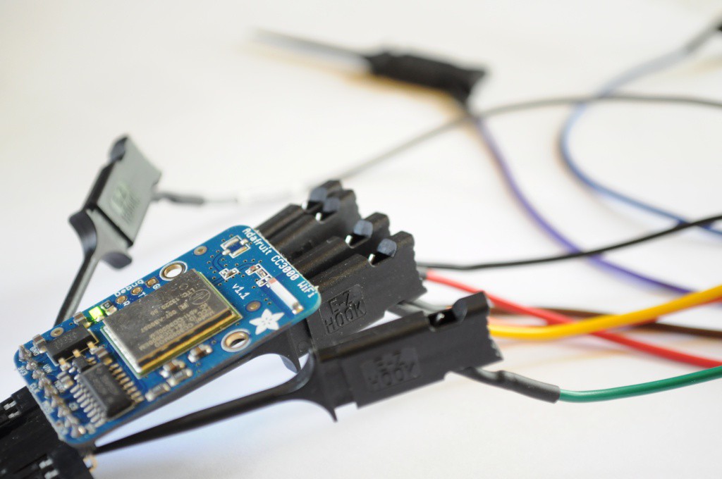
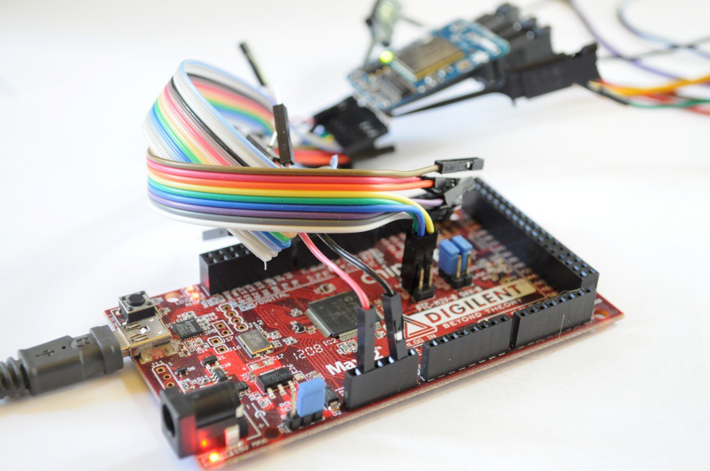
CC3000 WiFi Module and ChipKit Library Port
It's great to get out of your comfort zone and learn new skills or expand your familiarity with different aspects of design. For me, in addition to the capacitive touch wheel, I decided to include the popular CC3000 WiFi module from Texas Instruments. I think connectivity fits a lot of the use cases for a science tricorder-like device, from kids using social media to share their sensing and measurements to engage themselves and their friends, to nerdy scientists that spend their entire days in the lab (like me) who would like to push all their raw data to somewhere like data.sparkfun.com for sharing, advanced visualization, or later analysis. Personally, a neat visualization experiment I'd like to try is to sit the Arducorder Mini on my desk for an afternoon when we're expecting a storm, and visualize the storm coming in through data -- the decreasing temperature and pressure, increasing humidity, reducing distance-to-lighting, and it'd be neat to see if any x-rays from close lightning strikes are detectable and coincide with the lightning detection.
![]()
This is my first use of a WiFi module in a project, and so my concerns in terms of hardware were routing the antenna traces correctly, and being able to successfully interface with the module using an open library. There are a number of open reference designs for the CC3000 antenna circuit, and space being at a premium I ended up using the same layout as the folks who designed the open Spark Core (thanks Spark team!). In terms of open ilbraries, Adafruit released their CC3000 Library, which was recently ported to the Due, which would give me a trail of github commits to look through when porting to the ChipKit MAX32-based system that the Arducorder Mini is based upon. It all looked good, so I incorporated the CC3000 module into the Arducorder Mini motherboard.
To make a bit of a long story short, I ran into a problem similar to the issue with the capacitive touch sensor requiring the ChipKit I2C library to be updated from the Arduino 0023 libraries to the new Arduino 1.x (post-Due) libraries, to make use of the additional features that have been added in the last few years. With the capacitive touch sensor, it was fairly easy to add the repeated stop condition support from the newer Arduino 1.x I2C/Two-Wire libraries, but the Adafruit CC3000 library is based on the much larger Arduino 1.x ethernet library, so there was a good deal of effort involved -- porting the Adafruit CC3000 library from the AVR/Due to the PIC32 from the top, while simultaneously updating the ChipKit Arduino peripheral libraries from the bottom.
![]()
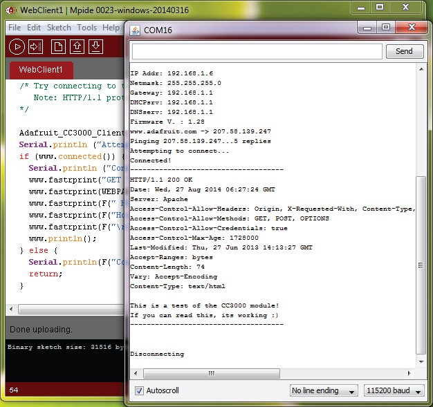
Fully updating the ChipKit libraries to Arduino 1.x would be a full-time task for someone familiar with their inner workings for a good week or two, so it's well beyond the scope of this project -- but after a solid weekend of work I was able to successfully port enough of the Arduino 1.x ethernet library (and its dependencies) to then port the Adafruit CC3000 library to the ChipKit! The picture above shows success, and the Arducorder Mini successfully fetching its first webpage and displaying it over the serial console. Great stuff!
In the end, this means that in order to compile the Arducorer Mini firmware, I'll also have to maintain an updated version of the MPIDE on the github repository. A side effect of this will be that Chipkit folks should be able to enjoy the benefit of some (partial) Arduino 1.x compatibility.
![]()
Open Mini Spectrometer
In addition to the WiFi module, the other high-risk high-gain aspect of the Arducorder Mini is creating a new version of the open mini spectrometer suitable for one of the low-profile modular sensor boards. I really needed to build (and not code) last weekend, and have been boring some of my rock-climbing buddies (who are optical physicists) with the idea of making a tiny pinhole spectrometer without any relay optics for a few weeks, so it was time to make a first prototype and see how it would work out.
![]()
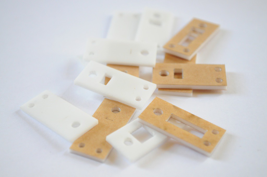
One of those rock climbing optical physicists (who is much more skilled at climbing than I am) suggested that instead of 3D printing out the spectroscope as I did originally, that the ~0.2mm kerf of the laser cutter at our local hackerspace Xerocraft might yield a reasonably thin slit while being amenable to being built in 2.5D with a sandwich of laser cut pieces, like the Open Source CT Scanner. This is a great idea, so I decided to try it out.
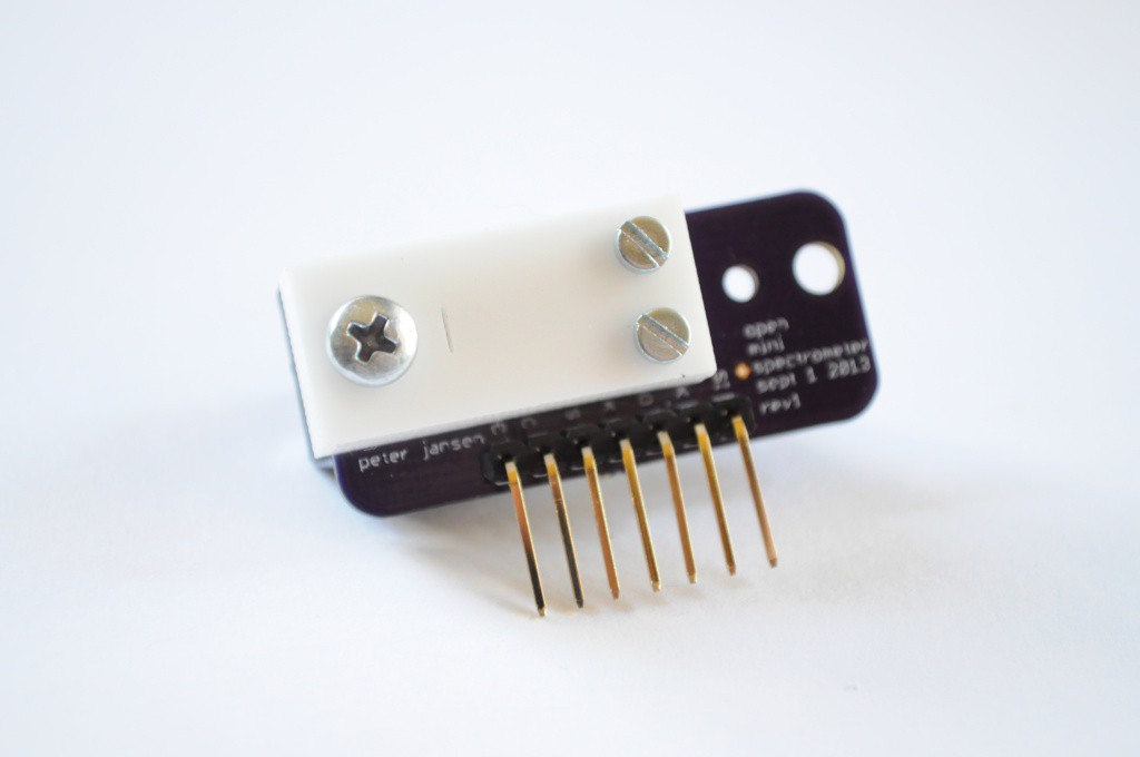
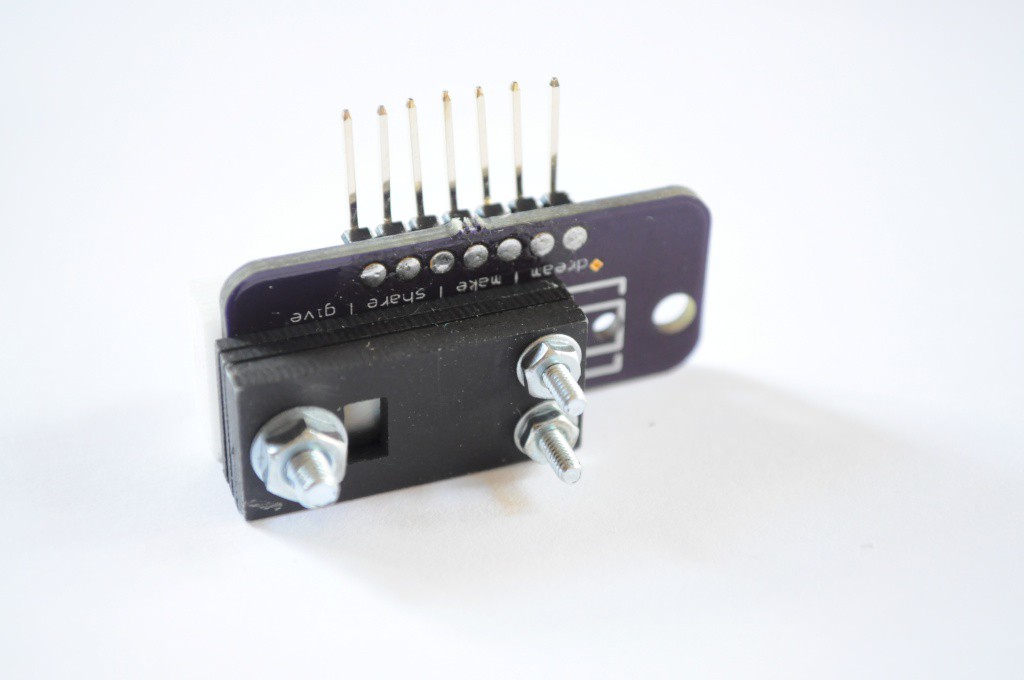
In order to make a low-profile spectrometer that doesn't stick out, the spectroscope (the optical bits of the spectrometer) actually has to live on both sides of the circuit board. There should be about 6mm of clearance on the back of the board (between the sensor board and the motherboard), and about 8mm of clearance on top of the board. I drew a few sketches, and cut out a first test spectroscope that would fit on one the open mini spectrometer boards (for testing) out of some thin 1.5mm plastic that I found in the material bin (pictured above).
![]()
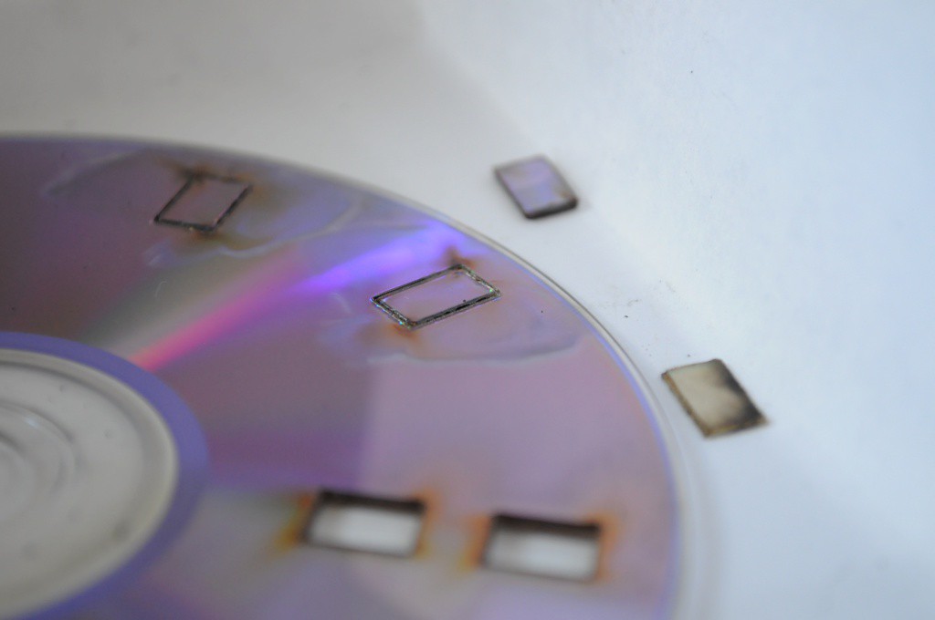
While I used an inexpensive 1000 line/mm transmission diffraction grating sheet for the first open mini spectrometer, I've seen a lot of folks (like PublicLabs.org) get impressive results with much larger spectroscopes built from DVDs used as 1350 line/mm reflection diffraction gratings. I decided to try laser-cutting a section of DVD to precisely fit into the laser-cut acrylic spectroscope sandwich, but it turns out this isn't a fantastic idea -- the tiny DVD-piece gratings end up being covered in residue from the process, or delaminating, or seemingly changing their properties entirely. I tried cutting out about half a dozen, and taking the best to make a solid attempt.
![]()
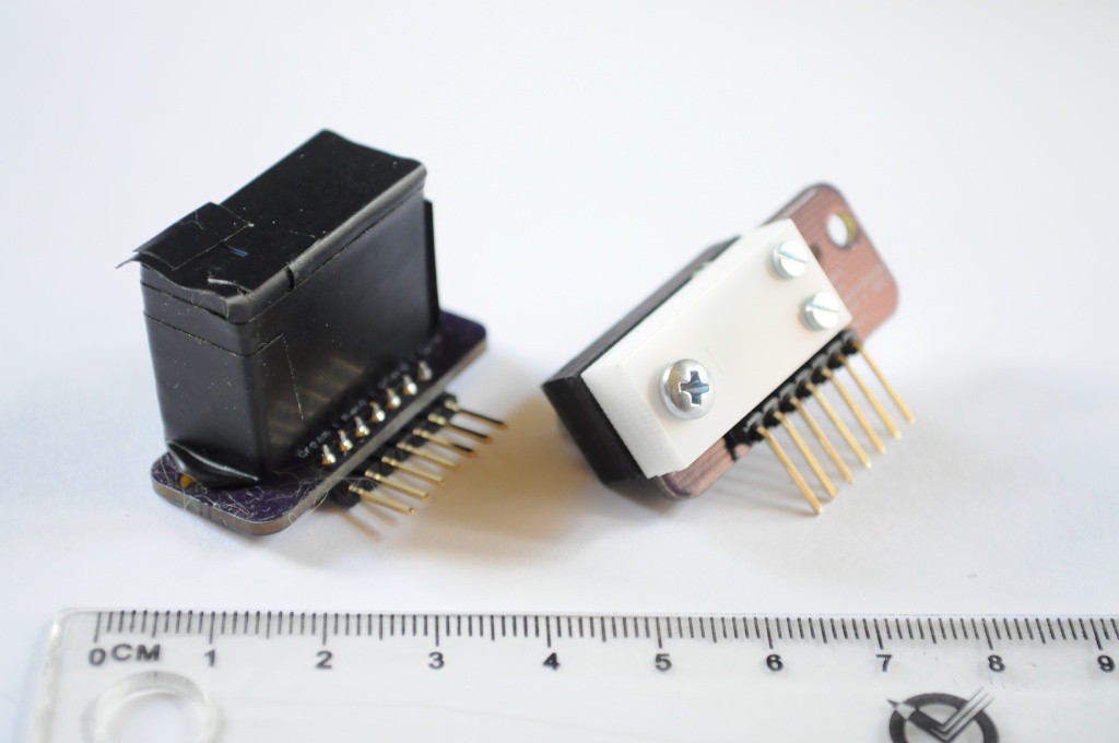
With most optical systems (especially spectrometers, where you're usually light starved and fighting a poor signal-to-noise ratio), it's important to have an absorptive light-tight matte black optical chamber that maximizes the chance that any stray light will get absorbed, and won't bounce around until it hits the detector. Aside from transparent plastic, the glossy white plastic I used here is probably the worst plastic you could build a spectrometer out of, so I spraypainted it flat matte black to reduce the noise.
Unfortunately this first iteration didn't yield a fantastic spectrometer -- likely from a combination of a poor grating with such a tiny chamber where placing baffles to capture the unused diffraction orders from the grating was nearly impossible. I think this means it's back to the transmission grating, and a bunch more iterating!
![]()
I'm also looking into off-the-shelf spectral sensors that might be suitable (and please feel encouraged to send in suggestions). While a very inexpensive open mini spectrometer is attractive, I'd be happy to include a more expensive sensor if it were off-the-shelf, fit the size requirements, and was reasonably capable.
It's important to remember how challenging this spectrometer miniaturization is -- above, the picture shows just how small I'm trying to miniaturize it to. That's tiny! And challenging, but I don't think impossible.
![]()
Part Selection
While most of the major components for the prototype Arducorder Mini have been chosen, I thought I'd highlight two cases where the final selection has a few alternatives.
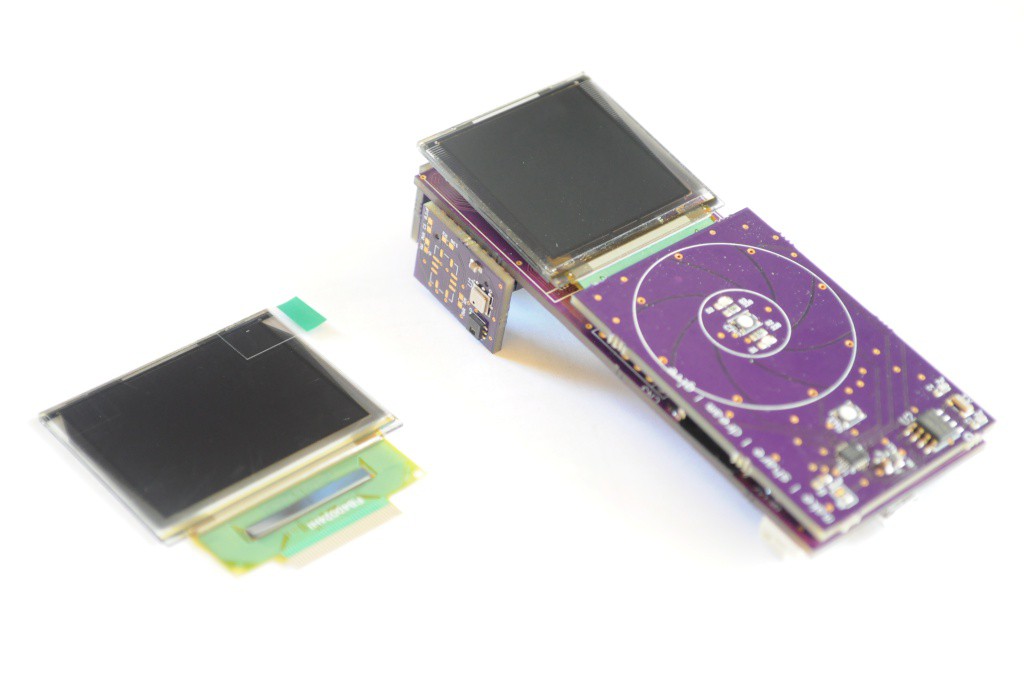
The main display uses a bright, beautiful Organic LED (OLED) display with 16-bit colour, and is about 1.5" diagonal with a 128x128 pixel resolution. When I first started developing the design concept about three months ago I also ordered some slightly larger displays to choose between. At 160x128, these displays offer a little more display real-estate, but with a lead time measured in months I knew this decision would have to wait until these arrived.
I have to confess that in the new months that this project has been active from concept to prototype, I've really fallen in love with the tiny form factor of the Arducorder Mini with it's 1.5" display. It feels very good to hold in ones hand -- not too big, not too small -- and the minimal memory requirements of the 128x128 display keeps things tractable. I remember reading an interview with the Raspberry Pi folks some time ago where they said that if they were constantly chasing new hardware features, they'd have never finished and released their first design. I feel the same here -- I'm not sure that adding a small amount of display area will substantially increase the user experience enough to change a working industrial design, or warrant the risk of using a long lead time part during development. It's also important to me to use parts that are easy for people to source and keep the barrier for entry as low as possible, and these 1.5" OLEDs are an inexpensive easy to source part with an estimated long lifetime, so I think the decision will likely be to continue to use the existing (and great!) display.
![]()
Another part that I'm having a bit of trouble selecting is the connector that goes between the motherboard and the radiation sensor board. I designed this to have a standard 6-pin 0.1" header, but didn't actually select the part before sending off the board, thinking that I'd be able to find a mechanically sturdy polarized locking connector without issue. I had this locking receptacle in mind when I designed the part (the same used for the Olimex ICD2 PIC programmer), but it turns out it's meant to be a board-to-cable connector, and I haven't been able to find a mating end that's board-mount.
Above is an alternative, which makes me mechanically a little nervous for this application because it doesn't have a lock to ensure that the two halves don't come unconnected, but seems to have a very good connection. Unfortunately the pins are looped and a little too big for the holes on the PCB, so this one's out too. I feel like I've looked at literally thousands of connectors and haven't found one yet, but hopefully I'll strike gold and find a suitable locking 10-12mm stacking height connector shortly.
![]()
Atmospheric Sensor Board Revision 1
Last but not least, I also put together the first revision of the atmospheric sensor board, and sent it off to OSHPark. This version adds 3 MOSFETs for the heaters on the MiCS-6814 gas sensor, which require more current than the PIC32 pins can handle.
Now that the WiFi module is working and much of the hardware seems to be in a good place (or moving towards minor revisions), I'm going to try and design a first iteration of the spectrometer sensor board to send off by the end of the week, and then start working on the user interface concept and implementing the beginnings of the graphical user interface!
Thanks for reading, and stay tuned!
-
Quick Update: Capacitive Touch Wheel!
08/12/2014 at 03:31 • 3 commentsA quick update -- the capacitive touch wheel is working great!
I've been working through verifying the hardware (since there's a lot of it), and ensuring all the critical hardware bits are working before shifting focus to the software and user interface. This is largely to make my mistakes cheaply -- it takes two weeks for new sets of boards to arrive, so it's important to figure out any issues sooner rather than later so that they can be sent out for another turn.
The capacitive touch board was one of the first of the half-dozen modular Arducorder Mini boards that I assembled, and one that I've been excited to get working -- it's the first capacitive touch sensor that I've designed. I mentioned that in an earlier post I'd had trouble contacting the MPR121 capacitive touch sensor on these boards, even after putting together several capacitive touch boards (with progressively less of the board populated, to try and isolate the issue):
![]()
Making expensive (in terms of time) mistakes
My normal debug process is to try and isolate the problem -- first to determine if it's a hardware or software issue, then narrow it down to figure out what's going on. Eagle footprints -- check. Schematic verified -- check. Three boards, three different MPR121 Arduino libraries, and one touch board jumpered to an Arduino Due later, the MPR121 still didn't appear to be communicating (while the real time clock on the same board seemed to be communicating fine). This is a really unusual problem, and I'd convinced myself that as unlikely as it was, it was possible that the MPR121 chips had simply arrived dead, or that they were particularly heat sensitive and not amenable to being reflowed in a toaster oven (although the one I hand soldered made this last alternative less likely).
To test this I ordered more touch boards (with slight revisions) from OSHPark, more MPR121 ICs from a different supplier, and an MPR121 breakout board from Sparkfun. The boards arrived this past weekend, and I put one together with the new parts -- same issue, it didn't communicate. I wired up the Sparkfun MPR121 breakout, and tried three MPR121 libraries (I2CDev, Sparkfun, and Adafruit, who just released one and a breakout to match) and two boards (Chipkit Max32 and Arduino Due) -- same issue. It's extremely unlikely that parts from two different batches would be bad, and the Sparkfun breakout board should be tested during assembly -- What was going on?
For debugging purposes, I decided to try the same code and wiring on an Arduino Uno, not because I had any reason to expect that it'd be different, but just to see -- being their flagship product, it was likely it'd work, and maybe there was something subtly different with the timings. And it did work! On goes the logic analyzer to see what's going on!
![]()
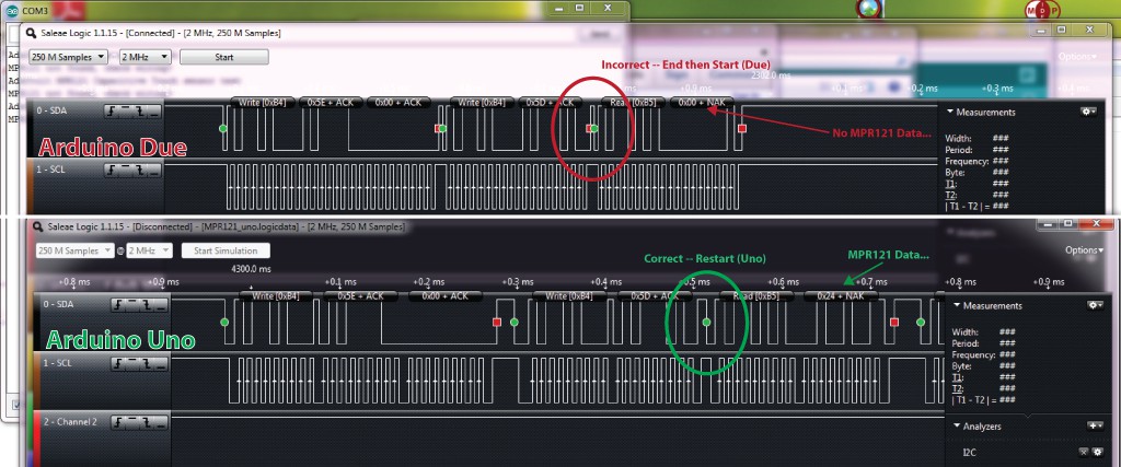
The MPR121 communicates over I2C, which is a two wire master/slave protocol with a bidirectional data line (SDA) and a clock line (SCL) that's clocked from the master. Above we see the waveforms for the first communication to the MPR121 using the Adafruit library, with the Due on the top, and the Uno on the bottom. The interesting thing is that the waveforms are nearly identical, and in both cases the MPR121 is acknowledging the communications by sending the ACK bit at the end of each transfer, but in the case of the Due (and Chipkit), the read commands are not returning data.
There is one notable difference in the waveforms for the Due and Uno -- during the command to read data from the MPR121, the Uno is correctly sending an I2C "Repeated Start" condition between telling the device it wants to read and actually performing the read, where as the Due is instead sending an I2C "End" followed by a "Start". In most cases that I've encountered this doesn't appear to be an issue, but the MPR121 datasheet clearly appears to show a "Repeated Start" condition for this transaction, so it's likely this is the culprit.
Both devices (Uno and Due) were using virtually the same code -- so why was the Due behaving differently? Some quick searching on the Arduino forum showed that this is apparently a known issue, that Repeated Starts are a new feature in the Wire library, and that they don't appear to be functioning correctly (or are unimplemented) for the Due. The Chipkit is based on an older version of the Arduino platform (I believe it's around Arduino 0023 compatible), so this feature hadn't yet been implemented.
I opened up the Chipkit Wire and TwoWireInterface (TWI) libraries and implemented the Repeated Start functionality exposed through the new Wire.endTransmission(sendStop:Boolean) function, and it ended up communicating and working fantastically! A software issue after all, but rarely do you expect that part of the issue lies with the peripheral libraries -- and it's a great opportunity to push the changes back to the latest Chipkit release so that other folks can benefit. Open source at work!
![]()
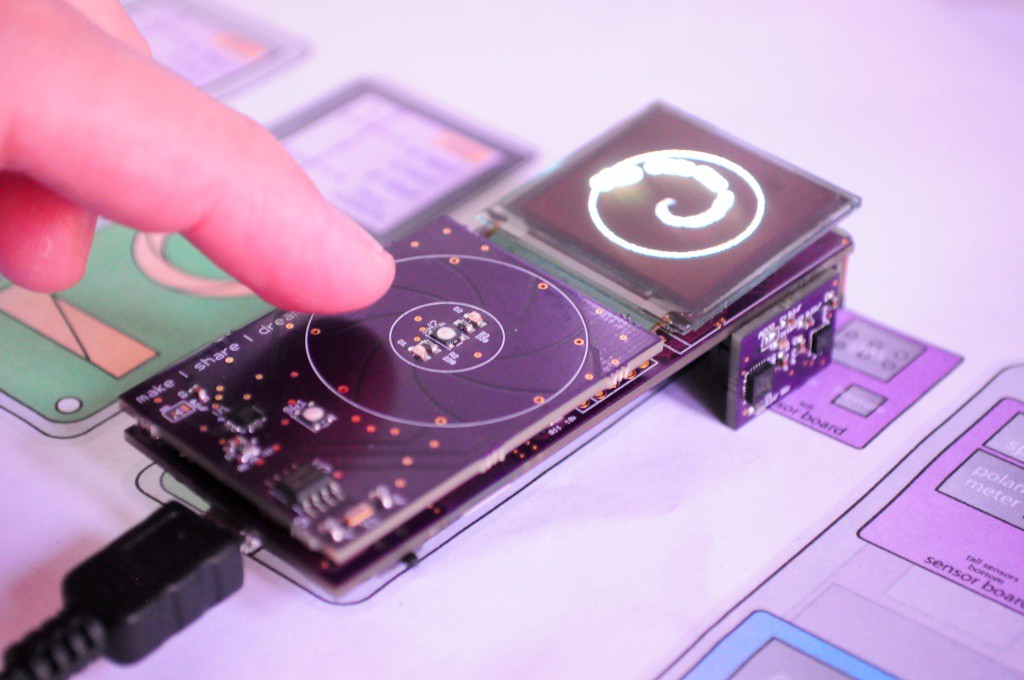
I've been expanding the Adafruit library (the simplest one that seemed to just work) with functionality for handling capacitive touch wheels, and calculating the touch angle by finding the center of mass on the N-electrode array, and seeing how it's distributed on the neighbouring electrodes. I wrote a quick visualization that would display this angle (pictured above, and in the video at the top), and it works beautifully! I opted to use an 8-electrode capacitive touch wheel to get as much resolution as possible, and it works far better than I had hoped -- it detects even very subtle changes in angle as you slide your finger around the wheel. Fantastic!
This is a major milestone, and now the Arducorder Mini can finally get some input instead of scrolling through test displays from various sensors automatically. I still have to implement some of the other MPR121 functionality to the Adafruit library, like GPIO buttons and LEDs, but now that I've verified the critical bits of the MPR121 and that the wheel is working, that's something that can likely wait a little bit while I move on to verify other hardware, like the CC3000.
Other Quick Updates (Hardware)
- MPU9150 IMU: I wrote some code to test the MPU9150 3-axis accelerometer/gyro/magnetometer using the I2CDev library, and to graph the 6 axes on the same coloured graph. It seems to be working great!
Open Mini Spectrometer / Thermal Camera board: I wanted to have this board sent off this week -- it's one of the sensor boards that I'm most excited about -- but it's also one of the most complex.
- Open Mini Spectrometer: I've been trying to redesign this to lay the whole spectroscope down (so requires less height), improve the spatial translation invariance, potentially move to a more sensitive detector, and potentially move to a laser-cuttable design (with a ~0.2mm laser-cut slit). I've also been trying to avoid as many prescription-ground optical surfaces as possible, which add fantastic amounts to the cost. Some very tiny and inexpensive front-silvered mirrors arrived today, so I'm excited to get back to this. I have to be careful though -- the first open mini spectrometer was designed in an afternoon, and this new version has to be kept tractable and similarly inexpensive. I think rapid iteration is especially important here -- I'd rather get something running end-to-end quickly than take months to work out the perfect spectroscope and leave the new version untested for so long.
- Low-resolution Thermal Imager: I'd initially planned on using the MLX90620 16x4 thermal sensor, both because it looks to have great thermal/resolution characteristics, and (until recently) was really the only game in town for the sub-$100 imager price range. Recently the Panasonic Grid Eye 8x8 array, as well as a similar (but slightly larger) offering from Omron have popped up. A really great Inexpensive Thermal Imager project arrived on Hackaday.io recently, and I've been really impressed that he posted his evaluations of each of these three sensors to verify their thermal characteristics. In his tests, the Omron appears to come out as the most stable, followed by the smaller Grid Eye and the MLX90620, both having largely similar characteristics despite the Grid Eye being half the price. I'd started redesigning the Spectrometer/Thermal Camera board to use the Grid Eye instead, only to find that they're out of stock nearly everywhere, and additional stock doesn't look like it'll arrive for another 3 months -- way too late for me. I think the Omron is too big, so it's back to the MLX90620, which still looks to be an excellent sensor with a larger temperature range than the Grid Eye, and a large range of framerates.
Github
In preparation for the Hackaday Prize Quarter Finals, I've been preparing to put all the source files (as they currently are) on github. Since the HDP quarterfinals now only requires a single video that shows the prototype, I'll likely use the Arducorder Mini Project Concept Video that I put together for the first deadline a few weeks ago, since shooting the videos is so fun that it ropes me in for much longer than I should spend on it -- I'm only one person and there's plenty of code and hardware left to develop! :)
Speaking of which, the other night I was /dreaming/ about writing code (this is usually a sign that I need to take a few days off), and my alarm went off before I'd had the chance to finish it. In my half-asleepness, I grabbed my alarm and set it to half an hour later so I could go back to sleep, finish up the code, and commit it to github before waking up again. Made the whole lab at school laugh this morning. You know you're committed to open source when... :)
Thanks for reading, and stay tuned!
-
Sensor Board Mega-Update!
07/29/2014 at 06:14 • 4 commentsA big update with lots of pictures -- I've been building and testing many of the first revision sensor boards.
Watching the PWM of your soldering station's power supply!
![]()
One of the things I remember most from building the Open Source Science Tricorder Mark 1 is that the moment I had it built and programmed -- around 2am, late one weekend, doing laundry at my parents house in the finest grad student tradition -- I immediately looked around for things to sense. The magnetometer visualization on the Mark 1 was always my favorite, and holding the Mark 1 up to a wall-mount power supply I was able to see the fields of the transformer bouncing back and forth, only moments after finishing the device. Definitely very cool, and very memorable. Years later we were hunting down some high magnetic fields in a mens washroom under an NMR lab at school, which is probably the second most memorable (and probably one of the most hilarious) moments of science I've had.
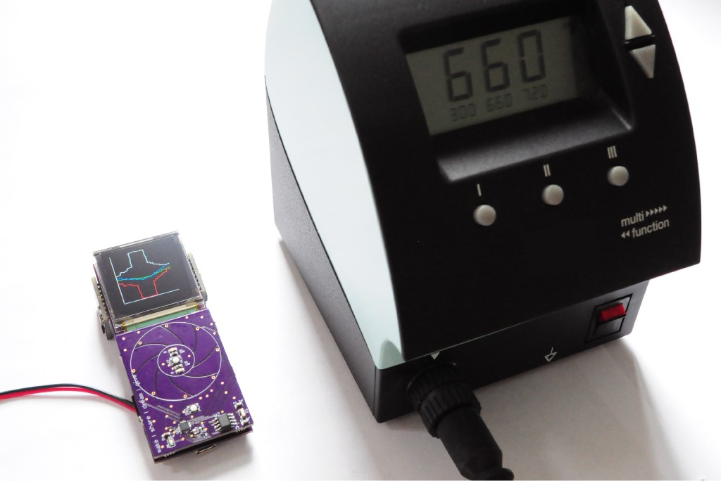
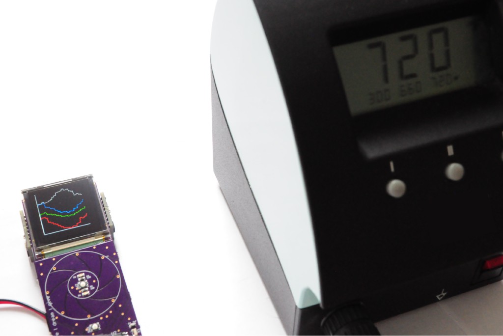
I decided that, with many of the Arducorder Mini sensor boards up and running, and a basic multi-series graph visualization plotting the x, y, z (RGB) and total (white) field strengths from the magnetometer, that it'd be interesting to place it near my heavy soldering station -- heavy from a big transformer in its base -- and see what we could see.
![]()
The solder station works by pulsing the heater on the soldering iron to keep it at a set temperature. When the internal temperature sensor reads the iron is too cold, it likely pours on the juice to keep it at a given temperature. The neat thing is that this appears to happen in discrete chunks of time a second or two apart -- looking at these two pictures, we can see a roughly sinusoidal magnetic field strength (white line) from the transformer -- my first guess is that this is that this is the 60Hz line frequency aliased by whatever the sampling frequency is of the magnetometer here (about 20Hz). But, in the first picture, something really interesting is visible -- the field strength suddenly shoots up for half a second, likely signifying that the soldering station has engaged the heater on the iron. Very neat to watch!
And here's a quick video I took while testing the magnetometer (and microphone -- the purple series).
![]()
Modular Sensor Boards
I try to make my mistakes cheaply, so recently I've been building as many of the first-revision boards to verify their functionality, and note any issues or modifications for the next revision. Pictured here (above) is the sensor board that contains the lightning, UV, and audio sensors (front), and the atmospheric sensor board that contains the atmospheric sensors like temperature, pressure, and humidity (right).
![]()
The same view, but here I've just waved a pair of piers that are slightly magnetic near the Arducorder Mini to show the simple multi-series graph widget. There's still a great deal to do on this widget, but it's a good start for easily graphing a few related sets of data, and the autoscaling feature means it's entirely hands free.
![]()
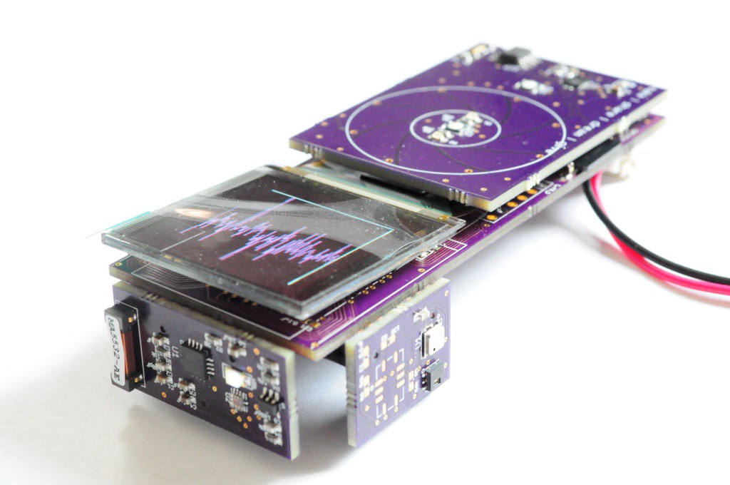
To verify the functionality of the microphone, I wrote something that would pipe the data to a graph, and started singing to watch the waveforms. (Actually, the first thing I did was to put on some music with a beat, put the Arducorder Mini up to the speaker, and see if I could watch both the audio waveform and the magnetic field from the speaker, but I think I'd have to look at the data a little closer or plot it overtop of each other to verify that the field strength changes were correlated with the audio amplitude). Still, very cool for something that's just starting!
The UV sensor also looks to be communicating okay, and the data changes when I place my hand over it, but it'll need a bit more work to verify the measurements. I didn't happen to have a storm handy to test the lightning sensor, but the breakout board I have seems to be particularly good at detecting whenever the air conditioner turns on, so I'll have to work with that until a storm rolls in. :)
![]()
High-Energy Particle (Radiation) Detector Sensor Board
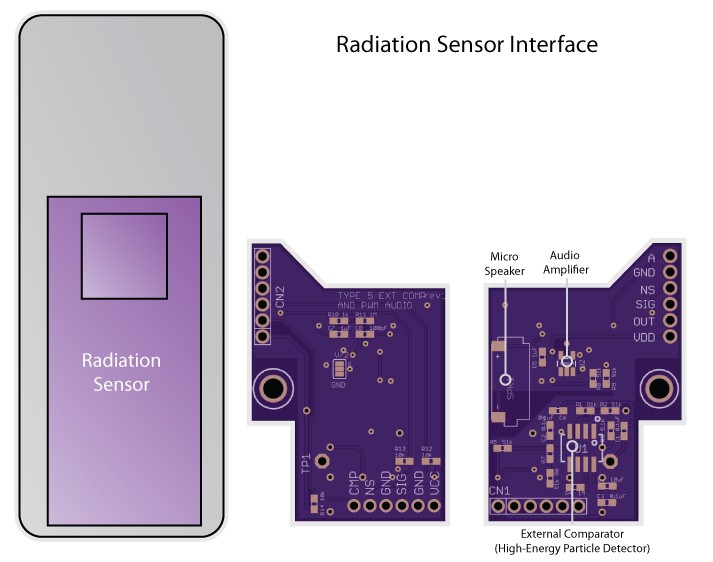
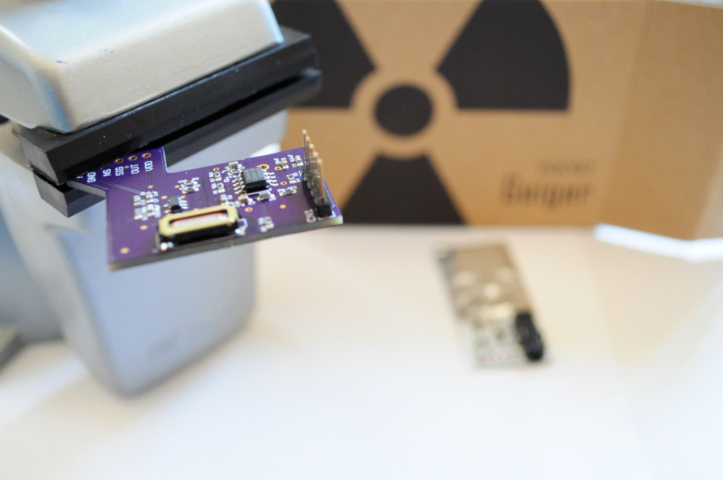
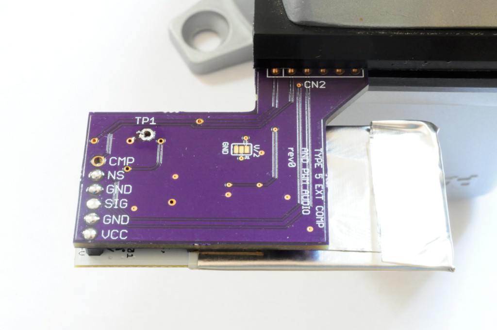
One of the biggest items on my open source science tricorder wishlist has been a high-energy particle detector, so I'm very happy to include the super-sensitive Radiation Watch Type 5 detector on the Arducorder Mini. The backpack board I've designed for it (above) includes the same external comparator that I added for the Open Source Computed Tomography (CT) Scanner project, so that it extends the range of the sensor to detecting lower-energy x-rays down to around 33keV.
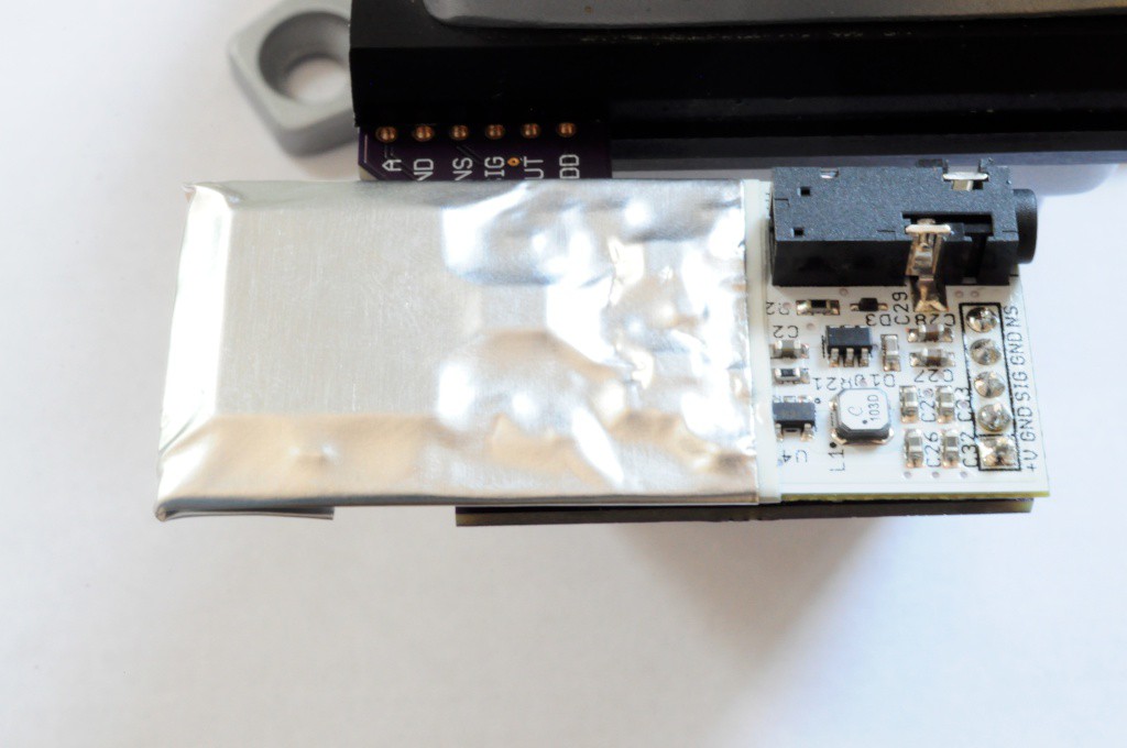
This board also happens to house an extremely tiny speaker and audio amplifier so that the Arducorder Mini will be able to play back sound, which is one of the most popular feature requests I've had. The speaker is on this board for no other reason than that at 6x12mm it's still relatively large (compared to the other components), and space is at a premium on the motherboard.
![]()
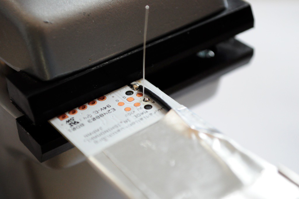
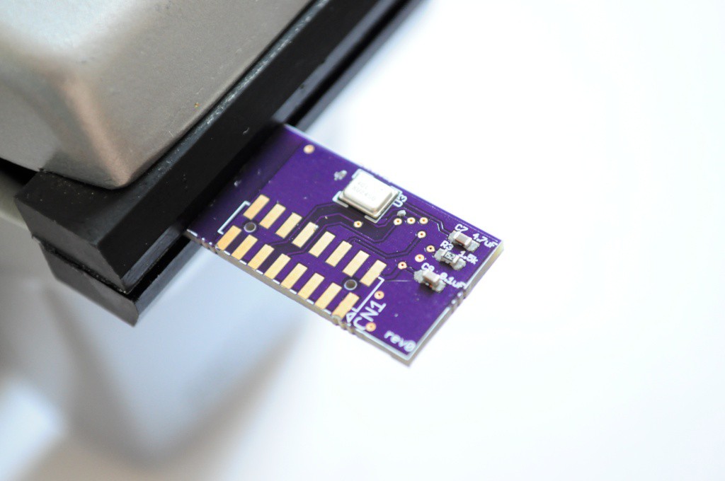
For the backpack to make the Type 5 extra sensitive, it has to take the raw amplifier output from a test point on the Type 5 and connect it to an anchor point (TP1) that's directly above on the backpack. There's a 5 pin header that has to be soldered, which gives access to the less-sensitive regular output of the Type 5, and the noise output, which senses vibrations (which means the sensor output is invalid).
![]()
It all came together very well, and looks great!
![]()
Though I'm still looking for the perfect connector that's polarized, locking, mechanically sound, and exactly the height that would keep the Type 5 one lithium-polymer-batteries height off the motherboard, I was able to test the Type 5 with some jumpers. The result was 5cpm using the regular output, and about 20cpm with the super-sensitive output, and both went up substantially when bringing a 1 uCi Cadmium radioisotope check source near the sensor. Looking great!
Cat!
![]()
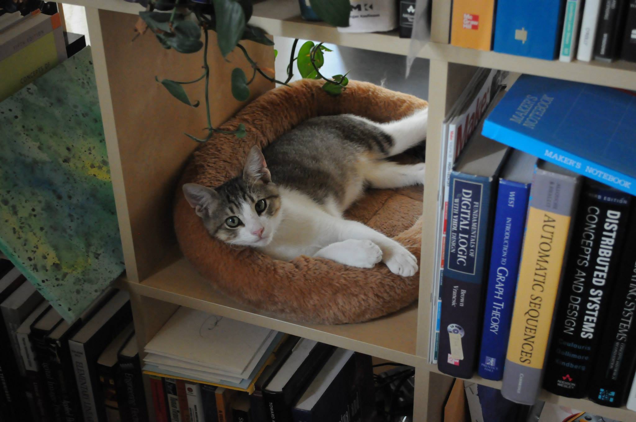
A brief interlude -- both of my cats love Digikey boxes, and usually race to sit in the cushy packing material. If they fits, they sits.
![]()
Lightning et al. Sensor Board
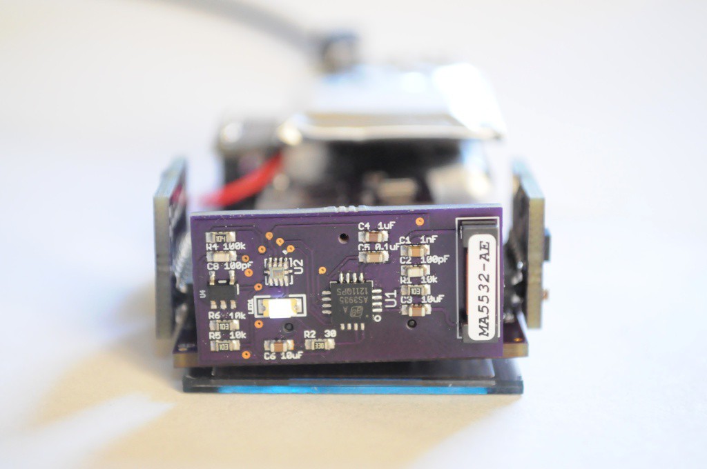
A few pictures from assembling the Lightning et al. sensor board, which contains the AS3935 Lightning Sensor from AMS, the SI1145 UV sensor from Silicon Labs, and the ADMP401 MEMS microphone from Analog (as well as an amplifier circuit). Above is the ADMP401, on the back (inner-facing)side of the board.
The tricky bit about the Lightning board isn't that it's double sided, but that it's double sided with leadless parts on both sides. I try to avoid this, usually putting all leadless packages on one side, putting the board through only a single toaster-oven reflow cycle, and then working through all hand-solderable packages on the other side. This wasn't easily possible with the lightning board, so I decided to give double-sided toaster oven reflow my first try.
![]()
Here you can see parts on both sides -- most of them on the top, and the ADMP401 on the bottom.
![]()
The double-sided toaster oven reflow worked famously. I populated and reflowed the ADMP401 first, and then populated and reflowed the top of the board (placing the board upside down on another PCB, so the heavy parts wouldn't fall off on the second reflow cycle),
![]()
Looks beautiful!
Atmospheric Sensor Board
![]()
I also populated, but haven't had time to test, the atmospheric sensor board. While I populated the atmospheric temperature, pressure, and humidity sensors, I realized the the current draw for the MiCS gas sensor is more than the PIC32 pins can source, and that it needs a second revision with some mosfets to ensure that it won't blow up some of the IO pins on the microcontroller. This is exactly why I'm building these first revision boards as soon as possible -- to find out what I forgot as I was building them.
![]()
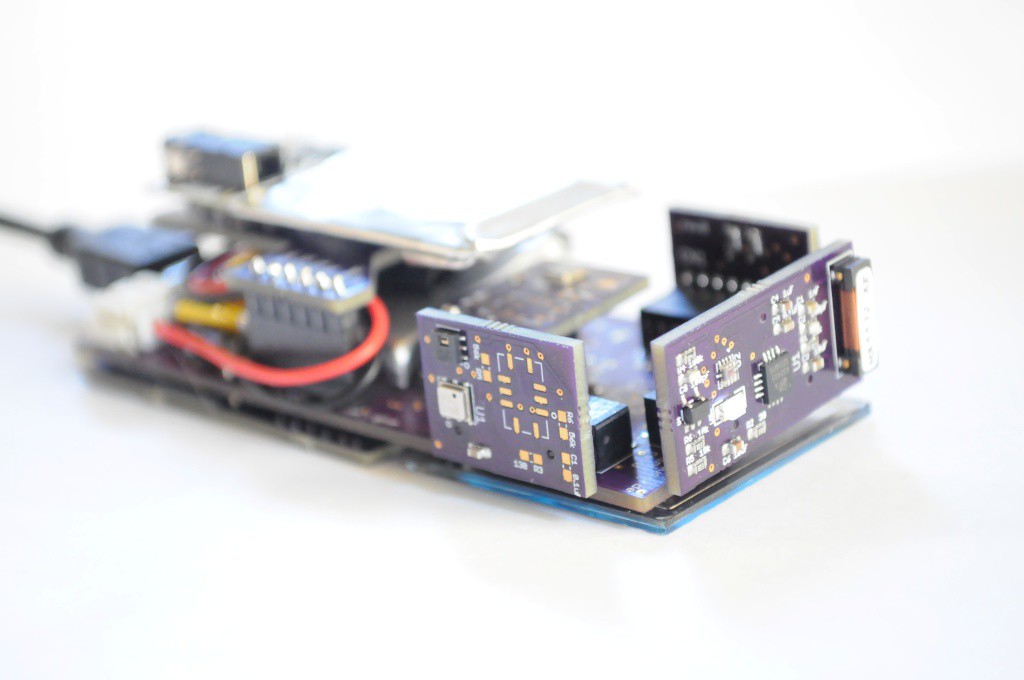
Modular Sensor Suite (6 of the 7 Arducorder Mini boards)
Above is a set of 6 (out of the 7 total) sensor boards. I still have to design the most exciting board, the spectrometer / thermal camera board, and wanted to hold off until I'd assembled the rest of the Arducorder Mini to get an idea of size constraints, and if I can redesign the open mini embedded spectrometer to make it even smaller, and reduce the thickness of the entire Arducorder Mini.
![]()
Here three of the modular sensor boards are visible, with the spot for the fourth -- the spectrometer/thermal camera board, still unpopulated. The connector for the high energy particle detector can be seen on the bottom right side.
![]()
Capacitive Touch Wheel Board
Last but not least for this update, I'm eager to begin working on the user interface, and have populated several of the MPR121-based capacitive touch wheel boards. Unfortunately while I've had success contacting the real-time clock on the touch board, I haven't had any luck contacting the touch sensor. I've built three of the boards without luck (two using toaster oven reflow, and a third hand soldered), and have double-checked the footprint, schematic, soldering, and code, without luck. I'm fresh out of MPR121 ICs and touch boards, so I've ordered additional boards, MPR121's from a different source (incase the chips were dead), and a breakout board to hand-wire to the capacitive touch wheel in the mean time.
Next Steps
There's been a great amount of progress recently, and my focus for the near-term is to verify the hardware, and send out any revisions that are necessary. While those revisions are out, and once the hardware is reasonably stable, I can start to really push on the design of the user interface. I've had lots of ideas for an simple and intuitive visualization interface for sensor data, so it'll be interesting to finally put code to practice.
Already the prototype Arducorder Mini feels wonderful to hold in your hand and walk around detecting things, so I'm very excited to see how it takes shape in the coming weeks and months.
Thanks for reading!
-
First Sensor Boards
07/16/2014 at 06:42 • 5 commentsA bunch of the sensor boards arrived this week! I confess that holding them in your hand is a lot different than seeing them in Eagle CAD -- these new sensor boards are tiny.
Modular Sensor Boards
![]()
The first three (of five) sensor boards arrived, with the radiation sensor board (and the touch interface board) arriving a few days later. The spectrometer board is the only sensor board that still has to be designed, and I'm waiting on laying it out until I have a better idea of how the radiation sensor board fits on the back. The spectrometer is the largest sensor in the device, but if there's room I might be able to lay it down and make the entire device even thinner -- definitely worth holding off a few weeks on.
The first thing that struck me is that these sensor boards are *tiny* -- much smaller than any of my previous boards. They're about the size of the tip of my finger! I think the idea of utilizing as much real estate on the outside of the device as possible for sensors (rather than just having them all face towards the front) is really a fantastic design idea for keeping the device small.
![]()
These boards are so tiny that they're a bit of a challenge to attach a solder stencil to. Since invariably many of the parts I use end up having very fine pitches (0.4 to 0.5mm), my favorite method of stenciling is to clamp the board and stencil in a clamp, adjust it so it's aligned, then squeegee on some solder paste.
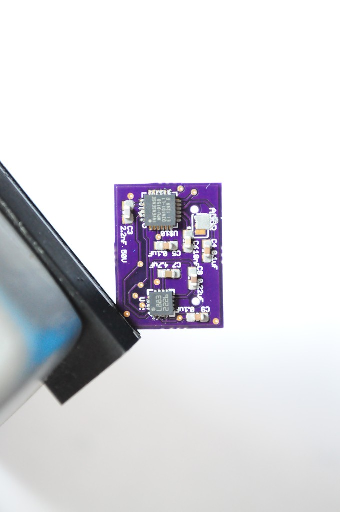
Here, the sensor board combining the Honeywell HMC5883L 3-axis magnetometer (left) and the Invensense MPU9150 9-axis accelerometer/gyro/magnetometer (right) is being assembled.
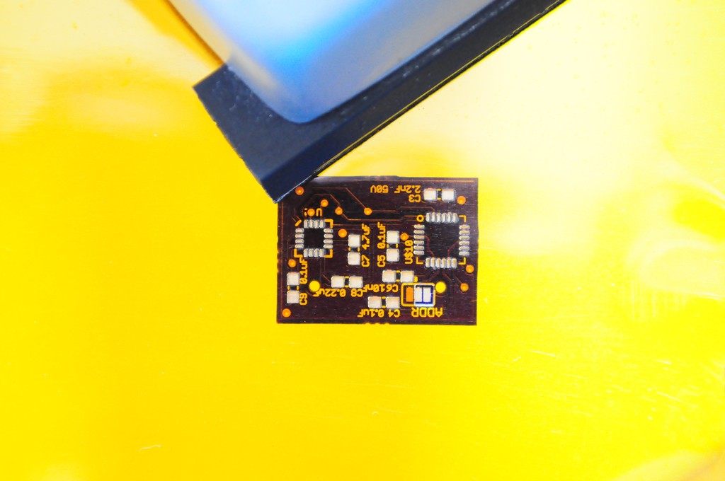
![]()
Here's the board, with solder paste. Looks good! The paste on the MPU9150 is a little misaligned by a few tenths of a millimeter, but it tends to sort itself out during the reflow process. I usually adjust some of the more worrisome looking misaligned paste around with a pair of tweezers before placing the components.
![]()
Here's the board with paste and after the components have been placed. Time for reflow!
![]()
I tend to reflow most of my boards in a $20 toaster oven. It sounds crazy the first time you hear it, and you feel crazy the first time you do it, but it usually works out very well. Sparkfun has a tutorial on converting toaster ovens into reflow ovens, but I live a little more dangerously and just set the heat to maximum and bake -- watching the board like a hawk until it reflows, and then popping it out of the oven immediately after.
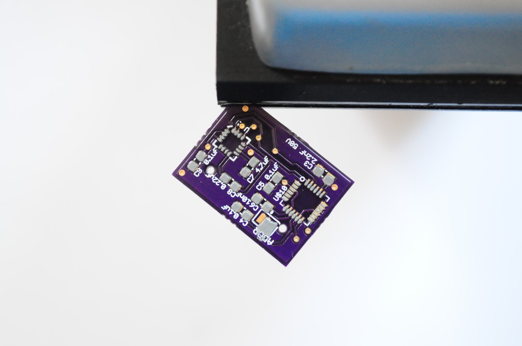
![]()
These sensor boards are /so small/ that they will fall through the grill of the toaster oven, so I've layed this one on an old coaster -- er -- breakout board from another project. I'm also trying not to snap pictures for too long, since I have to pull it out as soon as it reflows or the parts will cook!
![]()
The finished magnetometer and inertial measurement unit sensor board. Not shown was attaching the sensor board connector to the back of the board -- a 20 pin double-row 2mm-pitch male connector.
![]()
I hadn't yet soldered on the sensor board connectors to the motherboard, in part because they were low on stock, so I could only order enough for a few boards. These have alignment pins that go through the board (and make routing a little more challenging), but it's worth it -- they align in exactly the correct, orthogonal orientations.
![]()
I confess that one of my largest anxieties about this design was the sensor board connectors. I literally looked through thousands of connectors on Digikey searching for one that was both right-angle, board-to-board, medium-density, strong enough to firmly mechanically support the sensor boards, and larger than a 0.5mm pitch for easy alignment and soldering. There were not many options. The ones I settled on looked like they would have /exactly/ the right mechanical clearance if the board could be routed within 10 mil of the connector footprint, which is a little tight and the first time I've had such a tight clearance, but it ended up working out famously.
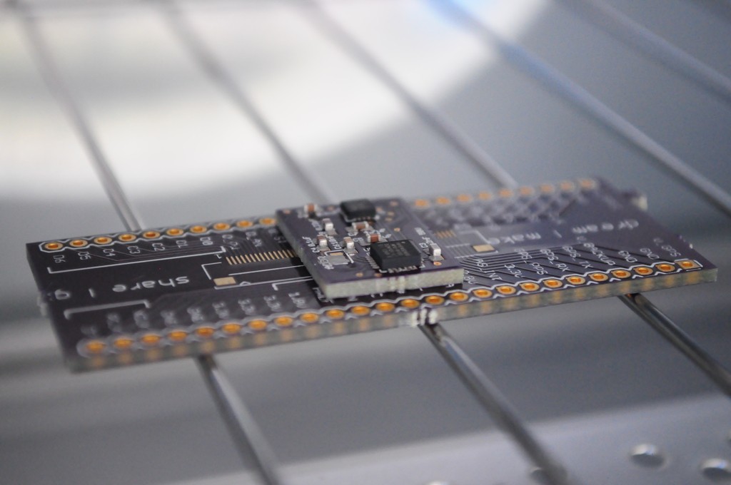
![]()
Here's the first sensor board of the Arducorder Mini! It's connected to one of the 4 interchangeable sensor module connectors on the top, and just waiting for some software to test it!
![]()
Software
I wrote a quick test for the magnetometer to verify that measurements were coming out correctly, then went to work on writing a bit of software to encapsulate and display the data, and lay the very beginnings of a test user interface.
To help architect the software in a way that keeps it easier for other folks to modify, maintain, and use in other projects, I wrote the beginnings of a few modules:
- A framebuffer driver (with a backbuffer) for the ER-OLED015-1 1.5" OLED display, which is 128x128 pixels and 16-bit colour. This is a popular display in the OSH community, and most folks seem to be using it over SPI with Arduinos. Because the total frame buffer size would be 128 x 128 x 2bpp = 32k, most Arduinos don't have the capacity to store this framebuffer, and have to address the display pixel-by-pixel over SPI, which reduces the framerate, the kind of rendering you can do, and ultimately the user experience. The PIC32 used in the Arducorder Mini has plenty of RAM for the framebuffer (128k), and it's connected to the 8-bit parallel master port so that it can the display can be updated very quickly. I haven't precisely measured it, but I believe it's currently updating in the neighbourhood of 50-100fps, which is very good.
- A framebuffer graphics library that supports quickly writing basic graphics primitives (lines, circles, triangles, etc) to the framebuffer. To help make these functions more familiar to folks and easy to pick up I've started with the popular Adafruit graphics library, and am extending it as required.
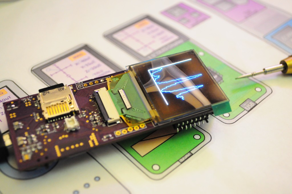
- A graphing and visualization library for attractively graphing and displaying data in a variety of ways, with configurable options. This is a work in progress and something I'm very excited about, and the other night wrote the first widget -- a very basic graph with autoscaling (picture below, and in video). It's not terribly attactive right now, but the back end is all there.
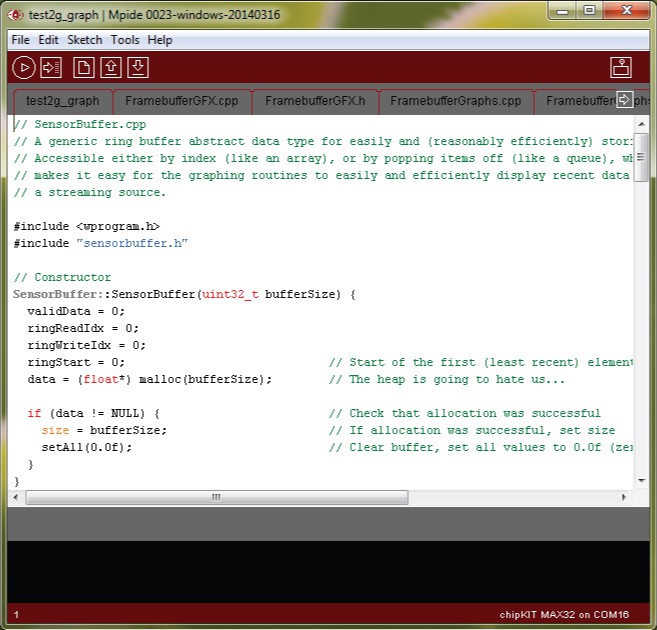
- A sensor buffer storage class, for efficiently storing, using, and visualizing data (through the graphing and visualization library). Memory is a huge concern on microcontroller-based embedded systems, but I'd still like to be able to constantly record data from all the sensors in a buffer so that it's always "recording", and you can worry about discovering and analyzing the data rather than fumbling to try and save it while something interesting is going on!
There are also a few minor challenges that have some up using the standard Arduino libraries. The Chipkit port of the Arduino core to PIC32 is currently only compatible with Arduino 0023, rather than the newer Arduino 1+ standards. Some of the libraries for SPI also appear to be a little different. This is making some difficulties:
- SD card read speeds: From my game programming days, I learned that a lot of 2D graphics on PCs are rendered by having a large repository of bitmap graphical resources, and loading them (or "blitting" them) to the framebuffer. This has a lot of advantages -- instead of being limited to drawing your graphics in code using graphics primitives, you can use a professional illustration program and simply load in the results. This is what I'd planned to do with the Arducorder Mini, blitting bitmaps from the SD card (since there isn't enough RAM in the PIC32 to store more than one or two at once). There's a small hangup, in that the standard SD card library for the Chipkit has a read speed of only around 100k/second, which is a little slow, and much less than the ~2,500k/second theoretical maximum for an SPI bus running at 20Mhz. This makes the bitmap load time on the order of a second, when it needs to be about 10 times faster to really use this technique. Potential Workaround: There is a much faster SD card library called sdfat that is written for the Arduino 1.0+ libraries, but hasn't yet been ported to the Chipkit. I spent an evening trying to port over an earlier Arduino 0023 version without much luck (there is no debugger in the Arduino IDE, which is completely okay for a learning platform, but it makes me weep for serious library development). I'll have to revisit this.
- CC3000 library: The popular library to interface the Arduino with the CC3000 appears to be the Adafruit CC3000 library, but isn't currently Chipkit compatible. I'll likely have to port this as well.
![]()
Putting it all together
And here it is, all put together and with some very first test software. Looks great!
Concept Video
This week I also put together the first video for THP describing the concept behind the Arducorder Mini. It was a lot of fun to put together, and I hope you like it.
Thanks for reading, and stay tuned!
Open Source Science Tricorder
Science in your hand. A pocket-sized instrument capable of visualizing and exploring the world around you.
 peter jansen