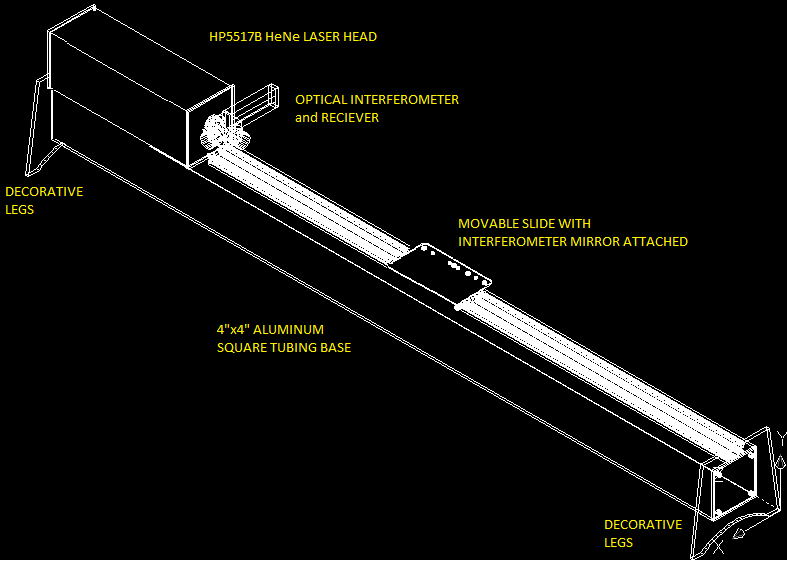
The hardware that will be integrated together and their purpose is:

- HP5528A Laser interferometer measuring system.The laser interferometer is the primary measuring instrument for this overall project.It is capable of resolving the motion of a movable mirror to within 0.000001 inches or 0.00001 millmeters.This laser interferometer is an older model instrument, but I believe the system is in good condition and completely functional.I believe it is reliable and might even be able to be calibrated.This laser interferometer consists of a HP5508A measurement display/controller/power supply, a HP5517B HeNe laser head, HP10780 remote receiver, and an optical Michelson interferometer consisting of the following part numbers; HP10706A beam splitter, (2) HP10703A retro reflectors and a ¼ wave plate.
- Zipit Z2 embedded palmtop computer running openwrt.This computer will be programmed and wired to a set of temperature sensors to measure the material temperature of an object being measured, an additional set of air sensors for temperature, humidity and barometric pressure, which will be used to automatically calculate the speed of light in the air surrounding the interferometer.The Zipit Z2 will also be wired to a Prologix GPIB-USB Controller for communications back and forth between the HP5508A and the Zipit Z2.The Zipit will send GPIB commands to the HP5508A after calculating the average temperature of the material temperature sensors as well as the speed of light value.The Zipit Z2 will also be used as HTML server.It has a WiFi interface, which allows measurements to be displayed remotely on a browser with access to my network.The HTML server will also provide an interface to control the HP5508A remotely.
- The linear track and carriage are assembled from a turn-key solution provided from the following web site. https://www.inventables.com/projects/simple-camera-slider#overview The movable retro reflector for the laser interferometer will be bolted to the moveable carriage.Also the remainder of the optics will be bolted to the rail itself.The rail lends itself well for bolting additional fixtures for holding clamps and such for attaching objects to be measured.
This measuring machine will work in the following manner.A laser interferometer will be arranged so that the moving mirror of the interferometer will be attached to a movable slide attached to a linear aluminum rail.The movement of the slide on the rail will then be directly measured by the laser interferometer.The laser, electronic receiver, optics and the linear rail will be bolted to a 4”x4”x90” square aluminum tubing.Additional fixtures will be constructed to hold items to be measured in place against the linear rail.The movable slide will be moved from a fixed reference position to a point where it makes contact against the item being measured.

- The laser interferometer has a centralized electronic control box known as a 5508A Measurement Display.This unit does the following
- Provides power to operate the Laser Head and Optical Receiver
- Converts measurement information into a number that represents a unit of length
- Provides the control and display interface for the person operating the interferometer
- Provides electrical interface for material temperature sensors and environmental sensors
- Provides a GPIB interface
The rear of the 5508A has several electronic connectors for the original temperature sensors designed for measuring the temperature of the object whose length you are measuring.There are connections for each three individual temperature sensors.The 5508A will operate with zero, one two or three sensors hooked up.The 5508A will calculate the average of the temperatures measured.The average temperature is used with the coefficient of thermal expansion to figure out how much change in length there would be if the thing you are measuring was currently at a standardized temperature.If there are not temperature sensors attached to the 5508A, then you can manually type the temperature from the keyboard on the front.Finally the temperature can also be entered from the GPIB interface.
For this project I will use a Zipit Z2.The Zipit will have three i2c temperature sensors.Each of these will be wired to the Zipits external docking connector, where the i2c connections can be accessed.The sensors are calibrated and a lookup table was created so that temperature sensor values are correlated to the temperature measured by an external digital thermometer.An awk script will lookup the temperature after the i2cget command returns a value.Each of the three temperature sensors work in this manner.The average of the three sensors are then transmitted back to the 5508A by using the echo command and sending the output to a USB-to-GPIB adapter.
 Beaglebreath
Discussions
Become a Hackaday.io Member
Create an account to leave a comment. Already have an account? Log In.