Close
0%
0%

repurposed luminiferous aether detector

over the last few years, i've build up a functional laser interferometer. now i want to use it to accurately measure distance.

Similar projects worth following
Over the last few years I have purchased most of the parts needed to make a functional laser interferometer. My goal for this project build a measuring machine to be used to calibrate gage blocks as well as other accurate measurements. I hope to be able to achieve reliable and accurate measurements with a range of 60 inches and with an uncertainty 0.000005 inches This project consists of three smaller projects.

The smaller projects are
1. getting the interferometer optics and electronics working.
2. building a computer and sensors to calculate automatic correction factors for the speed of light in air, and gage block length corrections due to temperature changes.
3. building a linear motion rail and measuring jaws.

On this site I will describe the current condition of this project as I struggle to build it over the next few weeks.

I learned about the Michaelson Morley Experiment about 20 years ago in college.  At that time we also built a Michaelson interferometer on an optical breadboard.  I was amazed at the sensitivity of the interferometer.  Even with the optics levitated on pneumatic isolation legs on the optical bench, we could easily see people's foot-falls from the hall way outside of the lab and we could see vibrations caused by trucks driving down the road outside.  A few years ago I read an article about commercially made interferometers.  I became enamored the HP5528A laser interferometer manufactured by Hewlett Packard in the 1970's.  I became interested in building a linear measuring machine which would be capable of making calibrated length measurements

  • 1 × HP5508A measurement display
  • 1 × HP10780 reciever
  • 2 × HP10703A retroreflector
  • 1 × HP10706A plane mirror interferometer
  • 1 × HP5517B laser

View all 9 components

  • steel table under construction

    Beaglebreath10/30/2014 at 17:43 0 comments

    All righty, it has been a while since I posted an update. As of this morning, I've got the zipit and it's electronic hardware more-or-less operating and sending speed of light information back to the interferometer. The zipit is displaying sensor data and interferometer readouts on a simple web page. I will style up the web page in the near future. This is reliable enough for me to start working on the layout table.

    I have ordered a 500 pound, 45"x16" steel layout plate with 5 t-slots running the length of the plate. Once it gets here, I have hired a machinist to cut a 1/2 inch wide slot through the middle of the plate. He will also build a steel table to place the plate on.

    On the underside of the steel plate I will place the moveable optics of the interferometer. They will be mounted to moveable jaws. The moveable jaws will be shaped similar to the jaws of a caliper. The measuring points of the jaws will be inserted through the 1/2 inch slot from below the plate. The two measuring points will be able to be moved in the slot and will provide the ability to make inside and outside measurements.

  • holy guacamole! it actually works...

    Beaglebreath09/03/2014 at 16:26 0 comments

    I've been busy as a one armed hat rack for over a month now and haven't taken much time to work on this project.  Finally, I was able to spend some quality time with the interferometer over the three day weekend.  I have created a new flowchart of how the software will interact with the interferometer, and I rewrote some of the older i2c code, now that I have learned some new tricks.

    Anyway, last night after writing c code and a shell script, I was able to have the Zipit calculating the index of refraction of light once every six seconds.  after a little more scripting, I was able to transmit the updated index of refraction to the interferometer.

    To my delight, I saw that the interferometer began to agree with my digital caliper across it's total range.

  • Overview Video

    Beaglebreath08/20/2014 at 19:08 0 comments

  • html server

    Beaglebreath07/14/2014 at 07:43 0 comments

    the primary reason I chose to use this distribution of openwrt is for the node.js scripting, which will allow me to provide an html server and be able to run shell scripts.

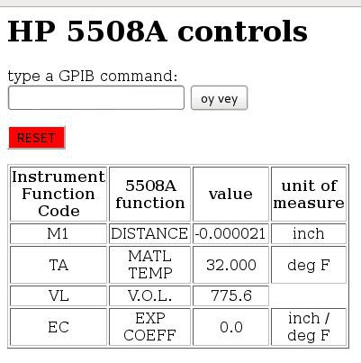
    Here is what the web page looks like so far.

    This is my first journey into java script, and here is what I have so far;

    • When a client accesses the web page, and makes a POST request, the server sends the client the web page shown above.
    • Then a couple of shell scripts are executed.
      • The first script runs some i2c commands to get the latest data from the environmental sensors and calculates the speed of light.
      • The second script communicates with the HP5508A over the GPIB adapter.
      • The third script knits together a new HTML file to send to the client the next time it makes a POST request.

    There are a bunch of problems with this approach, but it at least has given me a first step toward accomplishing something.

  • pcb's for the temperature sensors

    Beaglebreath07/11/2014 at 08:00 0 comments

    I will use a total of four MCP9804 temperature sensors. They will provide the temperature of the object being measured and the air temperature.

    Sensors on an i2c bus have addresses to differentiate one sensor from another. The MCP9804 can be addressed by changing the wiring on three of the pin connections of the sensor's case. Applying voltage to a pin sets a bit high for the address logic in the sensor. I have designed a set of circuit boards which have set the address pins to different values for the sensor attached to the circuit board.

    This table shows the name of the sensor, description of it's use and the i2c address.

    NAMEDESCRIPTIONi2c ADDRESS
    TA

    Air Temperature

    0x1c
    M0Material Sensor 0
    0x1f
    M1

    Material Sensor 1

    0x1e
    M2

    Material Sensor 2

    0x1d

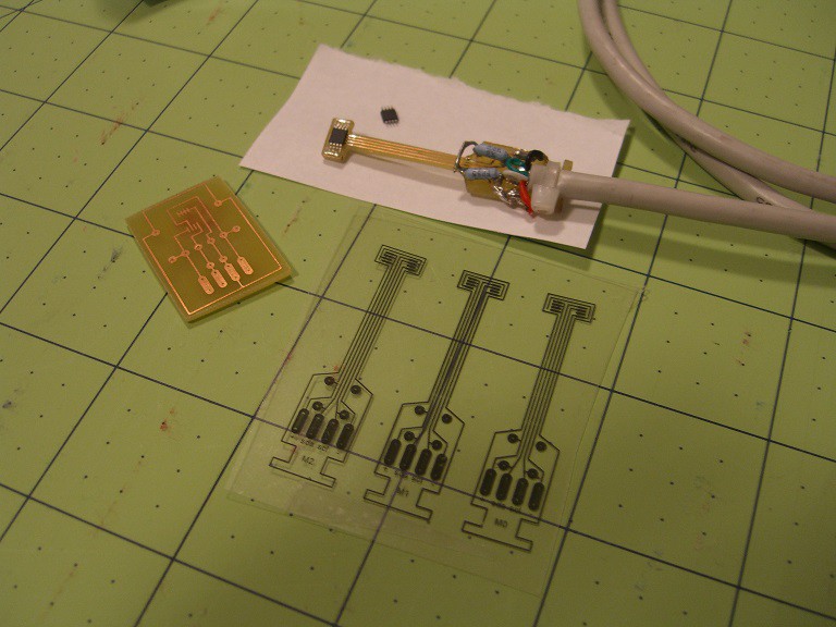
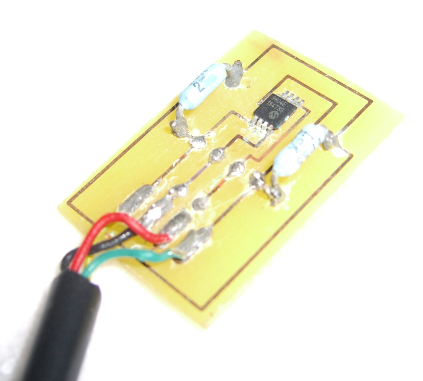
    The following picture shows some of the evolution of the temperature sensor pcb design. The rectangular pcb is the first design built. This circuit layout works well for testing, but doesn't look as cool as the guitar shaped design I came up with next. However the boring rectangular design works correctly. The second design has been a failure so far.

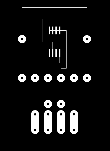
    The following is an AutoCAD drawing of the original pcb. Solder pads are provided for the two pull-up resistors, a decoupling capacitor and the temperature sensor itself.

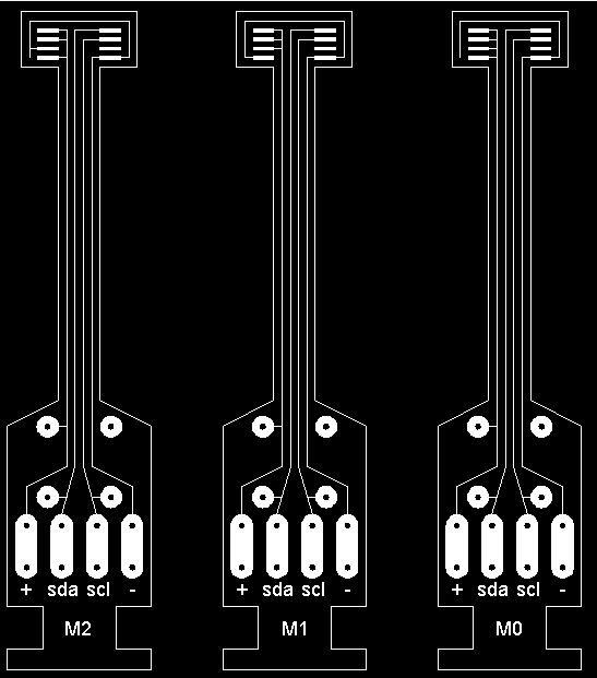
    Finally, this is the next revision of the temperature sensor circuit board. it allows the sensor itself to be placed into a tighter area. The differences in the three circuit boards establishes the i2c addresses. But after etching a set of these circuit boards, and assembling the circuit, I have not been able to establish communication with the sensor.

    Each of these will be wired in parallel.

  • howto i2c with Zipit

    Beaglebreath07/09/2014 at 07:49 0 comments

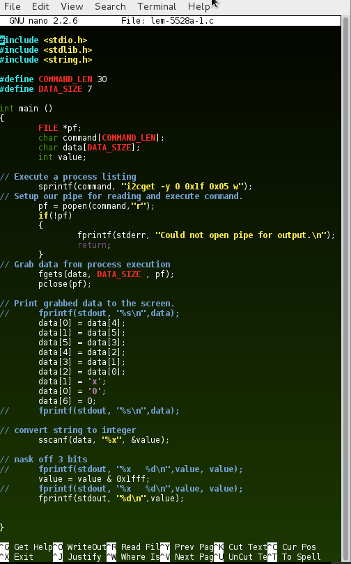
    The following code controls a Microchip Technology Inc.'s MCP9804 digital temperature sensor.

    The following was developed on a Zipit Z2 running openWRT.  The distribution includes the nano text editor and picoc c language compiler.  Some of the following code was blatantly cut and paste from other peoples web sites and from many many internet searches.  

    The first half of the code executes a user command and pipes the output of the command into an array of chars.  The user command that gets executed is:

    i2cget -y 0 0xlf 0x05 w

    • i2cget is a program which reads data from an i2c device
    • -y option disables user intervention
    • 0 designates which i2c bus to use for communication
    • 0xlf is the chip address of the temperature sensor
    • 0x05 is the memory address location of the temperature data
    • w specifies that a word length of data is to be retrieved.

    The second half of the code rearranges the order of the chars since they are received from the i2c sensor in a funny order.  After rearrangement, the array of chars is converted to an integer.  The most significant three bits are masked off.  The remaining integer can take a value from 0 to 8192 representing temperatures from -40 °C to 125 °C.

  • Zipit Z2 Docking Connector

    Beaglebreath07/08/2014 at 17:25 0 comments

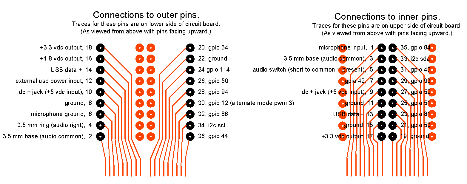
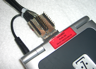
    On the rear of the Zipit Z2 is a 36 pin docking connector which gives you access to great things. The connector is a 36 pin which will connect to a Hirose ST40X-36S-CV(80). These are usually available from Digikey and Mouser. The connection provides:

    • DC power input ( 5 V dc and ground)
    • +3.3 Volt output
    • 1.8 Volt output
    • audio speaker output
    • audio microphone input
    • USB data + data - and power
    • i2c connections, sda, scl, power
    • and 16 gpio connections


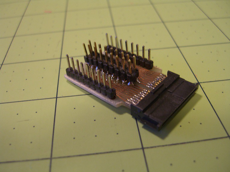
    The connector is the greatest thing in the world to solder when you have had too much coffee. I got frustrated with the tiny tiny wires on my cables breaking so I designed and built a breakout board to connect to the Zipit Z2.

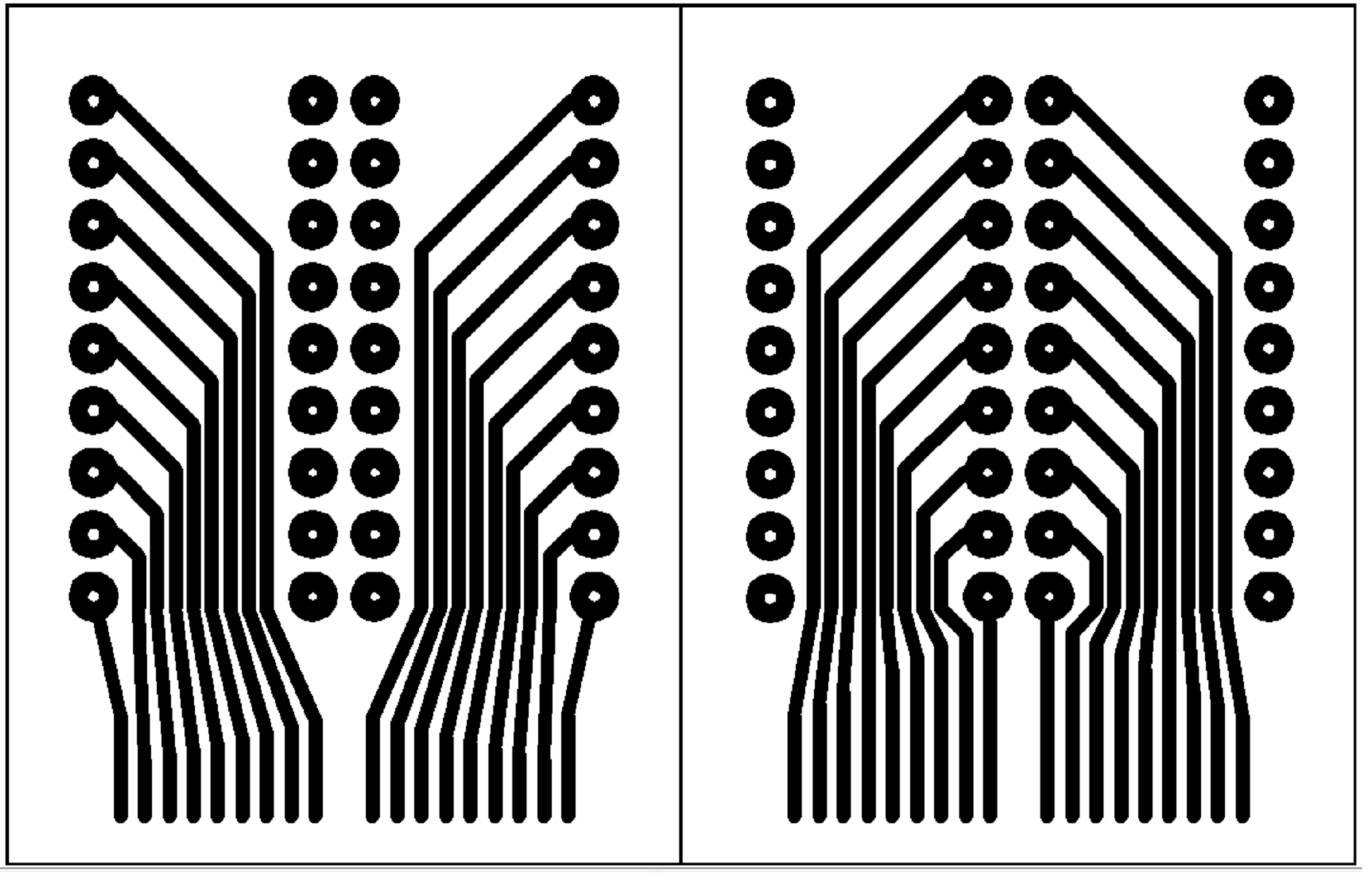
    This breakout board makes life much easier when experimenting with the Zipit.  The circuit board is a double sided board.  I drew the layout using AutoCAD and printed using 0.5 mm wide traces.  I ended up mass producing a bunch of boards at once, with the hopes that at least a few would survive my DIY etching process.

    Here is the pinout

    Here is the layout of the double sided circuit board.

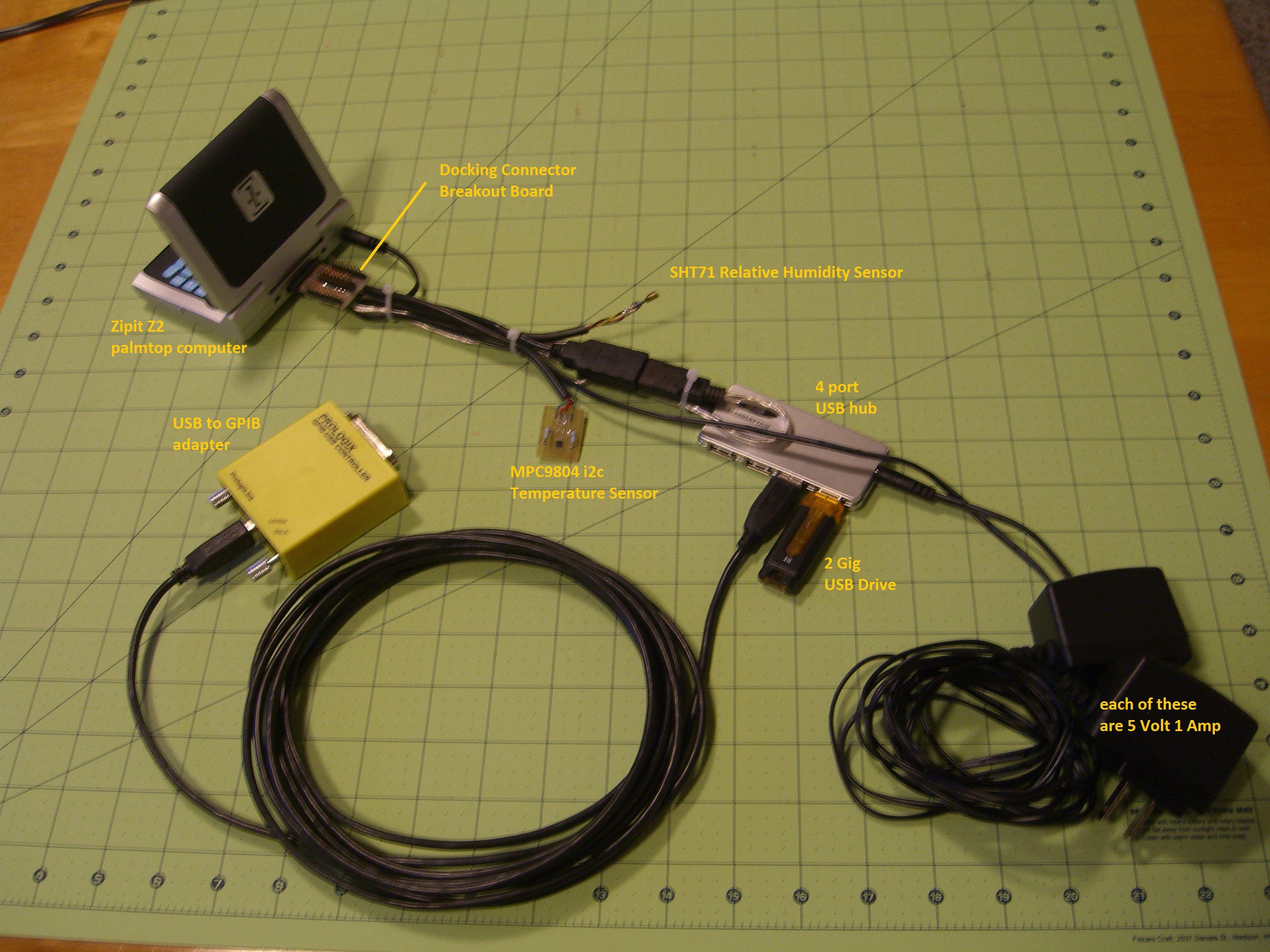
    The picture below shows off the docking connector with a USB cable soldered to the 0.1 inch header, as well as a 4 conductor cable for the i2c connections.

    The umbilical cord that is shown above is a god-awful mess.  I am going to redesign a connector board which will provide 4-pin connections to the the zipit for i2c sensors.  I will stack the circuit board of the USB hub on the new circuit board, and I will integrate the power supplies into a more compact solution.

    But at least this way I can get this project functional, until I am able to make it look pretty.

  • how the electronic stuff is connected

    Beaglebreath07/02/2014 at 08:47 0 comments

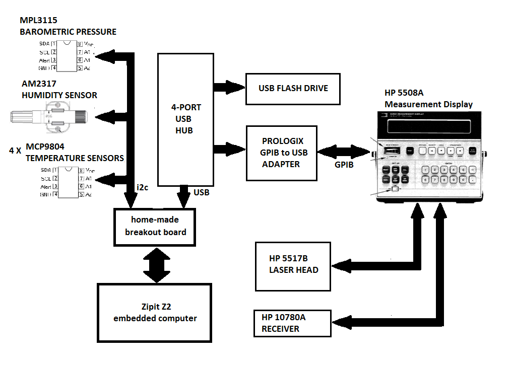
    Here is a picture of how everything will be connected

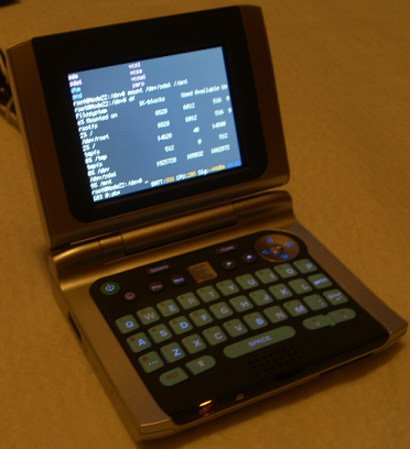
    The Zipit Z2 is a tiny clam shell computer.  It was originally designed to be an messenger device for tweens.  it is easy to reflash the internal memory with openWRT.  I have been using a distribution which was put together and compiled by slug_ on a #zipit irc channel.  The distribution was downloaded from here http://blog.engine12.com/?p=340  

    after installing configuring openWRT, I installed i2c_tools so that I can operate the environmental sensors.

    The Zipit will be used for the following purposes;

    • Controlling the i2c sensors
    • An HTML server will provide web page control of the interferometer system
    • Communicate with the HP 5508A measurement display
    • Provide a means to calibrate the sensors
    • Datalog sensor data and GPIB communication data.

    I made a breakout board for the docking connector of the Zipit Z2.  The docking connector is 50 pin connector with impossibly small 0.5 mm wide connections separated by the same distance.  I brought each of the connections out to 0.1 inch pins.  From these connections I wired four conductor cables to the i2c sensors and the USB hub.

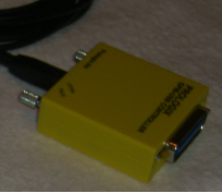
    I am easily able to communicate with the HP 5508A by using a Prologix USB to GPIB adapter.  The adapter uses a FTDI USB to serial chip which is automatically recognized by openWRT.  a file //dev/ttyUSB0 is automatically created.  I then simply echo and cat with the //dev/ttyUSB0 sending plain text GPIB commands and plain text responses.

    The i2c sensors include three MCP9804 temperature sensors which will be used to measure the temperature of the object being measured.  A fourth MCP9804 will measure the air temperature, while a AN2317 humidity sensor will be used along with a MPL3115 barometer will be used to measure the speed of light.

  • measuring thermal expansion

    Beaglebreath07/01/2014 at 17:12 0 comments

    Another significant source of error in length measurement is from the effect of temperature on the length of an object.  Materials have a physical property known as the Coefficient of Thermal Expansion. This property numerically describes the amount of length an object will change of a given change in temperature.

    The Coefficient of Thermal Expansion value can be programmed into the 5508A either from the

    • Manually typed in from the front keys on the 5508A
    • Programmed in from the GPIB interface on the 5508A

    The temperature of the object being measured is then input from either

    • Manually typed in from the front keys on the 5508A
    • Electronically input from sensors attached to dedicated rear connections
    • Programmed in from the GPIB interface on the 5508A

    The temperature input and the Coefficient of Thermal Expansion are then used in an equation to provide a measurement display of how long the measured object will be if it were at a standardized temperature of 20°C (or 68°F).  This consequently allows the operation of the interferometer at different temperatures.

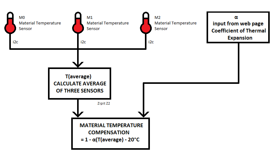
    The 5508A is originally intended to have up to three electronic sensors attached to the rear connections.The 5508A would then calculate the average of the three sensors.Apparently it is smart enough to know how many sensors are attached and takes the average value of the sensors.

    Optionally the average value can be typed in from the front key pad or the average value of some external sensors can be programmed through the GPIB port.For this project I will be using a Zipit Z2 embedded minicomputer to control a set of i2c temperature sensors.The sensors eventually will be built into V-Block clamps that will be used to hold the object being measured in a consistent manner.The temperature will hopefully represent the real temperature of the object being measured.The i2c temperature sensors values will be averaged by a compiled program in the Zipit Z2, just as the wavelength compensation was described in my previous post.The average temperature value will then be transmitted to the HP 5508A through a USB to GPIB adapter which will provide communications between Zipit Z2 and the HP 5508A.Finally an HTML server in the Zipit will provide a way for a user to input the Coefficient of thermal Expansion value.

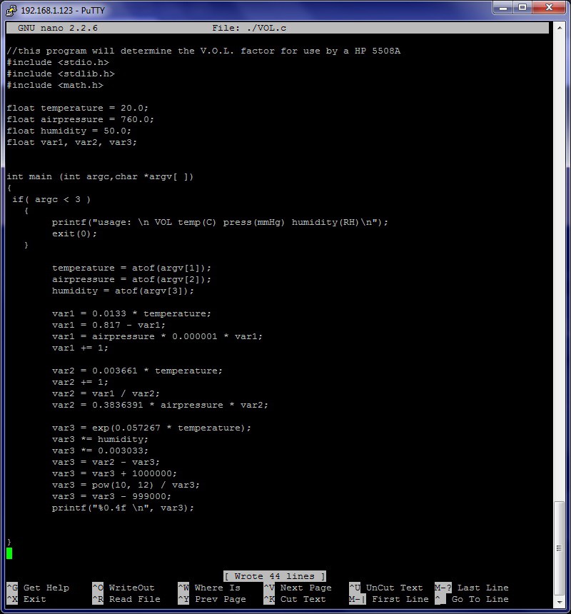
  • Edlen's equation in c

    Beaglebreath07/01/2014 at 07:10 0 comments

    I wrote the following program to follow the arithmetic worked out in Hewlett Packard Laser Measurement User's Guide Manual Part Number: 05528-90022 revision date March 1992 page 19-6.

View all 14 project logs

Enjoy this project?

Share

Discussions

Adam Fabio wrote 06/17/2014 at 04:30 point
Thanks for submitting your luminiferous aether detector to The Hackaday Prize, Beaglebreath! Sometimes you really, really want an accurate distance measurement - down to a wavelength or two of laser light! Keep the updates flowing - the more documentation you give us, the better your chance of measuring in SPACE!

  Are you sure? yes | no

Similar Projects

Does this project spark your interest?

Become a member to follow this project and never miss any updates