On the rear of the Zipit Z2 is a 36 pin docking connector which gives you access to great things. The connector is a 36 pin which will connect to a Hirose ST40X-36S-CV(80). These are usually available from Digikey and Mouser. The connection provides:
- DC power input ( 5 V dc and ground)
- +3.3 Volt output
- 1.8 Volt output
- audio speaker output
- audio microphone input
- USB data + data - and power
- i2c connections, sda, scl, power
- and 16 gpio connections
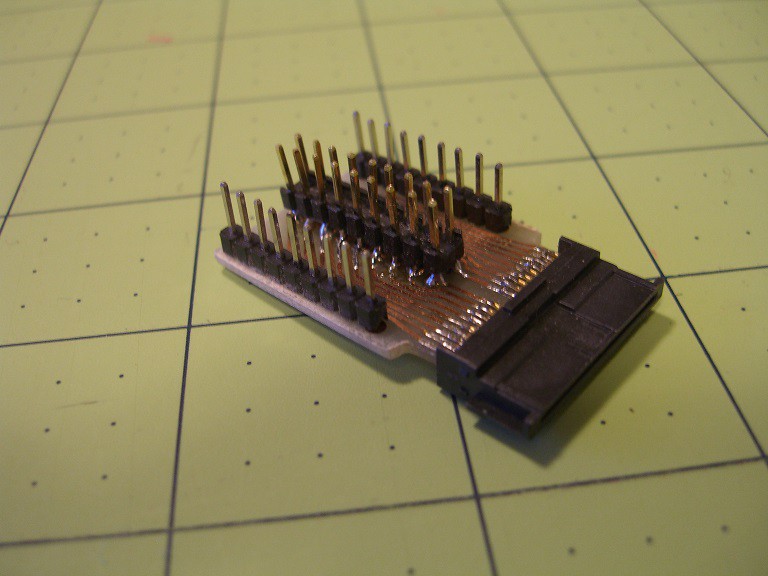
The connector is the greatest thing in the world to solder when you have had too much coffee. I got frustrated with the tiny tiny wires on my cables breaking so I designed and built a breakout board to connect to the Zipit Z2.

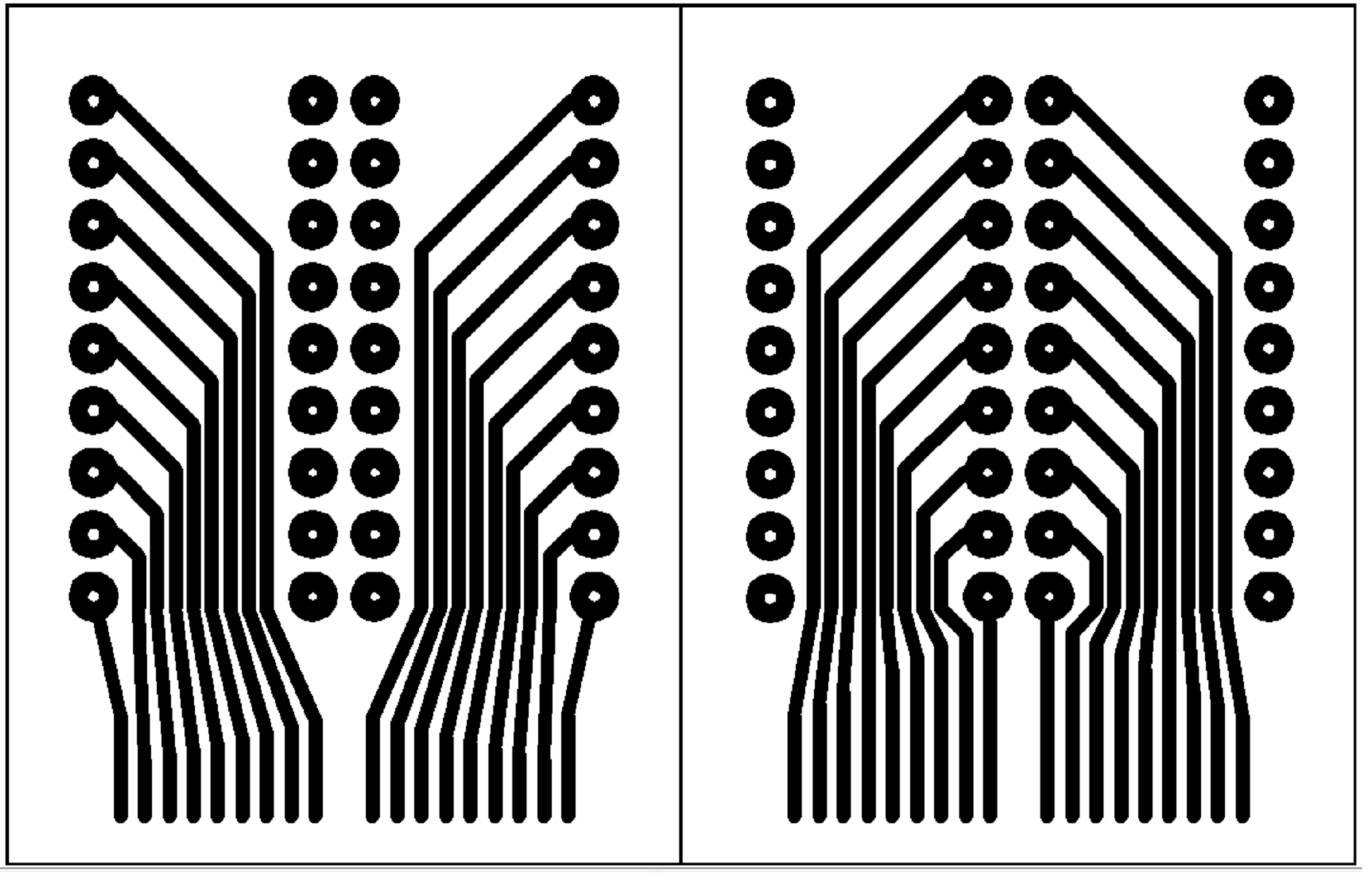
This breakout board makes life much easier when experimenting with the Zipit. The circuit board is a double sided board. I drew the layout using AutoCAD and printed using 0.5 mm wide traces. I ended up mass producing a bunch of boards at once, with the hopes that at least a few would survive my DIY etching process.
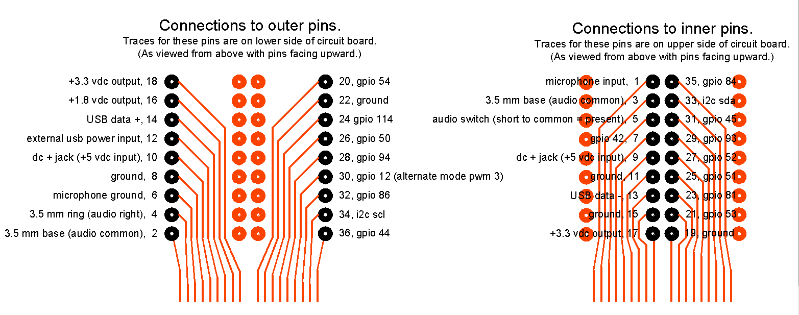
Here is the pinout

Here is the layout of the double sided circuit board.

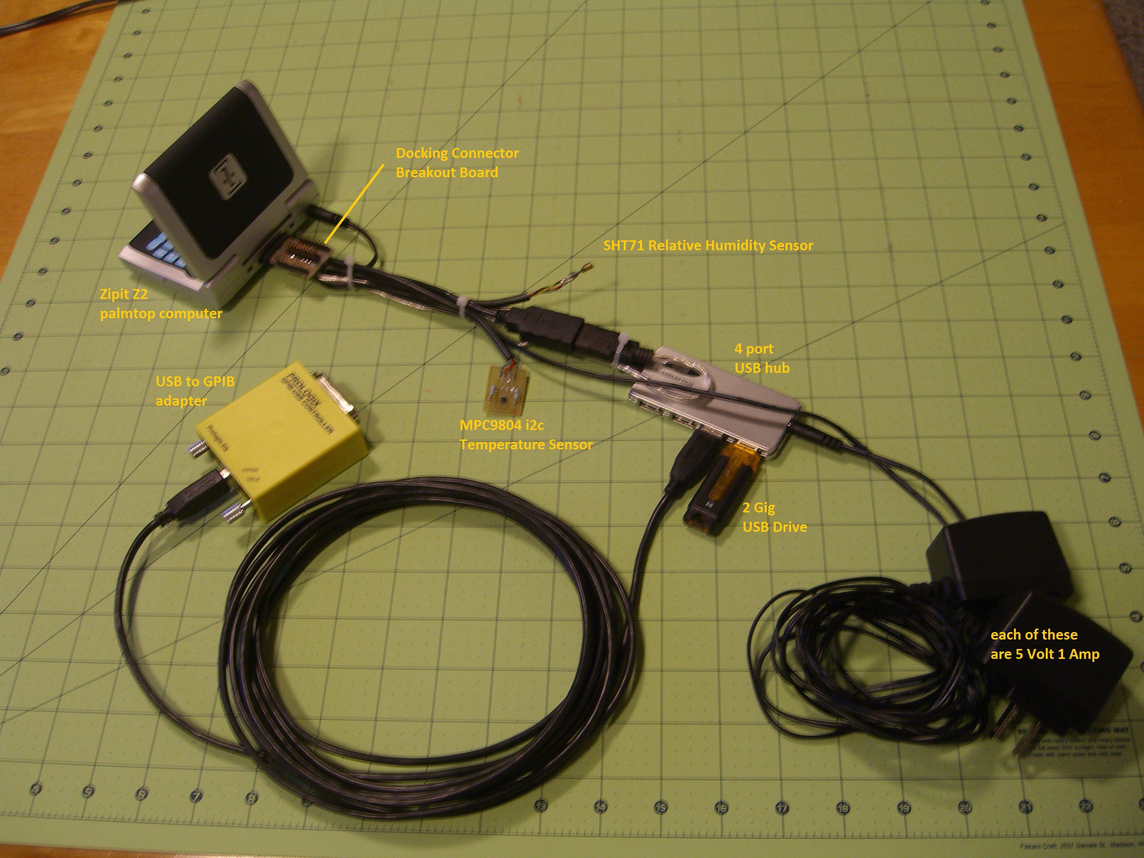
The picture below shows off the docking connector with a USB cable soldered to the 0.1 inch header, as well as a 4 conductor cable for the i2c connections.

The umbilical cord that is shown above is a god-awful mess. I am going to redesign a connector board which will provide 4-pin connections to the the zipit for i2c sensors. I will stack the circuit board of the USB hub on the new circuit board, and I will integrate the power supplies into a more compact solution.
But at least this way I can get this project functional, until I am able to make it look pretty.
 Beaglebreath
Discussions
Become a Hackaday.io Member
Create an account to leave a comment. Already have an account? Log In.