Kris Winer
-
Generation 2 hardware and upgraded firmware
06/01/2018 at 00:42 • 0 comments31 May 2018
Well, since the snippet about this project on the Hackday.com blog appeared I have received a lot of comments on the project, thank you all! I have also received the increased attention of AMS, and now have a lot more information about the use and status of the AS7265X system. In brief, the current board design, copied from the reference design in the data sheet (generation 1) is being changed to generation 2. The changes involve reassignment of the AS7262/3 slave reset pins and master AS72651 I2C bus pins. Furthermore, the changes are prompted partly because the I2C sector doesn't work in generation 1 with the current firmware. I2C in the AS7265X sensors is software based, so it depends on firmware alone (well, and the pin connections, of course). There is a new version of the firmware for generation 1 designs (like my current one) that is supposed to fix the I2C problem, but when I loaded it into my one assembled board I still couldn't get an I2C ACK from the AS72651 and AT mode works whether I2C_EN is HIGH or LOW.
So call the situation fluid.
This is understandable when bringing out a new chip set; bugs and typos are part of the package. And alpha users like me are both a blessing and a curse to companies like AMS. They benefit from having avid users point out early troubles and datasheet errors, etc, but the FAEs are busy and can't respond to every complaint. So far, AMS has been extremely generous with their time (thanks Frank!) and they have answered all of my questions as well as provided as much information as anyone could want. Kudos to AMS!
That said, this project is turning out to be quite a bit more challenging that the usual "copy-the-reference-schematic" design exercise.
I redesigned the board according to the generation 2 schematic and I have new generation 2 firmware ready to load when I get the boards back from OSH Park and assemble one of the boards. Maybe this time I will be able to get the I2C to work.
There are also going to be significant revisions in the data sheet with several I2C and AT commands deprecated and many more added. In particular, there will be registers for both raw data and calibrated data. Apparently, what I have been reading from my limited usage of the photospectrometer is the raw data. I am not sure yet what sort of calibration is involved here; the calibration coefficients, which are readable via I2C and UART, range from 1 to 17, so these are likely multipliers. But I don't know yet. More questions for AMS.
Bottom line, one step forward, two steps back, I need to get the photospectrometer working properly before I can explore any real world applications.
-
Normalized spectra...
05/28/2018 at 19:01 • 3 comments28 May 2018
Like a kid with a new toy, I could not resist testing the spectrometer out on various targets.
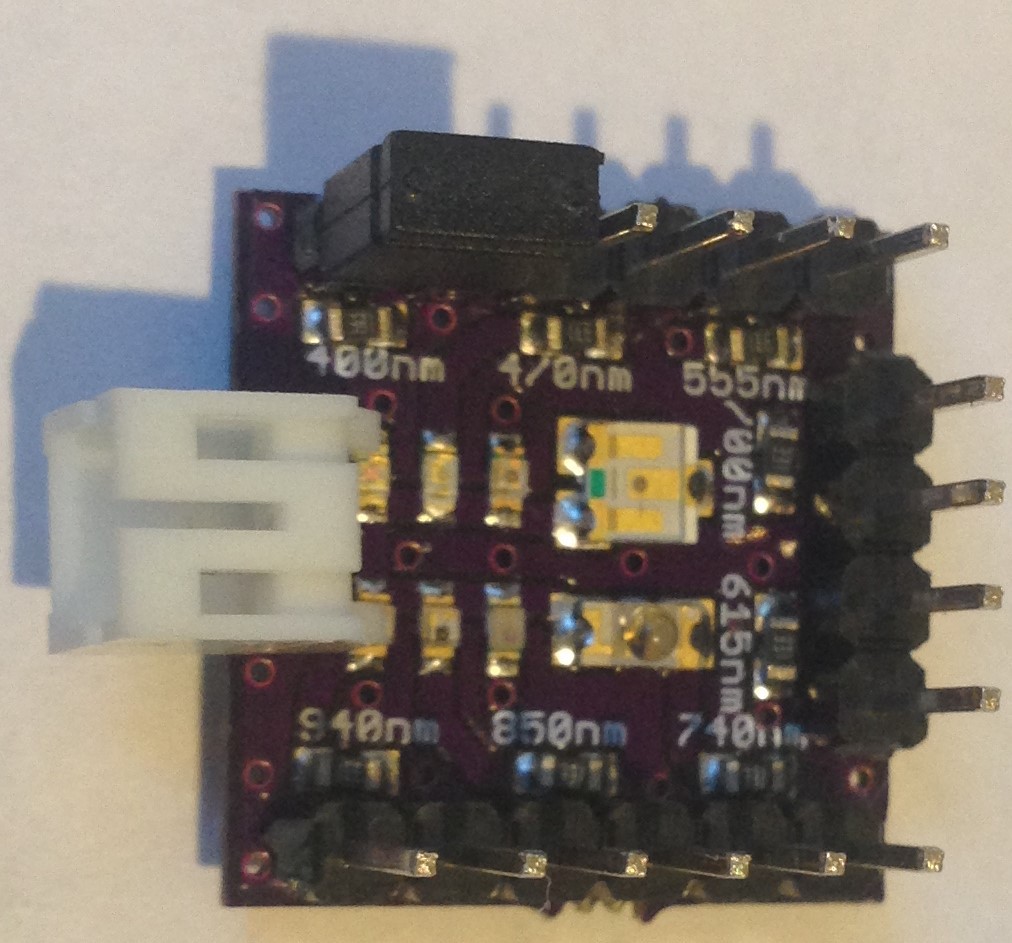
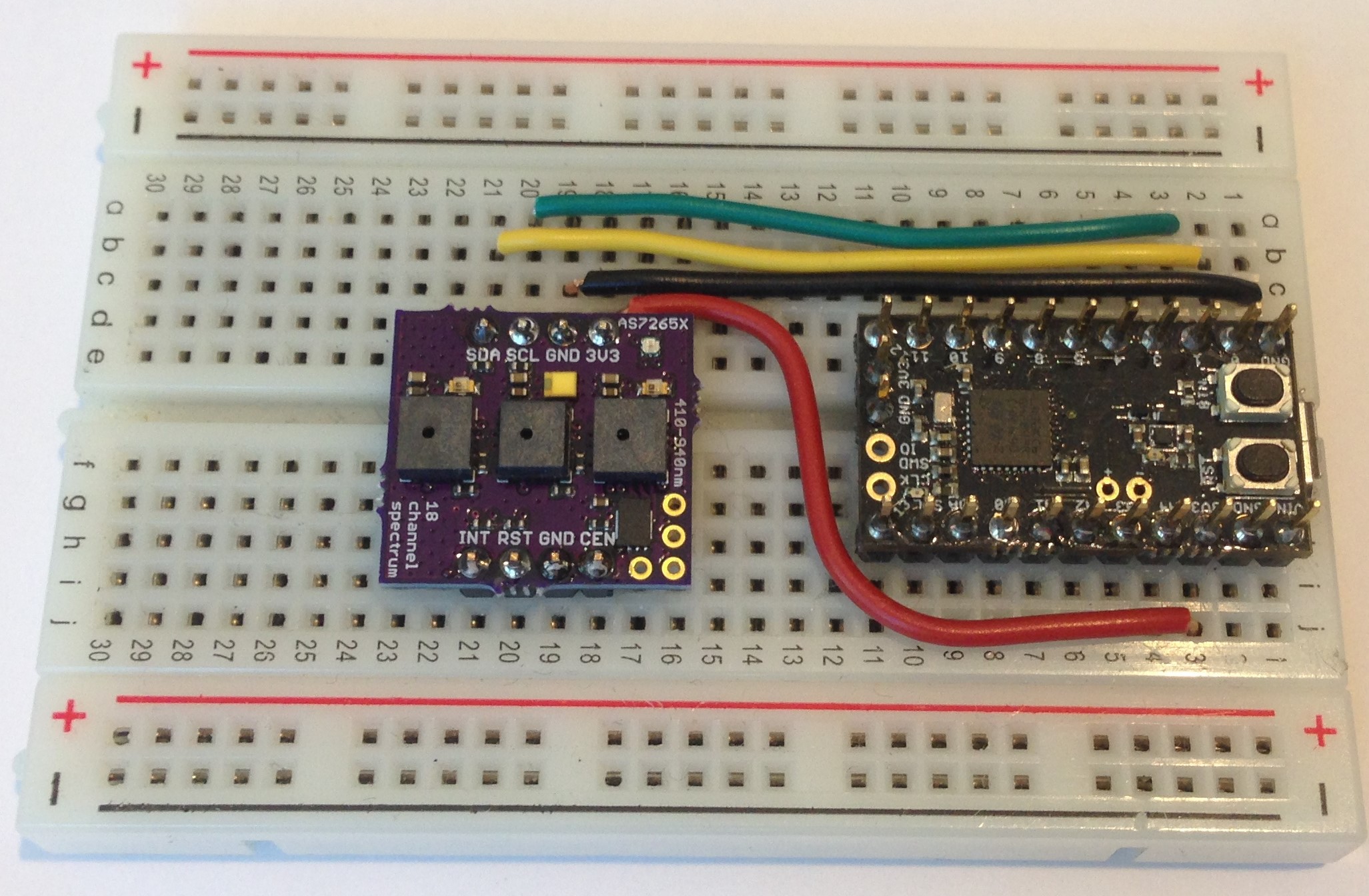
First, I soldered headers onto the board and mounted it on a breadboard along with a small Arduino-programmable (Ladybug) STM32L432 MCU:
![]()
I tested out the led controls a bit more and found that by default the top and bottom source leds are off. So I played around with turning them on and testing whether the spectrometer could "see" them. I think the 850 nm leds I bought simply do not work. I have never gotten a signal from the 850 nm when the led was supposed to be on. The 940 nm led does work and I experimented with different current drives up to 50 mA. My MCU board has a 150 mA LDO so I don't want to press things too much. The broad band (5700 K, 90 CRI) led (yellow square thing on the AS7265X board) defaults to 100 mA as far as I can tell. I must say, the AT commands are somewhat cryptic and I will have to do a lot more experimenting to make sure I understand how to use the led sources correctly. It would help if I could actually see the leds!
I programmed the button to turn on the broad-band source, then take a spectrum, then turn off the broad-band source, kind of like flash photography. It sort of kind of works, but there are latency issues due to the relatively slow serial interface and I don't always get a clean 18-channel spectrum. Sometimes the leading or lagging channel is missing or mixed up with OKs and other AT command activity. But it is usable, and I can simply position the breadboard over an object, press the button like taking a picture, and read off the 18-channel data from the serial monitor. Still a bit clunky but eminently usable.
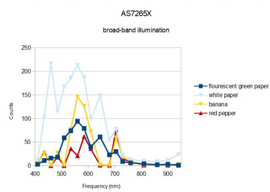
I did a little more measuring with this rig held a few centimeters from each object:![]() The white paper spectrum is again basically the spectrum of the broad-band source (plus the 940 nm led I think). When applied to various household objects, the absorption of the objects changes the spectrum recorded by the spectrometer. So flourescent green paper absorbs strongly in the blue but not much elsewhere. The banana and red pepper absorb strongly in the blue and between ~600 and 700 nm. Definitely different and distinguishable.
The white paper spectrum is again basically the spectrum of the broad-band source (plus the 940 nm led I think). When applied to various household objects, the absorption of the objects changes the spectrum recorded by the spectrometer. So flourescent green paper absorbs strongly in the blue but not much elsewhere. The banana and red pepper absorb strongly in the blue and between ~600 and 700 nm. Definitely different and distinguishable.
I think the right way to plot such data is by correcting for dark current and normalizing by the white paper spectrum. We basically want to know how much of the source light is reflected back, and it makes sense to plot the reflected spectra of our test object as a ratio to the reflected spectra from a quasi-ideal (white paper) reflecting object. The dark current is zero, at least that is what I measure with the broad-band illumination off at these gain (2) and integraton time (100 ms) settings.![]() I have color coded the spectra to approximate the colors of the objects (clever, no?). What we see is that florescent green paper reflects light uniformly from ~500 to ~800 nm; it is the absence of blue and the presence of light from ~650- 700 nm that accounts for the flourescent green apparently. The banana and red pepper both have a similar spectrum with double peaks at ~600 nm and ~750 nm, what we see is determined mostly by the first portion of the spectrum. The banana has nearly equal parts of green (560 nm), yellow (585 nm) and orange (610 nm) components so looks yellow to us, while the red pepper is mostly yellow (585 nm) and orange (610 nm). The peaks at 705 - 730 nm nm dominate in both spectra (typical human visible light sensitivity is 390 - 700 nm) and accounts for the dominant red color of the pepper.
I have color coded the spectra to approximate the colors of the objects (clever, no?). What we see is that florescent green paper reflects light uniformly from ~500 to ~800 nm; it is the absence of blue and the presence of light from ~650- 700 nm that accounts for the flourescent green apparently. The banana and red pepper both have a similar spectrum with double peaks at ~600 nm and ~750 nm, what we see is determined mostly by the first portion of the spectrum. The banana has nearly equal parts of green (560 nm), yellow (585 nm) and orange (610 nm) components so looks yellow to us, while the red pepper is mostly yellow (585 nm) and orange (610 nm). The peaks at 705 - 730 nm nm dominate in both spectra (typical human visible light sensitivity is 390 - 700 nm) and accounts for the dominant red color of the pepper.
Of course, human perception of color intensity varies as well. I am not trying to rigorously analyze these results or claim we can "predict" the color of objects by this kind of spectroscopy alone. I just claim that the results are plausible. In other words, the spectrometer seems to be working.
We can draw a couple of conclusions from this limited application of the AS7265X spectrometer. Firstly, it can and does work as an integrated 18-channel spectrometer without special optics or inordinate fuss. Secondly, it can distinguish between objects of different color. I will admit that now that I have 18 channels, I want more. The difference in color between a banana and red pepper is really due to the difference in a few channels (in particular, 555 nm and 705 nm). So for visible colorimetry this might not be the best choice of sensor since almost half the 18 channels are outside of the normal visible range.
But the promise of this spectrometer (apart from being a hoot to use) is to identify unknown materials. Can it really do this? I will be looking into this next... -
First spectrum results
05/28/2018 at 06:42 • 0 comments27 May 2018
I received the pcbs with the corrected design yesterday and put one of the boards together today. Assembly was straightforward, much like the first time, since the board layout didn't really change much. The 850 and 940 nm leds got smaller and I properly connected the AS72651 sync pin (AKA ADO) to the AS72652 reset pin, according to the data sheet schematic, which apparently in this instance is correct.
I loaded the firmware onto the 4 Mbit SPI flash (version 1.2.7, still the same as the one on the AMS download site), power cycled the spectrometer and was happy to see the rgb led blink once and go out, as it should.
I am still having trouble getting the device to respond to I2C commands and it is basically unusable in I2C mode. I have asked AMS if there might be a reason for this, and I will figure this out eventually. I2C mode is nice since each of the 18 channels can be queried individually and I2C is a more natural way (at least for me) to interface the spectrometer with a microcontroller.
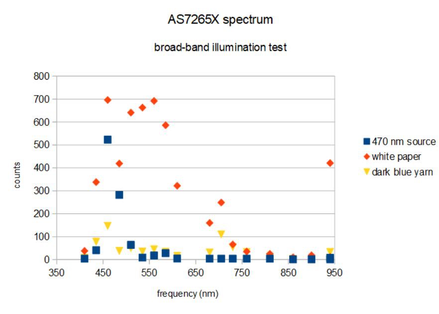
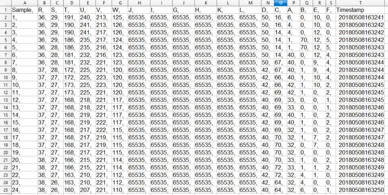
I was able to get the spectrometer to work in UART mode using the AT commands. This is useful to check for basic function; I was able to to verify that all three sensors are functional. It is convenient to have a single command (ATDATA) that returns all 18 of the data channels, although the ordering of the data is not straightforward. There is another command (ATXYZR) which is supposed to output the counts in order of wavelength but I found this not to be the case using the calibration plate as a reference. But ATDATA does seem reliable, so I did a little bit of testing just to see what the new spectrometer could do.
![]()
Using the bright 470 nm led on the calibration plate I measured a strong signal peaking at 460 nm with a strong side band at 485 nm, just as I should. I turned on the broad-band 5700 K 90 CRI source on the spectrometer board for the next two measurements. First, I pointed the spectrometer at white paper, and see a spectrum characteristic of the luxeon Z ES led output with a narrow peak at ~450 nm and a broad peak at ~600 nm. In other words, white paper reflects most of the source light without strongly absorbing any particular wavelength so the reflected spectrum looks like the emitted spectrum. There is the odd exception of the peak at 940 nm, which could have been my finger in the field of view. (I will have to be more careful when I start using the spectrometer in earnest!)
Next I turned the spectrometer with the same 5700 K 90 CRI source on to a knitted cap I use as a bowl on my work bench. The material is made of dark blue yarn with coarse knitting, so it absorbs a lot of the light due to its rather porous nature and absorbs mostly in the red reflecting weakly in the blue, in this case at ~460 nm with a little bit of a bump in the green at 560 nm and maybe one at 705 nm.
I think best results using the spectrometer will be had with the spectrometer mounted inside some sort of container (like a toilet paper tube) to limit stray light and to allow the spectrometer to be placed over objects to be measured.
I also found it tiresome to constantly enter ATDATA into the serial monitor whenever I wanted to record a spectrum so I will likely program the button on my Dragonfly development board to take a spectrum measurement on pressing. This will be very convenient.
Lot's more testing to do yet. I need to create some kind of fixture to allow more reliable testing instead of holding things in my hands. I want to develop some more automated way to plot the spectra. I need to understand how to optimize gain and integration times, etc.
I also want to find out if the broad band source is sufficient to distinguish between different materials (with less extreme differences than white paper and dark blue yarn!) such as salt and sugar, for example. I'd also like to sort out the I2C interface on this device.
But overall, I am happy with progress to date. I now have a small, inexpensive spectrometer whose utility I can start to assess.
-
First Test of Calibration Plate
05/14/2018 at 03:19 • 2 commentsMay 13, 2018
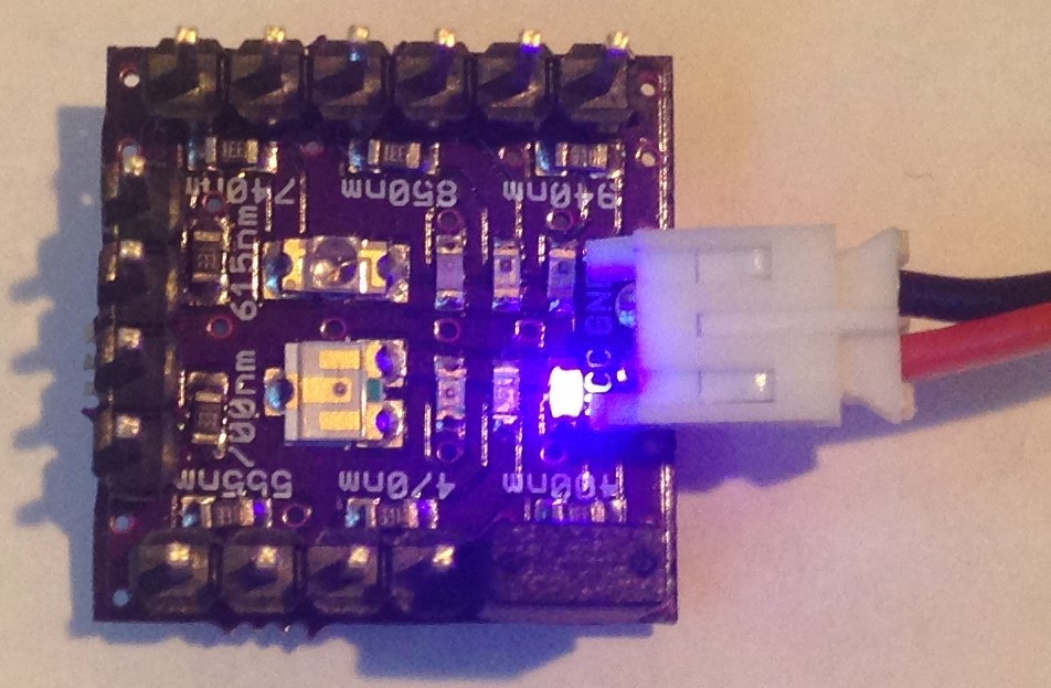
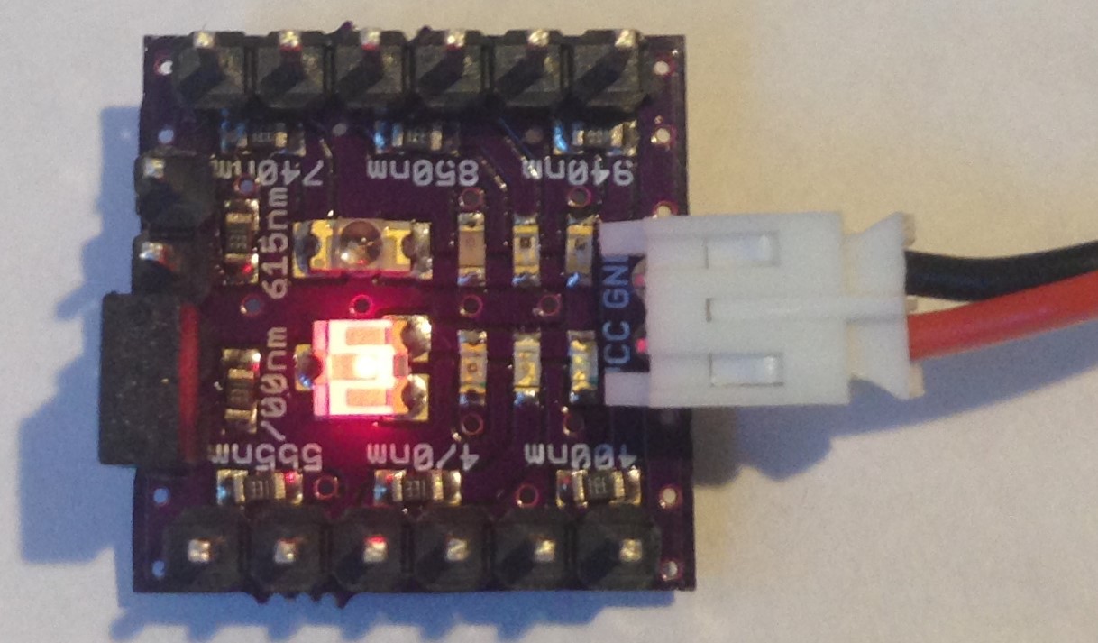
I received the calibration plate pcbs on Friday and put one of them together. I could see visually the light from the 400 nm, 470 nm, 555 nm, 615 nm and 700 nm leds; the 740 nm, 850 nm, and 940 nm are invisible to the human eye. I had 333 and 100 ohm 0603 resistors sitting around so I chose to use 330 ohm resistors for current limiting for all eight of the leds. The 400 nm, 470 nm, and 615 nm leds were quite bright (to my eye) while the 555 nm led was not; next time I will use a 100 ohm resistor for it. I am using ~4 V from a LiPo battery as the power source and jumper pins to choose which of the leds to enable like this:
![]()
Here the 400 nm led would be on if the battery was installed.
Unfortunately, after I solderd the headers on to the board the 615 nm led became quite faint; obviously somehow the soldering affected it but I don't know how.
Also, my preliminary tests with the DemoBoard spectrometer lead me to believe that both the 740 nm and 850 nm leds are simply not working. Again, I don't know why. So surprisingly, making a calibration plate with eight narrow-band led sources turned out to be harder than it would seem. I have two more pcbs so I will try again.
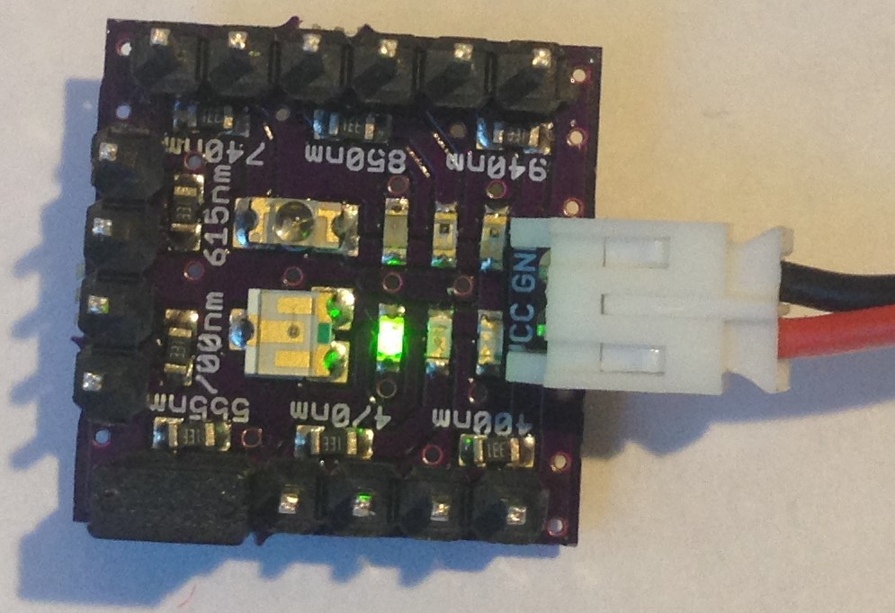
Here is another "problem" with the leds that do work. They seem to output different amounts of light. Now, I don't require that the radiant fluence be identical for the kind of tests I have in mind, just that the light is bright enough that the spectrometer can get a strong enough signal to register the light. Here is what four of the visible leds look like:
![]()
400 nm
![]()
555 nm
![]()
615 nm
![]()
715 nm
The 615 nm is particularly disappointing since this would have been a great test of the AS72651 sensor, but it is so faint here that it just doesn't register at all.
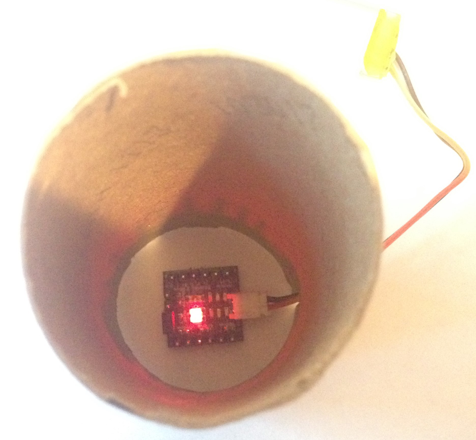
I created a sophisticated measuring apparatus using a Mark 1 toilet paper roll at the bottom of which I placed the calibration plate and placed the DemoBoard on the top approximately 130 mm away. The toilet paper roll provides some isolation from external light sources and a fixed distance between sensors and sources but no way to manage alignment. The latter attribute is fine, since one of the questions I want to answer is what kind of results can be expected from just using the 3-chip solution as a single (hand-held) spectrometer.
![]()
DemoBoard sits on top with sensors looking down.
This is a question raised in the comments. The gist of the concern is that the 18-channel spectrometer is really composed of three spatially-separated six channel spectrometers and that obtaining sensible results might require special care in alignment of the sensors or a very large sample size or even additional optical elements. My hope was to simply show that, at least at the separation and diameter of a toilet paper role, I could record eight signals from a small area source without any special alignment or other kind of fussing.
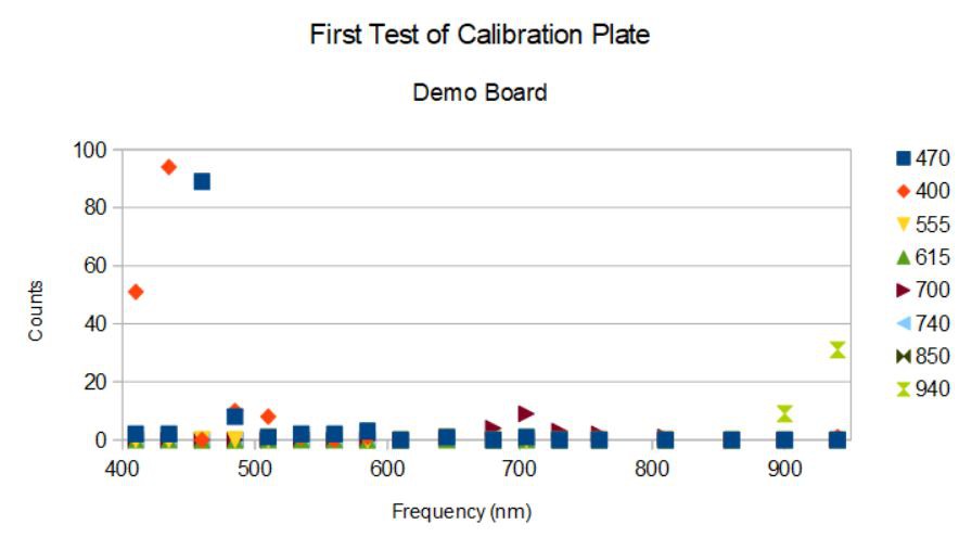
While the flaws of the calibration plate make this first test non-definitive, I would say there are a few things to learn still. Here is the spectra I recorded from eight single samples with one each of the eight leds enabled using the default AS7265X DemoBoard conditions (165 ms integration time, gain setting = 2):
![]()
I see four peaks, one at 435 nm for the 400 nm source led, one at 460 nm for the 470 nm source led, one at 705 nm for the 700 nm source led, and one at 940 nm for the 940 nm led. The intensities (counts) are rather low. Disappointingly, I see nothing from the 555 nm nor 615 nm leds even though I can see their light. And it looks like the 740 nm and 850 nm leds are simply not functioning.
The good news is that of the four "peaks" I do measure, half come from the AS72652 and half come from the AS72653. So lack of alignment doesn't prevent light to be registered on these two spatially-separated sensors from a small source. It almost seems like the AS72651 is not working, or that the 740 and 850 nm leds are not working or both.
I want to repeat this test with at least the 555 nm led limited by a 100 ohm resistor and I hope that another try fixes the 615 nm led, which was glowing brightly before I soldered on the headers. I also want to repeat it using my own sensor board once I am sure I have the design right (I expect to hear back from AMS this week with answers to my several questions about the reference design). So, much more testing to be done just to answer the basic question "will the spectrometer even work as intended"!
-
Initial Sketch Construction
05/10/2018 at 02:59 • 0 commentsMay 9, 2018
I am spending my time waiting for the next pcb revision to come back from the fab trying to make the best use of the one board I assembled. Although flawed, I am using it to learn about this sensor suite. I also heard back from ASM; they are very busy but promise an answer to my questions next week. This is progress, since if I can keep their attention I might get answers to the multitude of questions my initial efforts at building this spectrometer have generated.
I cannot get the I2C devices to acknowledge on my device and I don't know if this is normal and to be expected, or is a consequence of the circuit error(s) on the current design. I developed an AS7265X class and tried a simple read of the hardware version and device type registers and got nothing. I also made an attempt to use the same sketch on the Demo Board. At least in this case, I can see the two devices AS72652/AS72653 on the master I2C bus but when I connect to the AS72651 slave bus that is supposed to talk to the MCU I again see no I2C devices. Well, the DemoBoard is by default set in the UART mode so I would have to remove a resistor and add a resistor to place the board into I2C mode. I will just wait for my next revision rather than start Bubba-ing the Demo board.
I did get somewhere using the UART interface and the AT command set using my board. I connected RX/TX to SDA/SCL and then pulled I2CEN LOW to enter UART mode. I wrote a little program to use the AT command set to query hardware and software versions, set the integration time and gain of the sensors, and to query the number of devices present (sadly, there are only two, the AS72652 doesn't seem to be connected properly or is malfunctioning, see last log entry). Here is the output:
![]()
When I power on and the MCU runs the program I curiously get info that I didn't ask for. The first command is supposed to be AT which should return an OK. It does so if I press reset and open the serial monitor, but when I power off and then power on I get this curious notice that there is a 4 MB SPI flash (correct) and the AS7265 device is indicated along with the software version 1.2.7. Maybe this is the default message on power on.... Then the hardware version is 403Cx, the software version again 1.2.7 and the number of devices somehow gets lost (it is 2, meaning AS72651 and AS72653). Thereafter the device responds normally, showing the default gain and integration times as well as my successful changes of the same except for those of the AS72652 which responds to no commands. The integration time is set in units of 2.8 ms, so that 36 (max 255) corresponds to ~100 ms. Lastly, I ask for the temperatures of the three ICs in Centigrade. Presumably 100 is due to the AS72652 being out of reach but 44 C is pretty warm for the AS72651.
Well, in any case, I succeeded in getting some useful information from my device via the UART interface and I will post this sketch as the first installment of my AS7265X github repository.
-
Successfully Loaded Firmware, First Test of Design
05/09/2018 at 01:29 • 0 commentsMay 8, 2018
It took me quite a while to figure out how to get the firmware loaded onto the SPI flash. The easy part was dragging and dropping the binary firmware file I downloaded from the AMS download site onto the QSPI flash of one of my Dragonfly development boards. The QSPI flash can be chosen in the Arduino IDE to emulate a disk drive on Windows machines (maybe others as well) so I just dragged and dropped and then the firmware was on the Dragonfly QSPI flash. Easy peasy!
I wrote a little program to attach the QSPI flash as a DOSFS (FS.h) object but could not get the file to open. All of the other firmware files (for the EM7180) showed as FW type with the .fw extension and these would open just fine, but not the binary type file with the .bin extension or any other extension I tried. I tried opening the files with Notepad and Wordpad, saving as generic files, and then loading these onto the QSPI flash. While this allowed opening the files with DOSFS the files were corrupted and no valid firmware was actually written to the 512 kByte SPI flash on the AS7265X board. Finally, I opened the firmware with ProXoft's BinaryViewer, selected the entire contents, and saved this to a generic file and, lo and behold, I got a FW type file with a .fw extension that I was able to open with DOSFS. By comparing the bytes read back from the 512 kByte flash and the bytes read with the BinaryViewer I convinced myself that the firmware was written to the flash correctly.* Whew!
The AS72651/2/3 will blink their indicator leds when they have no firmware or incorrect firmware (the rgb led proved to be a useful diagnostic) or when they are not soldered properly (or in reset mode for the same reason) as I also found out. Before the firmware was flashed, all three of the leds were blinking resulting in a rainbow of colors. Once the firmware was finally successfully flashed, I saw a red led momentarily flicker on power up and then just a green led flashing twice a second. The red led is the AS72651 successfully downloading the firmware from the SPI flash. The green led, it turned out, was the AS72653 in some distress. I think there was a cold joint on the nRST pin since I didn't see any solder at that location. I just reheated the board, tapped on the AS72653 with my tweezers and tried again. This time, just the initial red light and then nothing...just what I was hoping for!
I then scanned for I2C devices but saw nothing. Now the AS7265X devices aren't true I2C devices in that they have a virtual I2C interface. I am not sure what this means but I decided to try the UART interface instead of spending hours writing a program to read and write to the virtual registers and verify function. I will do this eventually anyway, but I was anxious to know if my board was alive or not.
I connected a 3V3 FTDI connector to the board using the FTDI's 3V3 and GND for power. I had to use a jumper to connect the I2C enable to GND to get the board into UART mode. All of this worked well (despite the 4K7 pullups on the I2C/UART bus) and I was able to get the right COM port in the AMS-supplied GUI and verify that 1) firmware version 1.2.7 was indeed loaded onto the flash and made its way into the AS72651, 2) the broad band led produced a blinding white light at the 12.5 mA setting (but I couldn't see the 850 or 940 nm light from the other two illumination leds to tell if they are working), and 3) the AS72651 and AS72653 smart spectral sensors are working! I was able to take data which varied as I moved the sensor around. Unfortunately, The AS72652 showed 0XFFFF for all six channels and does not seem to be working. Here is what the data I took looks like:
![]()
R-W channels are in the IR, A - F are in the blue and, unfortunately, I am missing G - K in the green/red.
Now the reference design is a curious thing, and there are some typos I am sure. (I am still waiting for AMS to respond to my few questions about the schematic, but so far, crickets...) One of which is the fact that the schematic shows AS72652 RST connected to AS72651 ADO. Huh? There is zero mention of this in the data sheet, the DemoBoard user guide, or the Hardware Design Application Note. Is it a typo, or is it necessary for getting proper performance from the AS72652? Well, I assumed the former in this design, but I am beginning to think the latter is correct. And, in fact, I finally checked the DemoBoard with a voltmeter and verified that AS72652 RST is not connected to the AS72651/3 RST pins as I had assumed for this design (silly me!) but is directly connected to AS72651 ADO! OK then. This must be correct!
So I redesigned the board to connect AS72651 ADO (pin 13) to AS72652 RST (pin 2) and I replaced the ADO PTH previously exposed on the board edge with another GND next to the I2C enable. This way, I can more easily jumper I2C_EN to GND for UART mode, which has so far turned out to be pretty darn useful with AMS's GUI.
I will start writing an Arduino sketch using I2C now that I have a partially functioning board and I am waiting for OSH park to fab the next revision. Overall, I am pleased with the progress and I hope that this can be the final revision for a fully functioning spectrometer. I doubt even in this case it will be the last, since I haven't tested the illumination leds (frequency, intensity, placement effects) nor put the calibration plate to work nor gotten a real sense of using the spectrometer, so future revisions are still likely. But I would at least like to start with a device functioning as intended. I think I am getting close....
*I wrote the bytes, maybe not every single last one of them but, yeah, basically, I wrote them...
-
First Assembly of the Spectrometer
05/08/2018 at 01:15 • 0 commentsMay 7, 2018
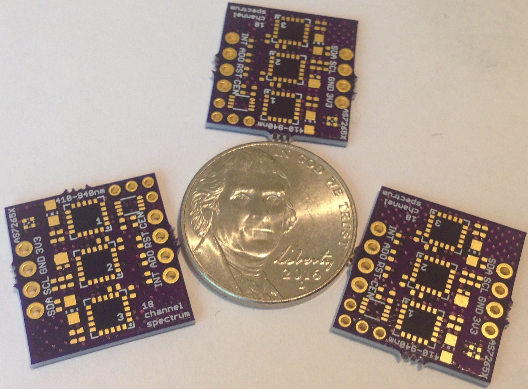
I received the AS7265X sensors today by FedEx and spent the day putting together the first board.
![]()
The assembly was uneventful and I was able to verify I could read the SPI flash ID and read and write to the flash using an external STM32L476 MCU development board. This dev board has an on-board QSPI flash memory so that I was easily able to drag and drop the firmware I got from AMS onto the QSPI flash. I hit a snag in that the DOSFS file handler I usually use to read files on the QSPI flash wouldn't open the AMS firmware file. Not sure why yet.
I think the sensors are soldered properly because while I was trying to load the firmware the rgb led I added to the board for indication was blinking once a second like it should be while the AS72651 is trying to load its firmware from the SPI flash. I think the I2C bus won't work until there is firmware in the SPI flash for the AS72651 to read which I hope explains why I could get no ACK from the S72651 when scanning the I2C bus for devices.
Once I get the firmware loaded onto the flash I will be able to do more testing...
-
Firmware in hand...
05/05/2018 at 00:10 • 1 commentMay 4, 2018
I finally succeeded in getting a reply to my many email inquiries to AMS by addressing my request to the corporate offices in Austria. The very nice Nicole arranged access to the AS7265X firmware for me (a special account is required) and put me in touch with the AS7265X engineer Frank who graciously agreed to try to answer my technical questions about their reference circuit and device operations, etc. Fat city!
As soon as I receive the 3-chip set I ordered from AMS I will be able to assemble and start testing the spectrometer. Woohoo!
I watched the mobile tricorder demo on you tube one more time and noticed they are depending on a MEMS FPI (micro-electromechanical Fabry-Perot interferometer) for spectral information beyond the spectral range of the AS7265X (410 - 940 nm) into the mid IR (1300 - 2000 nm or further). The purpose of using this frequency range is for identification of carbon compounds; this begs the question whether the glucose/sucrose discrimination that seems like magic in the video is possible with just the AS7265X alone. I guess I will find out soon enough.
AMS doesn't seem to have any such MEMS FPI device but Hamamatsu does. The very nice and compact C14272 is such a FP interferometer with < 15 nm resolution from 1350 - 1650 nm. It would make a very nice addition to my $25 Spectrometer, so I asked Hamamatsu about ordering some, but the price is so high even for 100 quantity that my $25 spectrometer would end up being more like a $250 spectrometer! So at least for the first iteration, 410 - 940 nm will have to do...
-
Parts ordered, pcb in hand...
05/04/2018 at 00:10 • 0 comments05/04/2018
I have not been able to find the 3-chip set anywhere for sale at the usual retail outlets. The best I could do was find a supply of AS72652 at Arrow for $7+ each, and a projected delivery of mid-May for all three sensors at www.futureelectronics.com at $4.88 each but with a minumum order of 500! I thought I would check the AMS website just one more time and lucky for me, I was able to place an order for 10 each of the AS72651/2/3 for $4.50 each plus $39.50 shipping. This was an unexpected but pleasant surprise.
Still no lead on a source for the requisite firmware. I left a phone message at the AMS US office and sent another e-mail request this time to the corporate office in Austria but I am not expecting any replies. The AMS strategy seems to be to slowly make the needed elements of their smart sensor solution available to the public as production supply ramps up. And this is fine by me, just a bit frustrating since I also just received my updated pcbs from OSH Park and I am ready to put a couple together.
![]()
My fallback for the firmware is to solder some leads to the Adesto flash on my AS7265X DemoBoard and just read the ~56 kByte firmware file onto my laptop, and then load my own flash with it. I'd prefer a source from AMS as well as an application note on how to use it, etc but I guess beggars can't be choosers!
I am not sure how long it will take to get the sensors from AMS, but I hope by next week I will be able to assemble and load the firmware onto the first boards and then see how well they work using the led illumination I have chosen (broadband + 850 nm + 940 nm). Pretty exciting now...
-
Spectrometer Calibration Plate
04/28/2018 at 23:43 • 0 commentsApril 28, 2018
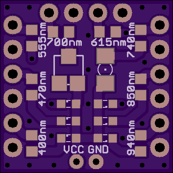
I thought it would be nice to have a small device that could emit one or more narrow bands of light in the detection range of the AS7265X spectrometer, so I decided to design a simple calibration plate:
![]()
There are eight discrete narrow-band leds on the board matching within 10 nm the peaks of the spectral sensitivities of eight of the eighteen channels available in the AS7265X and spanning the full 410 - 940 nm range of the spectrometer. The board is designed to be powered by a small 3.7 V LiPo battery. Each led is turned on by connecting the appropriate current limiting resistor to ground by shunting using a simple jumper between two machine pin headers. This way one or all of the leds can be enabled just by adding or removing the shunting jumpers.
The plate could also be used on a breadboard by connecting the resistors to current sinking circuitry, etc. Perhaps this would be useful for an automated process.
I tried to limit the package sizes to 0603 but there is a gap between about ~650 nm in the red to 850 nm in the near IR where no 0603 leds could be found, so I am using one 1206 led for 740 nm and one 1212 led for 700 nm. The 850 nm and 940 nm leds in the 0603 package are new; I chose to use the 0805 package size in the spectrometer I just designed a couple of weeks ago since these were not yet available.
My plan is to simply use this board to check that all three of the spectrometers in the three-chip set are functioning and perhaps get some idea of how the spectrometer behaves with different sources of light. But reflection spectroscopy is different from emission spectroscopy, so I don't know how useful this calibration plate will end up being for testing.
The other obvious use though would be to use this calibration plate as the illumination source for reflection spectroscopy since a good measurement of the light reflected from a bright white background could be useful as a reference for identifying absorbance "lines" in unknown materials.
Compact, $25 spectrometer
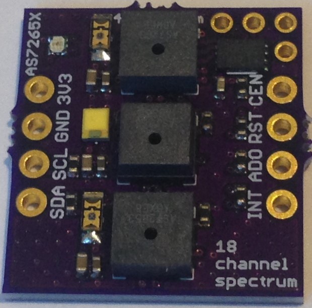
AMS's new AS7265X 3-chip set promises a compact, 18-channel, 20 nm FWMH spectrometer for less than $25
 The white paper spectrum is again basically the spectrum of the broad-band source (plus the 940 nm led I think). When applied to various household objects, the absorption of the objects changes the spectrum recorded by the spectrometer. So flourescent green paper absorbs strongly in the blue but not much elsewhere. The banana and red pepper absorb strongly in the blue and between ~600 and 700 nm. Definitely different and distinguishable.
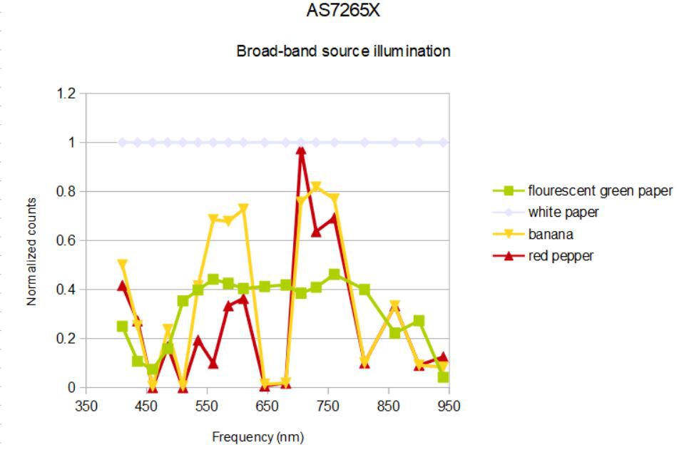 I have color coded the spectra to approximate the colors of the objects (clever, no?). What we see is that florescent green paper reflects light uniformly from ~500 to ~800 nm; it is the absence of blue and the presence of light from ~650- 700 nm that accounts for the flourescent green apparently. The banana and red pepper both have a similar spectrum with double peaks at ~600 nm and ~750 nm, what we see is determined mostly by the first portion of the spectrum. The banana has nearly equal parts of green (560 nm), yellow (585 nm) and orange (610 nm) components so looks yellow to us, while the red pepper is mostly yellow (585 nm) and orange (610 nm). The peaks at 705 - 730 nm nm dominate in both spectra (typical human visible light sensitivity is 390 - 700 nm) and accounts for the dominant red color of the pepper.