 Kris Winer
-
More thoughts on DemoBoard and pcb redesign
04/23/2018 at 19:43 • 0 commentsApril 23, 2018
I didn't appreciate it at first but the UART interface via FTDI connector that is the default with the DemoBoard allows the sensor to work without an MCU. The AS7265X sensor set is configurable by the AMS-supplied GUI with which the data can be captured and stored for later plotting. This is a pretty convenient way to use the spectrometer.
I intend to use an MCU and set the I2C interface as default on my spectrometer design. But I should be able to also make it work with the FTDI connector by simply connecting the I2C enable (CEN on the board) to GND and using SDA/SCL as UART RX/TX. We'll see if the pullups get in the way.
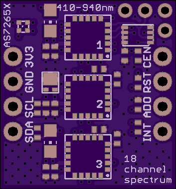
One thing I learned from the DemoBoard is that exposing the SPI port to load the required firmware onto the SPI flash is needed. There is some discussion in the AS7265X data sheet of loading firmware directly via I2C to the AS7265X. I think this is for the case where there is no SPI flash and the firmware needs to be loaded to the sensor from the host. But I don't know. I was hoping I could load the SPI flash with firmware by this method, and I might still be able to. But I decided to redesign the pcb to add the SPI port just in case this doesn't work.
![]()
I still haven't gotten an answer to my queries from AMS. I might just have to copy the firmware from the SPI flash on the demoboard. The AS7265X chip set won't become available for purchase until mid-May which should be just around the time I get these boards back from OSH Park. So I hope to have a working design by then...
-
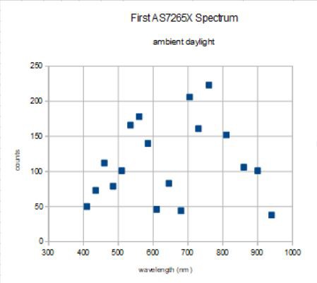
First AS7265X Spectrum
04/21/2018 at 22:49 • 2 comments04/21/2018
I received the AMS DemoBoard yesterday and started playing with it. Curiously, it has a device marked AS7263 where I expected the AS72651 to be. Maybe these are the same device. They both have the same spectral response, but maybe only the AS72651 has the extra I2C master engine in it. Don't know. I have asked AMS in an e-mail.
![]()
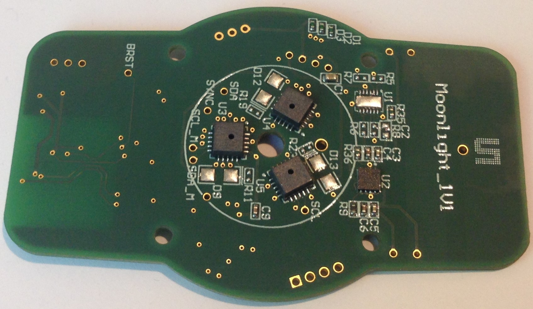
There is a flex connector to interface with the 4 MBit Adesto flash, which has the firmware, not very useful for firmware copying, which is maybe the point. No firmware came with the extensive documentation on the included USB thumb drive.
You can see the big solder pads for adding source leds. The tri-foil arrangements of the sensors is pretty nice; this means all three sensors will see the reflected light emitted from the object. This will be hard to replicate on the small board I chose so it might be worth increasing the board size just for this arrangement, which seems ideal.
After I realized I needed to use the USB cable that came in the kit to connect to the board (the cable has a built in FTDI connector) I was able to quickly and intuitively gather my first data. I took a continuous set of ~25 samples, saved the data to a file and imported the data into an open office spreadsheet. I couldn't figure out how to plot it easily so I just hand-typed in one of the sample sets versus the bin wavelength:
![]() This was with the three sensors pointed at the window looking outside in bright sunlight. The peak at ~550 nm makes sense since the dominant color is bright green reflected off of the sun-lit oak trees. But the largest intensity is at ~760 nm, deep in the red. There is one of those digikey red rulers in the field of view. I also made no attempt to correct for dark current, etc. Just wanted to see 1) if the three sensors worked and 2) what kind of data I could expect. So far so good. Now I just need to buy the three sensor ICs, obtain and load the firmware, and I should be able to get my board to do the same.
This was with the three sensors pointed at the window looking outside in bright sunlight. The peak at ~550 nm makes sense since the dominant color is bright green reflected off of the sun-lit oak trees. But the largest intensity is at ~760 nm, deep in the red. There is one of those digikey red rulers in the field of view. I also made no attempt to correct for dark current, etc. Just wanted to see 1) if the three sensors worked and 2) what kind of data I could expect. So far so good. Now I just need to buy the three sensor ICs, obtain and load the firmware, and I should be able to get my board to do the same.
Compact, $25 spectrometer
AMS's new AS7265X 3-chip set promises a compact, 18-channel, 20 nm FWMH spectrometer for less than $25
 This was with the three sensors pointed at the window looking outside in bright sunlight. The peak at ~550 nm makes sense since the dominant color is bright green reflected off of the sun-lit oak trees. But the largest intensity is at ~760 nm, deep in the red. There is one of those digikey red rulers in the field of view. I also made no attempt to correct for dark current, etc. Just wanted to see 1) if the three sensors worked and 2) what kind of data I could expect. So far so good. Now I just need to buy the three sensor ICs, obtain and load the firmware, and I should be able to get my board to do the same.