 igorfonseca83
-
1Tools and Materials
The following tools and materials were used for this project:
Tools:
- 3D printer - The whole body of the robot is 3D printed. Several hours of 3d printing were needed for building the whole structure;
- PLA filament - White and black PLA filaments where used for printing the body;
- Screw driver - Most of the parts are connected using bolts;
- Super glue - Some of the parts were attached using super glue;
- Pliers and cutters
- Solder iron and wire
Electronics:
- Arduino Uno (link / link) - It's used as the main controller of the robot. It sends signals to the motors and communicates with the WiFi module;
- ESP8266-01 (link / link)- It's used as a 'WiFi modem'. It receives signals from the control interface to be performed by the Arduino Uno;
- SG90 servomotors (x6) (link / link) - Four servos were used for the arms, and two for head movements;
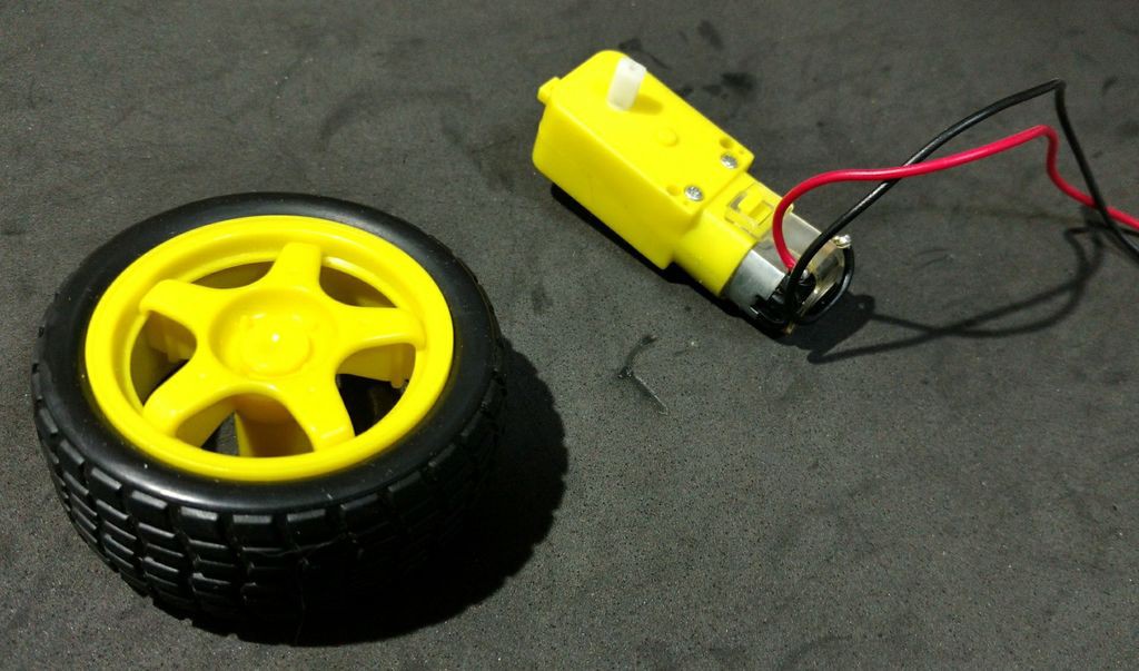
- DC motors with reduction and rubber wheels (x2) (link / link) - They allow the robot to travel small distances;
- L298N dual channel H-bridge (x1) (link / link) - It converts Arduino digital outputs into power voltages to the motors;
- 16 channels servo controller (link / link) - With this board one can control several servomotors using only two Arduino outputs;
- MAX7219 8x8 LED display (x4) (link / link) - They are used as the face of the robot;
- Micro USB cable - Used for uploading the code;
- Female-female jumper wires (some);
- Male-female jumper wires (some);
- Smartphone - A Motorola 4.3" Moto E smartphone was used. Others with similar size might work as well;
- 18650 battery (x2) (link) - They were used to power the Arduino and other peripherals;
- 18650 battery holder (x1) (link / link) - They hold the batteries in place;
- 1N4001 diodes (x2)
- 10 kohm resistores (x3)
- 20mm on/off switch (x1)
- Protoshield (link) - It helps wiring up the circuit.
Mechanics:
- Ball wheels (x2)
- M2x6mm bolts (+-70)
- M2x10mm bolts (+-20)
- M2x1.5mm nuts (x10)
- M3x40mm bolts (x4)
- M3x1.5mm nuts (x4)
The links above are a suggestion of where you can find the items used in this tutorial and support the development of this project. Feel free to search for them elsewhere and buy at your favorite local or online store.
Did you know you can buy the Anet A8 for only $155.99 at Gearbest? Get yours: http://bit.ly/2kqVOdO
-
23D Printing
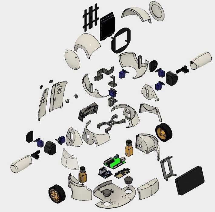
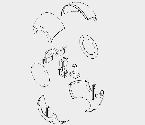
The robot structure was entirely produced with 3D printing using Autodesk Fusion 360. In order to enable the production of robot replicas in makerspaces or fab labs, where the maximum time of use of the printers is crucial, the design of the robot was divided in pieces smaller than three hours of printing each. The set of parts is glued or bolted for body mounting.
The model is composed of 36 different parts. Most of them was printed without supports, with 10% infill.
- Head top (right/left)
- Head bottom (right/left)
- Head side caps (right/left)
- Face back plate
- Face front plate
- Neck axis 1
- Neck axis 2
- Neck axis 3
- Neck center
- Arm (right/left)
- Shoulder (right/left)
- Shoulder cup (right/left)
- Shoulder cap (right/left)
- Arm axis (right/left)
- Bust (rigth/left)
- Chest (right/left/front)
- Wheels (right/left)
- Base
- Phone holder
- Back (right/left)
- Knobs (right/left)
- Locker (right/left)
The procedure for mouting the robot is described on the following steps.
You can download all the stl files on the following websites:
- https://www.thingiverse.com/thing:2765192
- https://pinshape.com/items/42221-3d-printed-joy-robot-robo-da-alegria
- https://www.youmagine.com/designs/joy-robot-robo-da-alegria
- https://cults3d.com/en/3d-model/gadget/joy-robot-robo-da-alegria
- https://www.myminifactory.com/object/55782
This is a experimental prototype. Some of the parts need some improvements (for later updates of the project). There are some known issues:
- Interference between the wiring of some servos and the shoulder;
- Friction between the head and the bust;
- Friction between the wheels and the structure;
- The hole for some screws is too tight, and need to be enlarged with a drilling bit or a hobby knife.
If you don't have a 3D printer, here are some things you can do:
- Ask a friend to print it for you;
- Find a hacker/maker space nearby. The model was divided in several parts, so that each parts individually takes less than four hours to print. Some hacker/maker spaces will only charge your for the materials used;
- Buy your own 3D printer. You can find an Anet A8 for only $155.99 at Gearbest. Get yours: http://bit.ly/2kqVOdO
- Interested in purchasing a DIY Kit? If enough people are interested, I might be offering a DIY kits on Tindie.com. If you would like one, send me a message.
![]()
-
3Overview on the Circuits
![]()
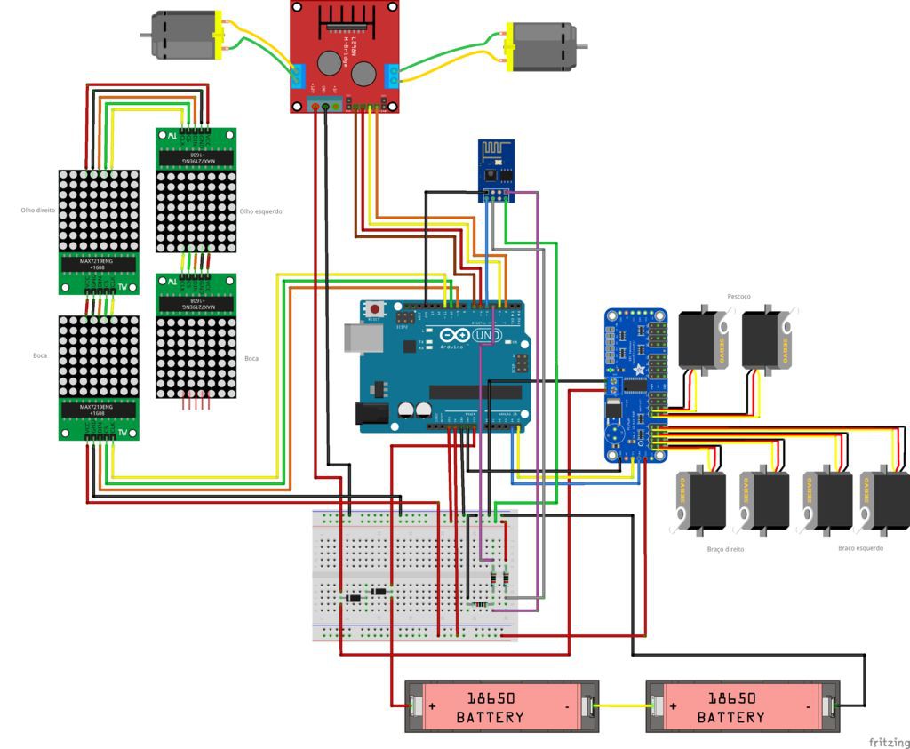
The robot is controlled using an Arduino Uno at it's core. The Arduino interfaces an ESP8266-01 module, which is used to remote control the robot over an Wi-Fi network.
An 16-channel servo controller is connected to the Arduino using I2C communication and controls 6 servomotors (two for the neck and two for each arm). An array of five 8x8 LED matrices is powered and controlled by the Arduino. Four Arduino's digital outputs are used for the control of two DC motors, using an h-bridge.
The circuits are powered using two USB power banks: one for the motors and one for the Arduino. I've tryed to power the whole robot using a signle power pack. But ESP8266 used to lost connection due to spikes when DC motors turned on/off.
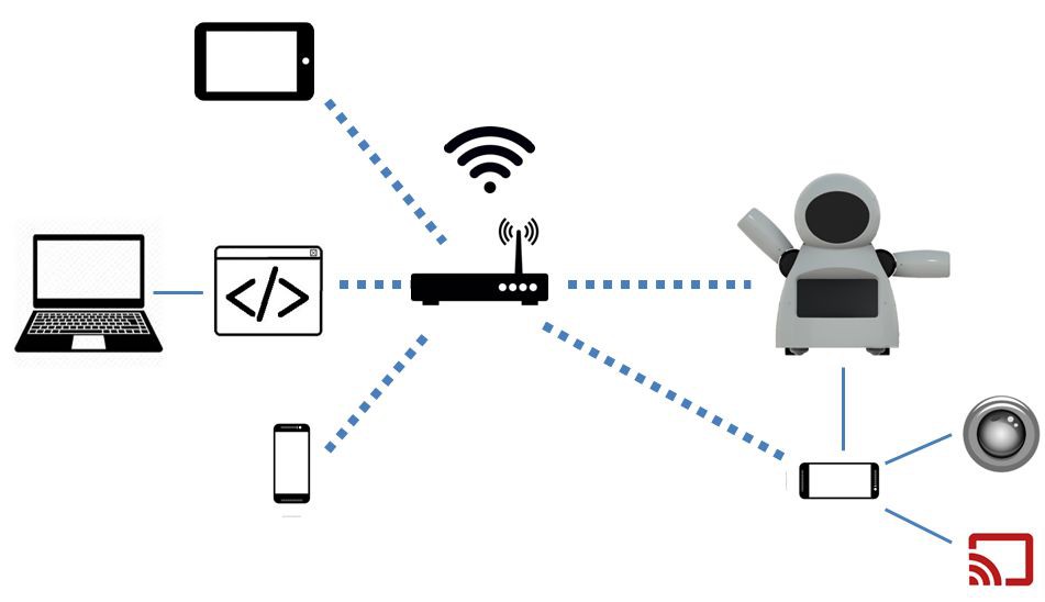
The chest of the robot has a smartphone. It's used to broadcast video and audio to/from the control interface, hosted on an ordinary computer. It can also send commands to the ESP6288, thus controlling the body of the robot itself.
One might notice that the components used here might not be optimised for its purpose. A NodeMCU might be used instead of the Arduino + ESP8266 combination, for instance. A Rapsberry Pi with a camera would replace the smartphone and controll the motors as well. It's even possible to use an Android smartphone as the "brain" for your robot. That's true... An Arduino Uno was choosed because it's very accessible and easy to use for everyone. By the time we started this project, ESP and Raspberry Pi board where still relatively expensive in the place we live... once we wanted to build and inexpensive robot, Arduino boards where the best choise at that moment.
![]()
-
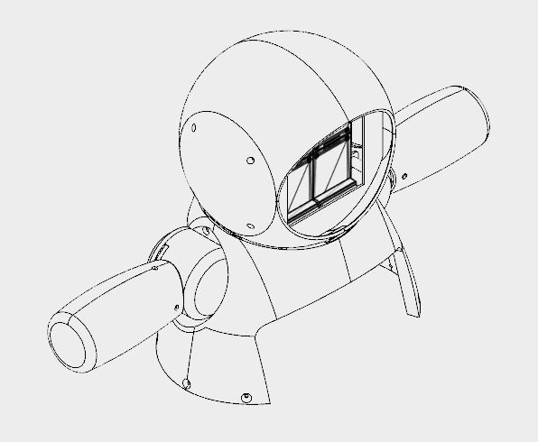
4Assembling the Face
![]()
![]()
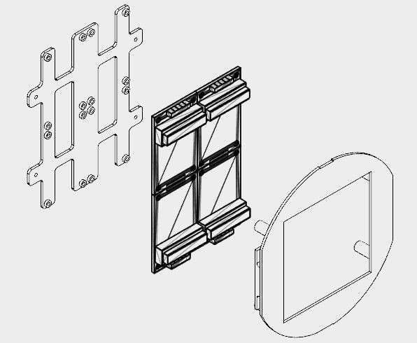
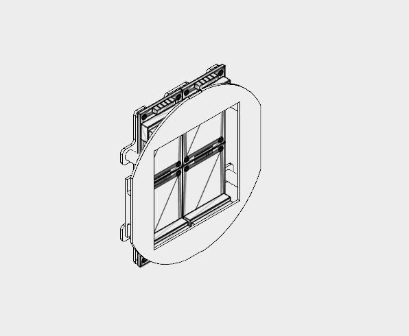
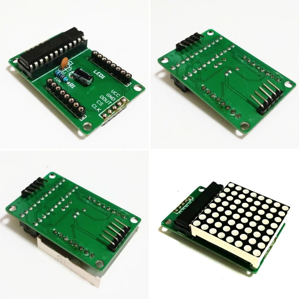
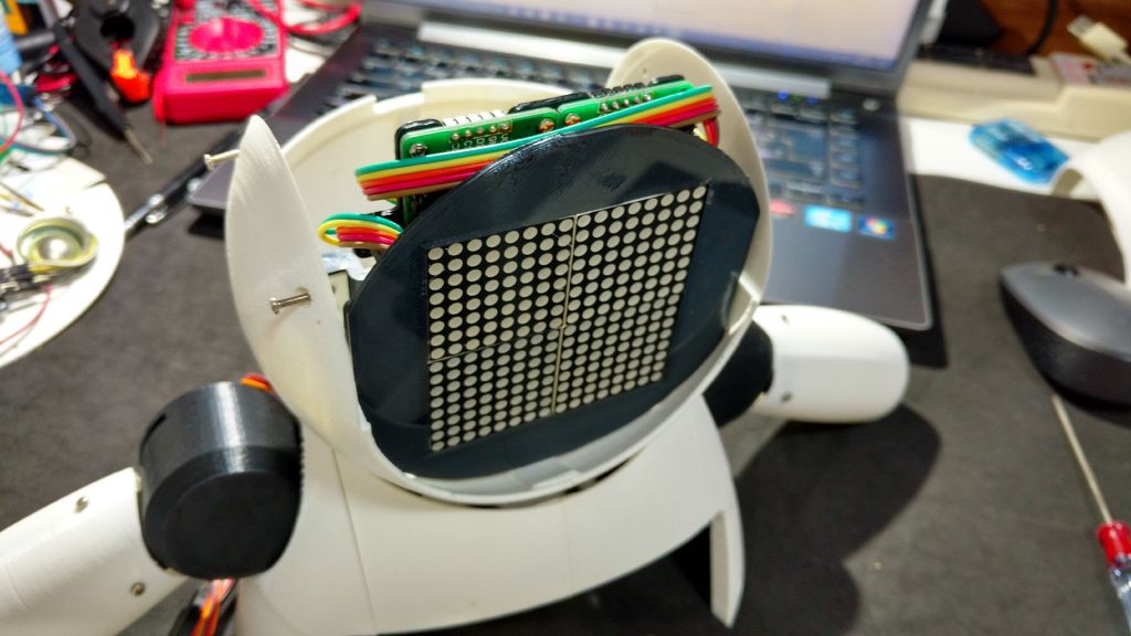
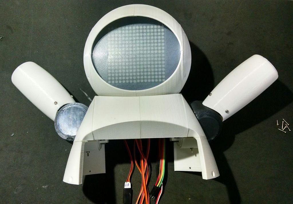
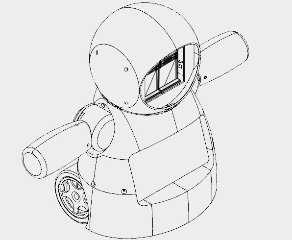
Four 8x8 LED matrix were used on robot's face.
The structure was divided in two parts (face back plate and face front plate) 3D printed using black PLA. It took me around 2.5 hours for 3D printing them, with 10% infill and no supports.
Due to space limitations, the connectors of the LED matrixes had to be dessoldered and had their position changed as described bellow:
- Remove the LED matrix;
- Dessolder input and output connectors;
- Re-solder thanon the other side of the circuit board, with the pins pointing the center of the board.
You can see the final result in the images.
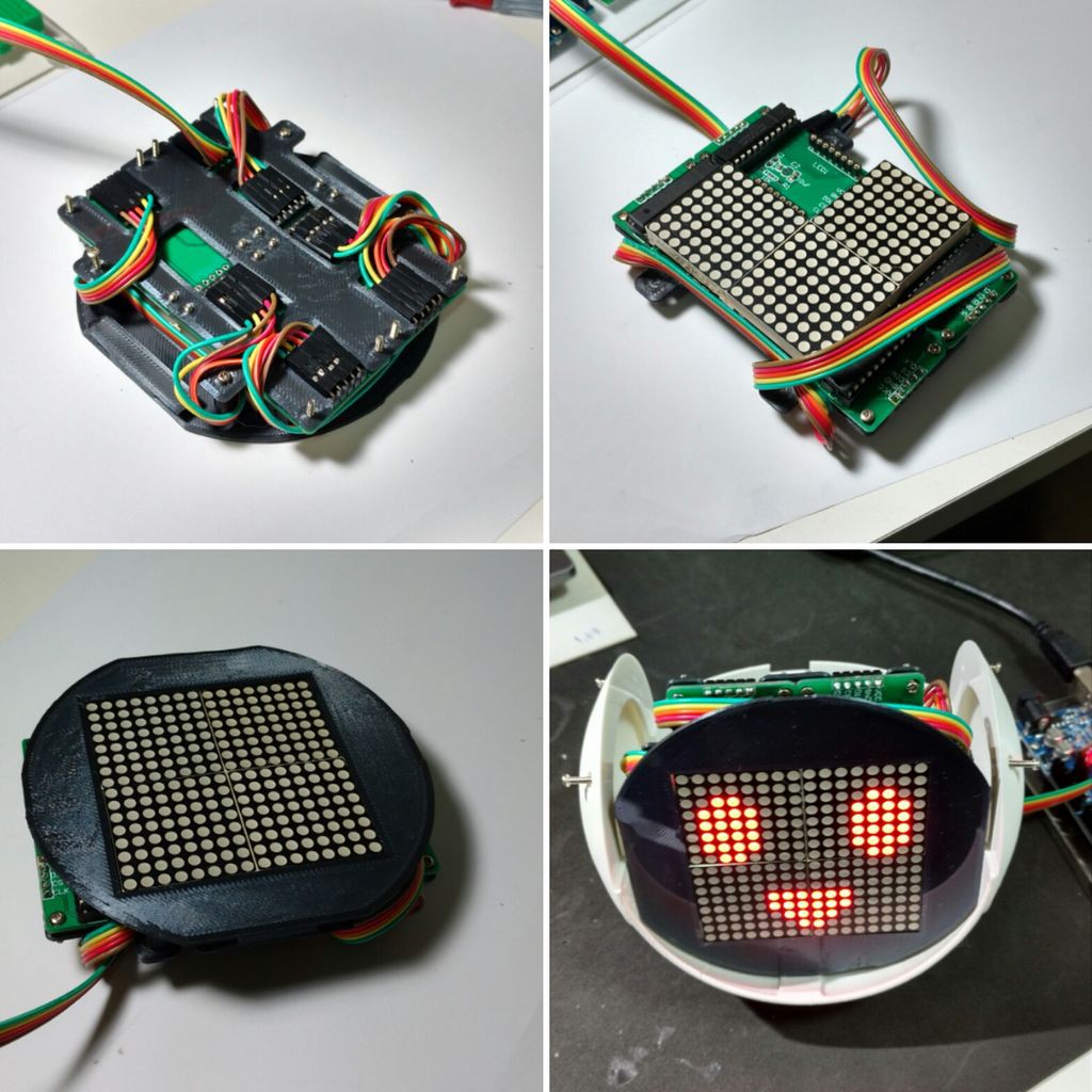
The four LED matrixes were then attached to the backplate, using 16 M2x6mm bolts. The pins were connected according to the schematics.
The first matrix was connected using a 5 wire male-female jumper. The male end was later connected to Arduino pins. The female end is connected on matrix input pins. The output of each matrix is connected to the input of the next one using a female-female jumper.
After the connection of the matrixes, the front plate is installed using four M2 bolts. Wrap the jumpers around the back and front pannels, so that there's no loose wires.
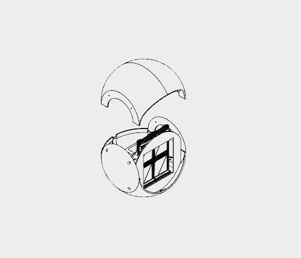
The face module is later installed inside the robot's head, as it will be explained on the next steps.
![]()
![]()
-
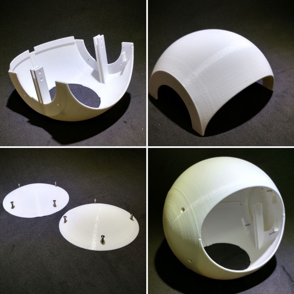
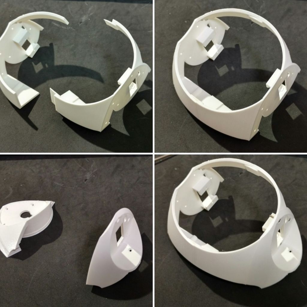
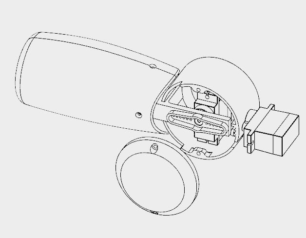
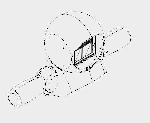
5Mounting the Head
![]()
![]()
The head of the robot was divided in eigth 3d printed parts, all of them printed in white PLA with 0.2mm resolution, 10% infill and no supports:
- Head top (right and left)
- Head bottom (right and left)
- Head cap (right and left)
- Neck axis 1
- Neck axis 2
It took me almost 18 hours for printing the 130 mm in diameter structure.
The top and bottom of the head are divided in two parts. They're glued together using super glue. Apply the glue and let it rest for some hours.
The side caps are then mounted using bolts attached to the sides of head's top and bottom. This way, the head can be disassabled for repair by removing screws attached to head top parts. Before closing the head, assemble the face of the robot (described in previous step), and the bust (discribed in next steps).
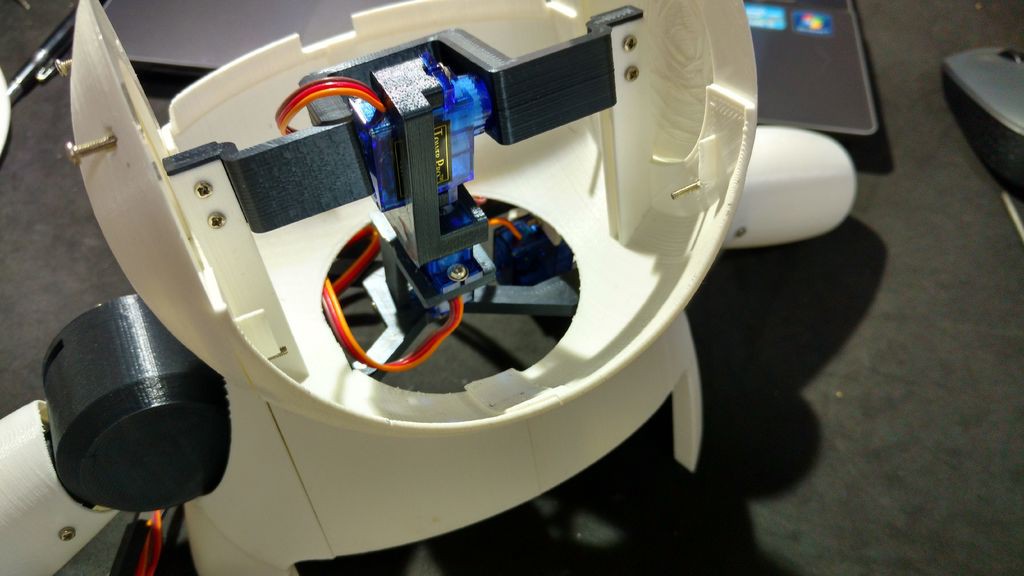
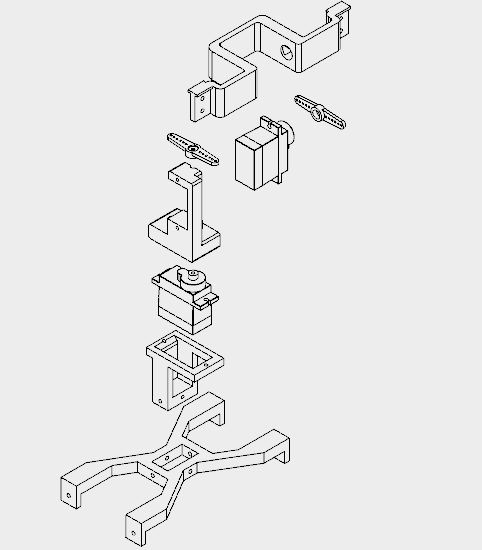
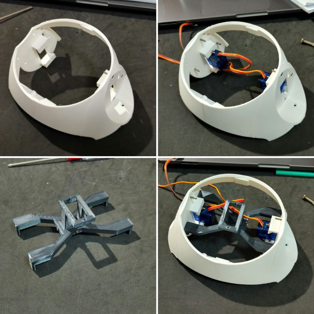
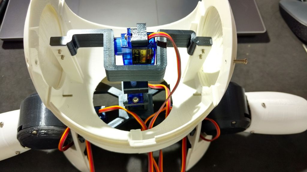
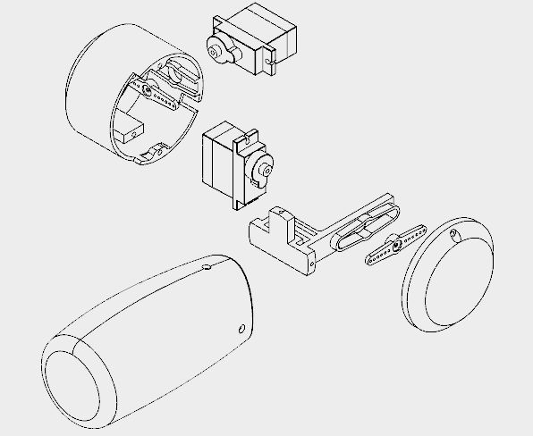
Servomotor #5 was attached to Neck axis 1. I positioned the servo in the middle of the axis, then attached the horn and used a screw to lock its position. I used two M2x6mm bolts to mount Neck axis 2 on that servo motor. Servomotor #6 is attached to Neck axis 2 the same way.
Neck axis 2 was later connected to Neck center, as it's show on next step.
The face module is installed inside the head.
![]()
![]()
![]()
![]()
![]()
-
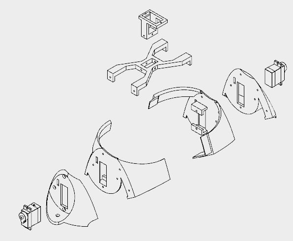
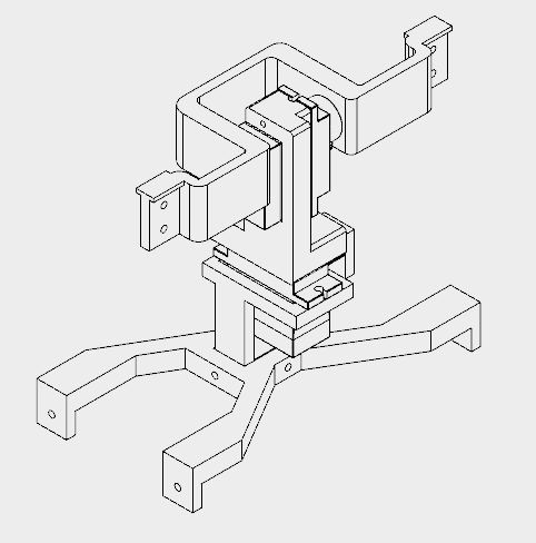
6Assembling the Burst and Shoulders
![]()
![]()
![]()
Bust and shoulder took me around 12h to be printed.
This section is made of five different parts:
- Bust (right/left)
- Shoulders (right/left)
- Neck center
- Neck axis 3
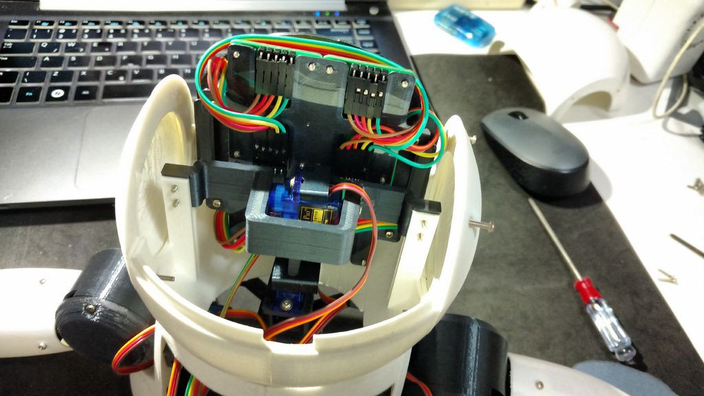
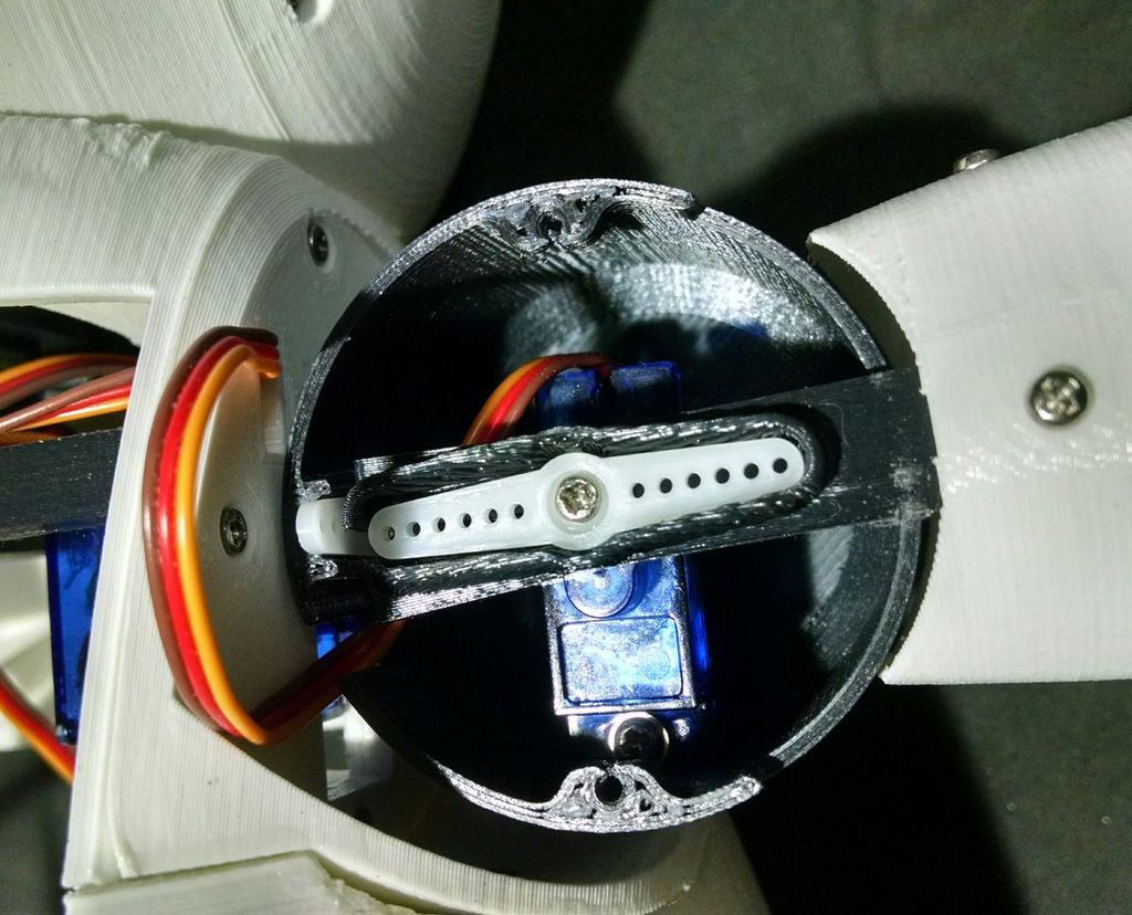
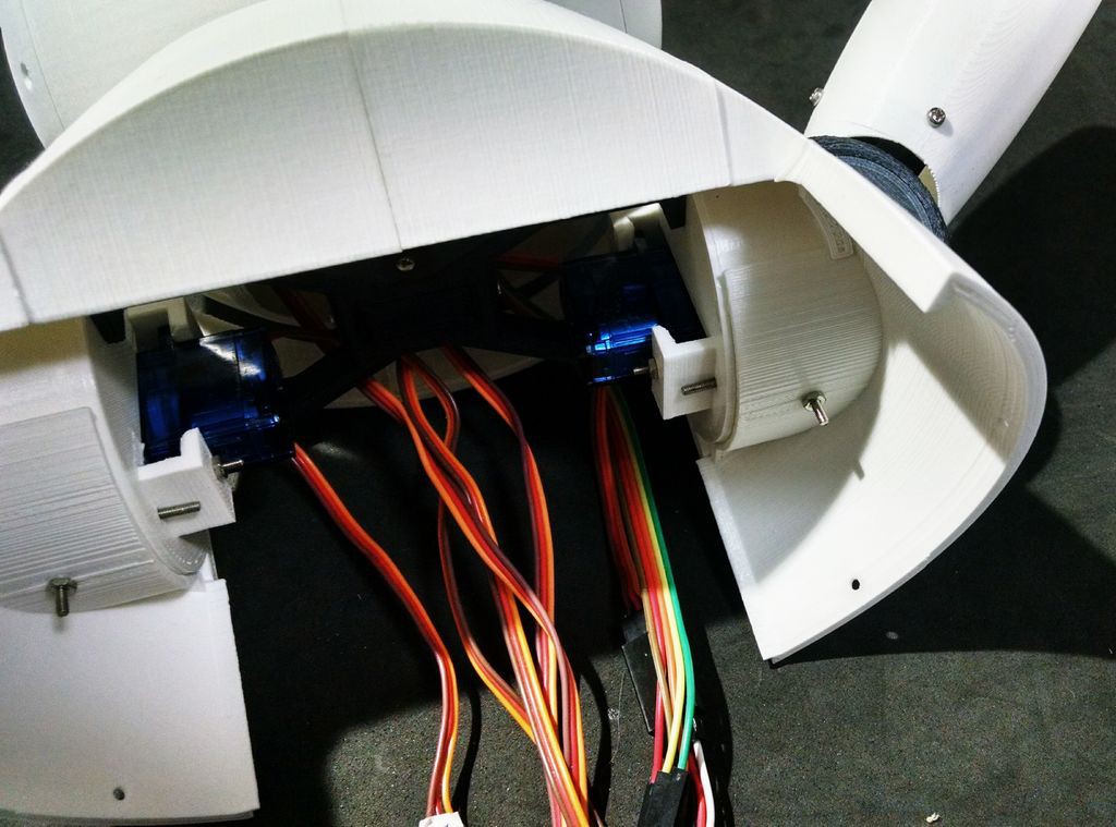
The bust parts were glued using superglue. Shoulders were attached on the sides using M2x10mm bolts, and the servomotors (Servomotor #2 and #4) were installed on each side. They pass through a rectangular hole on each shoulder (the wire is actually quite difficult to pass), and are attached using M2x10mm bolts and nuts.
Center neck has a rectangular hole, in which the Neck axis 3 part is inserted. Four M2x6mm bolts were used to link those two parts. After that the center neck was attached to the shoulders. It uses the same bolts used to mount the shoulder on the bust. Four M2x1,5mm nuts are used to lock its position.
Servomotor #6 was connected to Neck axis 3 using two screws. Then I installed Neck axis 3 inside Neck center rectangular hole, and used four M2x6mm bolts to lock its position.
![]()
![]()
![]()
-
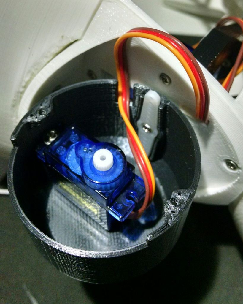
7Assembling the Arms
![]()
![]()
![]()
It took me around 5 hours to print each arm.
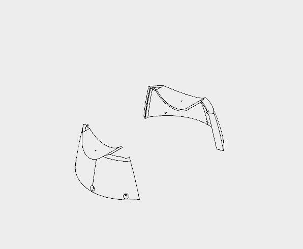
Each arm is made of four pieces:
- Shoulder cup
- Shoulder cap
- Arm axis
- Arm
Arm axis is centralized and mounted on the arm itself using three M2x6mm bolts. A servo horne is attached at the other end of the axis.
A servomotor (#1 and #3) is installed inside the Shoulder cup using some screws, and then have its horned (the one attached to the arm axis) installed. There is a hole on the cup for the installation of other horne, which is attached to the servo (#2 and #4) already mounted on the shoulders, as it was shown in previous step.
There's another hole on the Cup (and on the Shoulder) for passing the cables of the servos. After that, the Cap is installed to close the shoulder of the robot, with two M2x6mm bolts.
![]()
![]()
![]()
-
8Mounting the Chest
![]()
![]()
The chest is the part that links the bust to the bottom (wheels and base) of the robot. It's made of only two parts (right and left parts. I printed them in 4 hours.
The shoulders of the robot fits on upper part of the chest. There is a hole for a bolt that helps the alignment and fixation of thos parts. Although it's recomended to glue those two parts.
The bottom of this parts have six holes, which are used for the connection to the wheels, as it will be shown later.
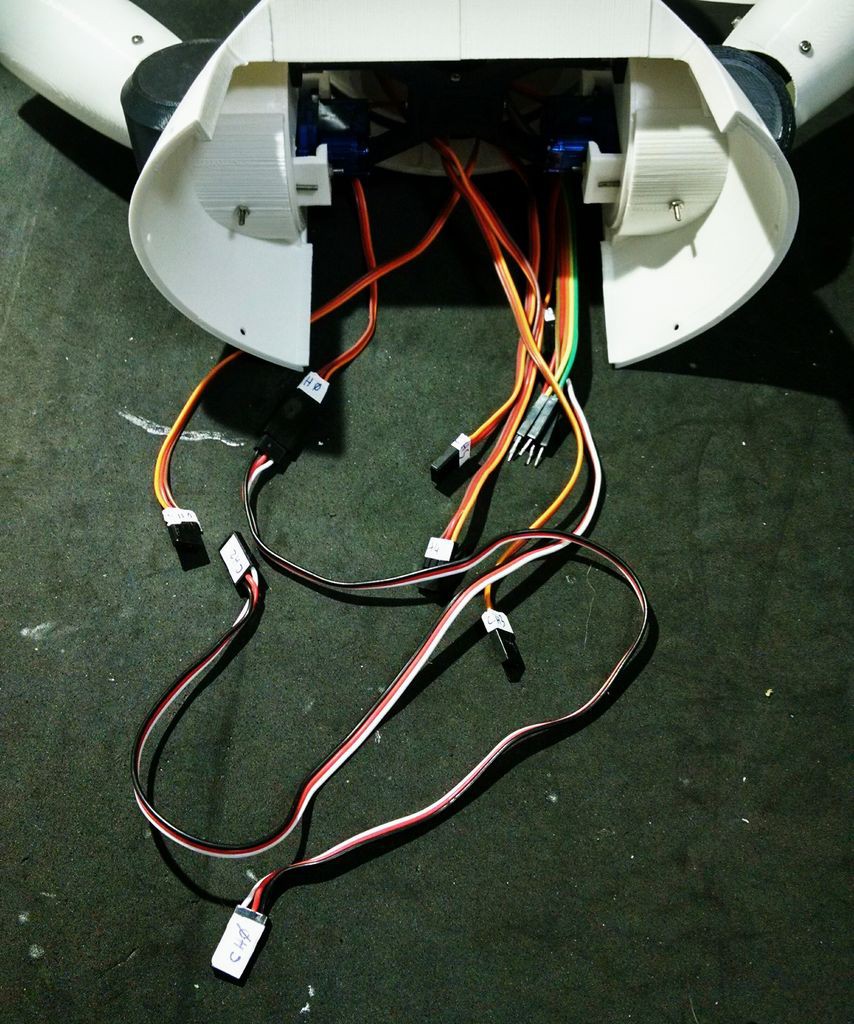
At this point I labelled the servomotors with some stickers, in order to make the connection of the circuits easier.
![]()
![]()
![]()
-
9Assembling the Wheels
![]()
![]()
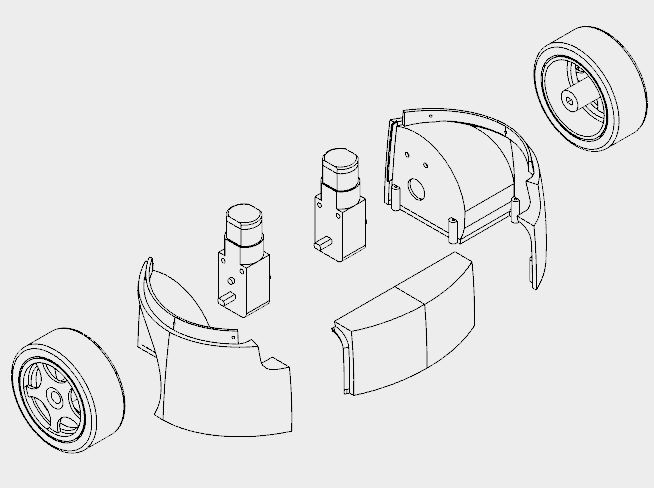
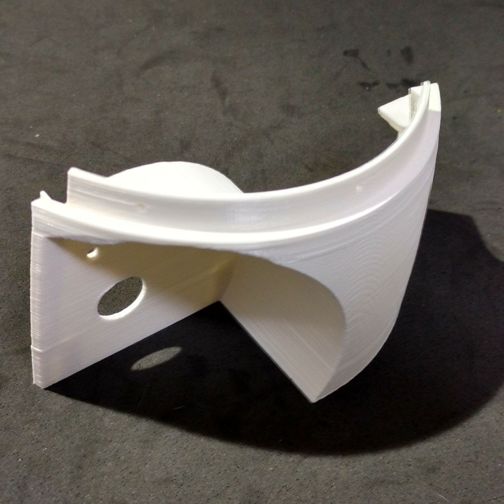
The wheels of the robot uses three 3d printed parts:
- Wheels (left/right)
- Front
It took me around 10h to print those parts.
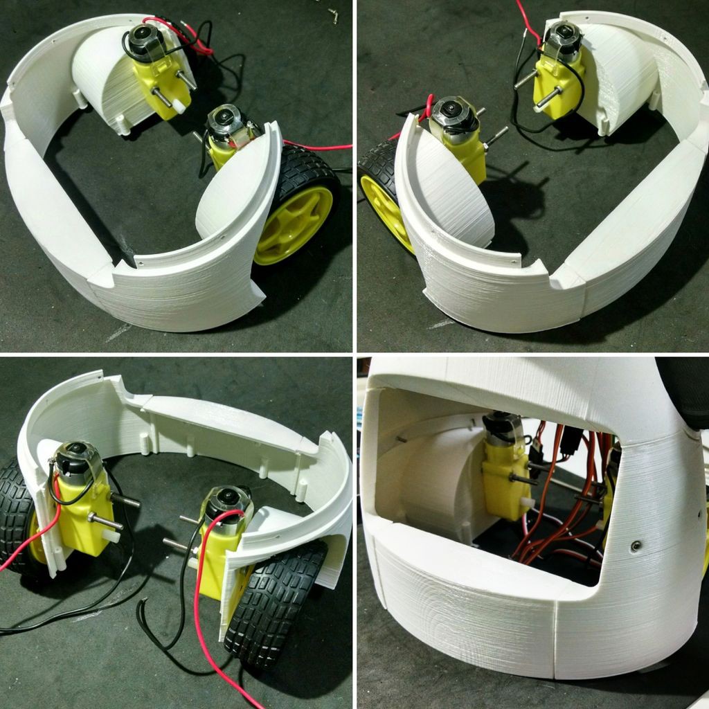
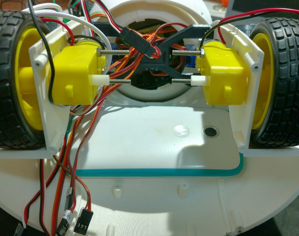
I followed the following steps for assembling the wheels:
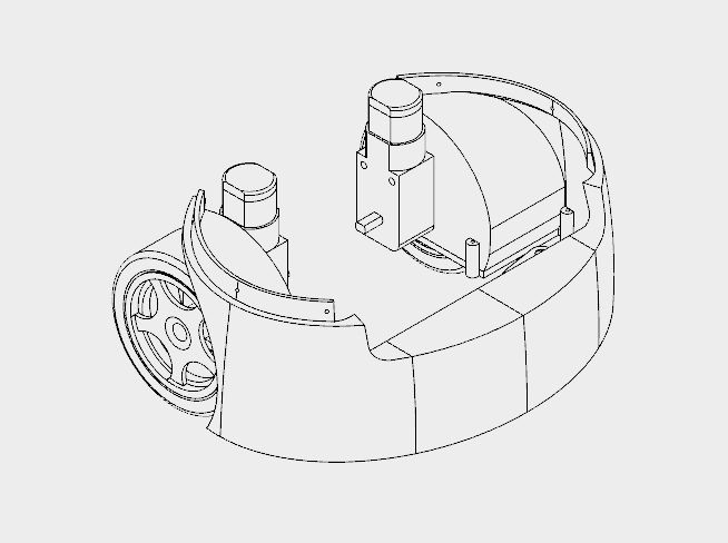
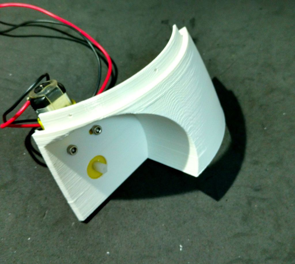
- First I had to solder some wires to DC motors connectors. Those wires were later used for powering the motors using a H-bridge circuit;
- The motors were then attached to the structure using two M3x40 bolts and nuts for each. Actually a shorter bolt might be used (but I found none online);
- After that I glued the front pannel, which links the other parts of the structure;
- This part has some holes on its top. They are used for its attachment to the chest, shown previously. Six M2x6mm bolts were used for the connection of both sections.
![]()
![]()
![]()
![]()
-
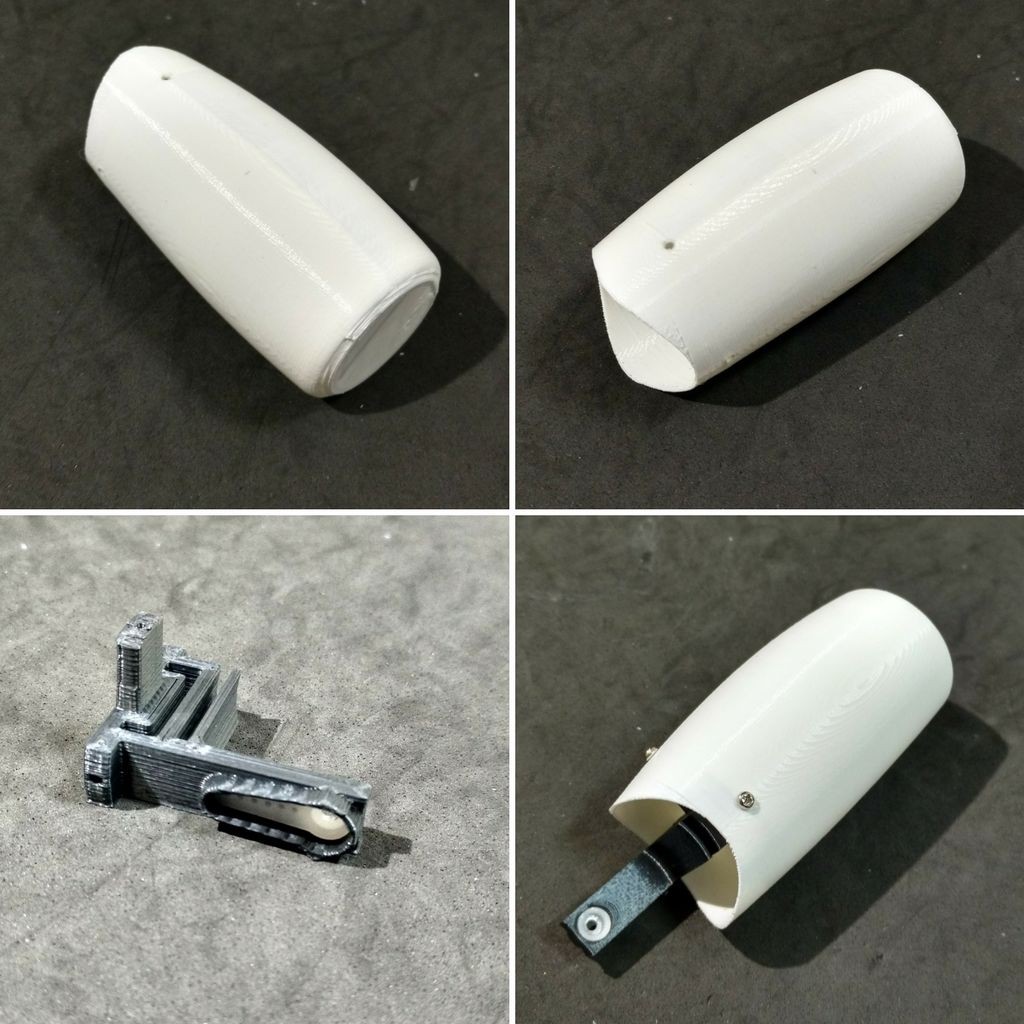
10Phone Holder
![]()
![]()
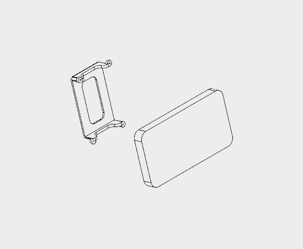
The phone holder is a single 3d printed part, and it takes around 1 hour to print.
The robot has a smartphone at it's belly. It was designed for a Motorola Moto E. It has a 4.3" display. Other smartphones with similar size might fit as well.
The phone holder part is used to hold the smartphone in the desired position. First the smart phone is positioned, then it's pressed against the body of the robot using the phone holder and four M2x6mm bolts.
It's importart to connect the USB cabe to the smartphone before tightening the bolts. Otherwise it will be hard to connect it later. Unfortunatly the space is very limited, so I had to cut part of the USB connector away... :/
![]()
Joy Robot (Robô da Alegria) 2017 edition
Open source 3D printed, Arduino Powered robot for the kids!

Discussions
Become a Hackaday.io Member
Create an account to leave a comment. Already have an account? Log In.