 igorfonseca83
-
11Mounting the Base
![]()
![]()
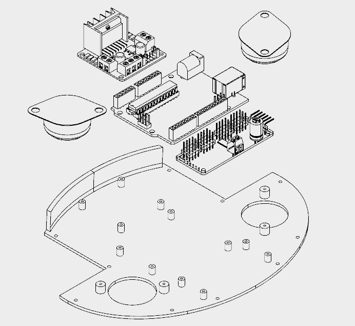
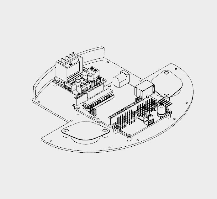
The base has only one 3D printed part. It took me around 4h to print that part.
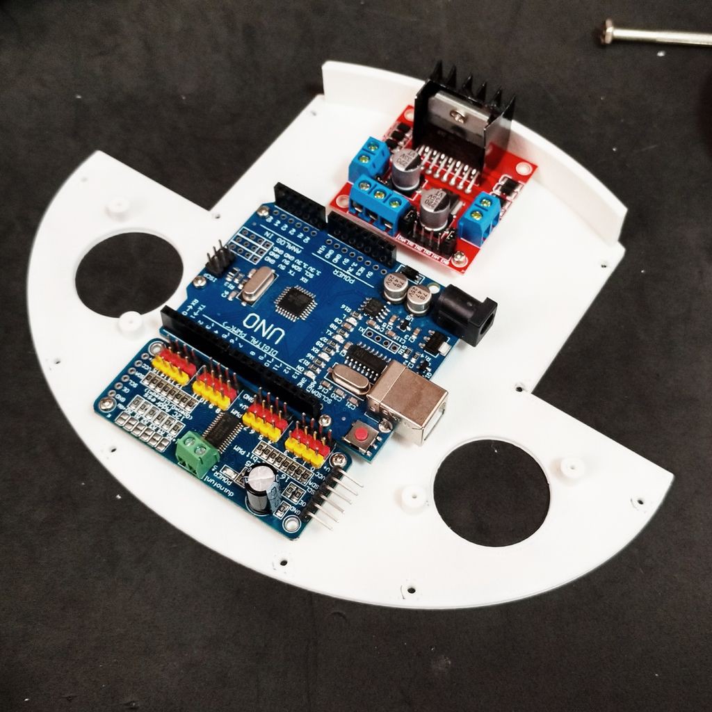
It has several holes for the installation of other components, like the ball wheels, and circuit boards for instance. The following procedure was used for assembling the base:
- Install the 16 channel servo controller using four M2x6mm bolts;
- Install the L298N h-bridge circuit using four M2x6mm bolts;
- Install the Arduino Uno using four M2x6mm bolts;
- Install the protoshield on the top of the robot;
- Wire up the circuits (as it's described a couple steps later);
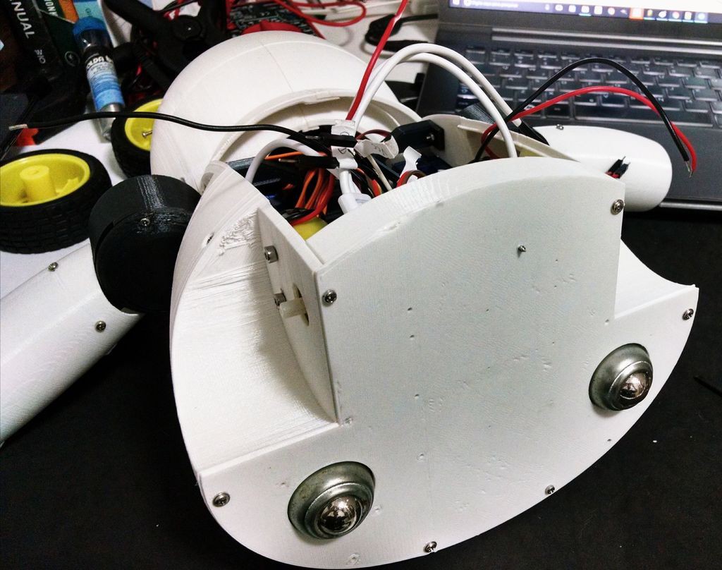
- Installe the ball wheels using two screws for each one. The wires were arranged so that they are traped between the base and the screws used in the installation of the wheels;
- Base was attached to wheels section using some screws.
![]()
![]()
![]()
-
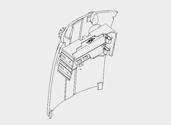
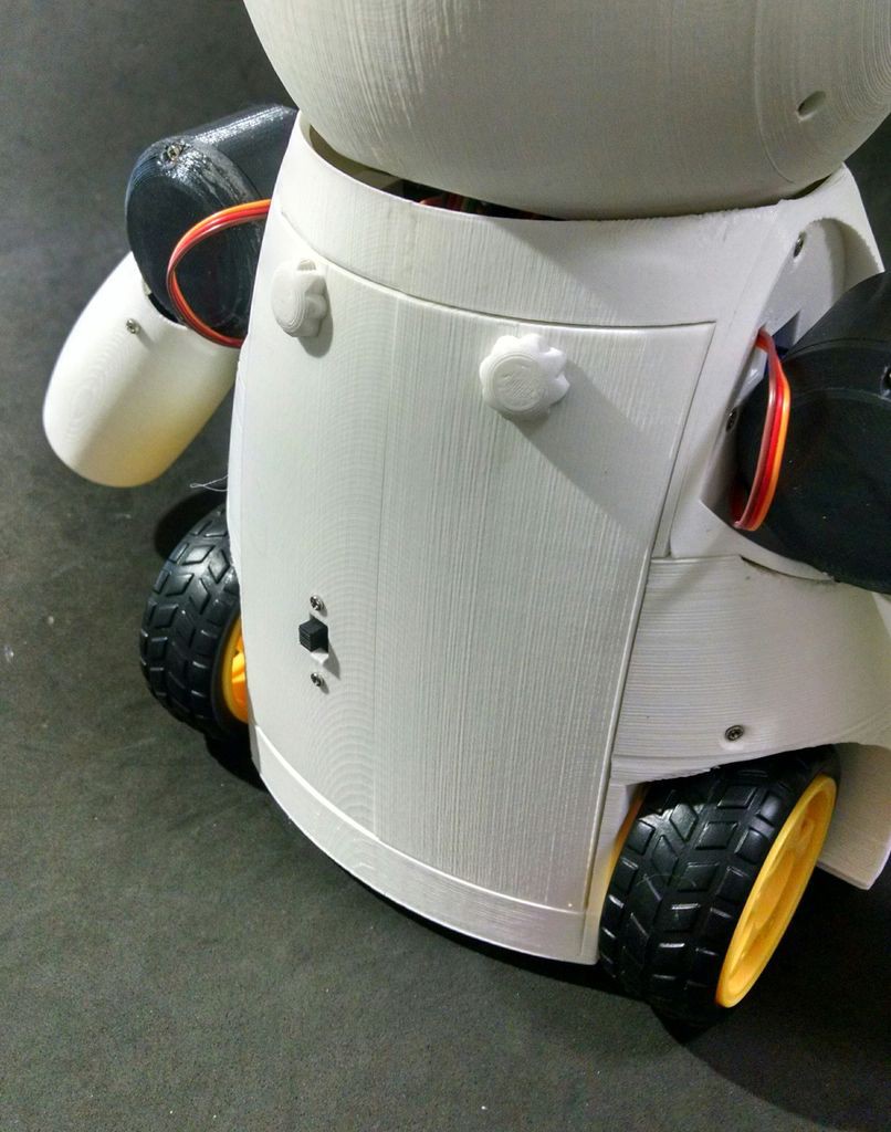
12Back and Power Pack
![]()
![]()
The back cover of the robot was designed so that one can easilly open it for accessing the circuits, recharging the batteries, or turning the smartphone on/off.
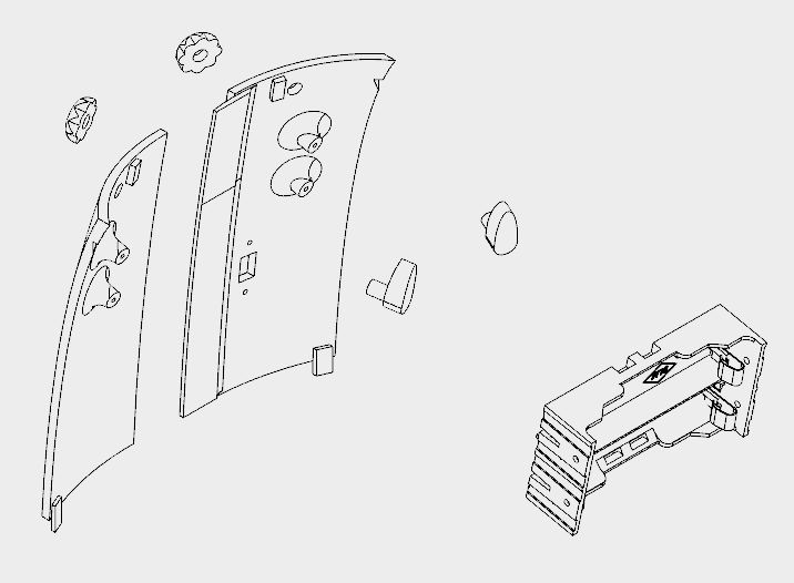
It's made of six 3d printed parts:
- Back (left/right)
- Knobs (x2)
- Locks (left/right)
It took me around 5h30 for printing the parts. Right and left back parts were glued using superglue. Wait until the glue is completly dry, or the cover will break easilly.
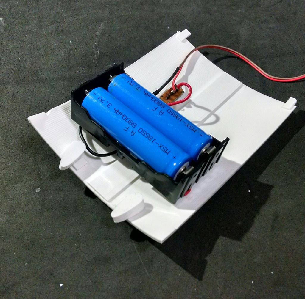
The power pack consists of two 18650 batteries and a battery holder. I had to solder some wires (between battery #1 negative pole and battery #2 positive pole). The negative pole of the power pack was connected to Arduinos GND (using some wires and jumpers). A on/off swich was installed between the positive pole and Arduino's Vin input.
The on/off switch was attached to back 3d printed parts using a M2x6mm bolt and M2x1.5mm nut. The battery holder was attached to the back using four M2x6mm bolts.
The cilindrical part of the locks had to be sanded with a sand paper for a better fitting. They pass through the holes on the cover. The knobs are connected and glued on the other side.
The cover fits to the back of the robot. The knobs can be turned for locking the lid, protecting the insides of the robot.
![]()
![]()
-
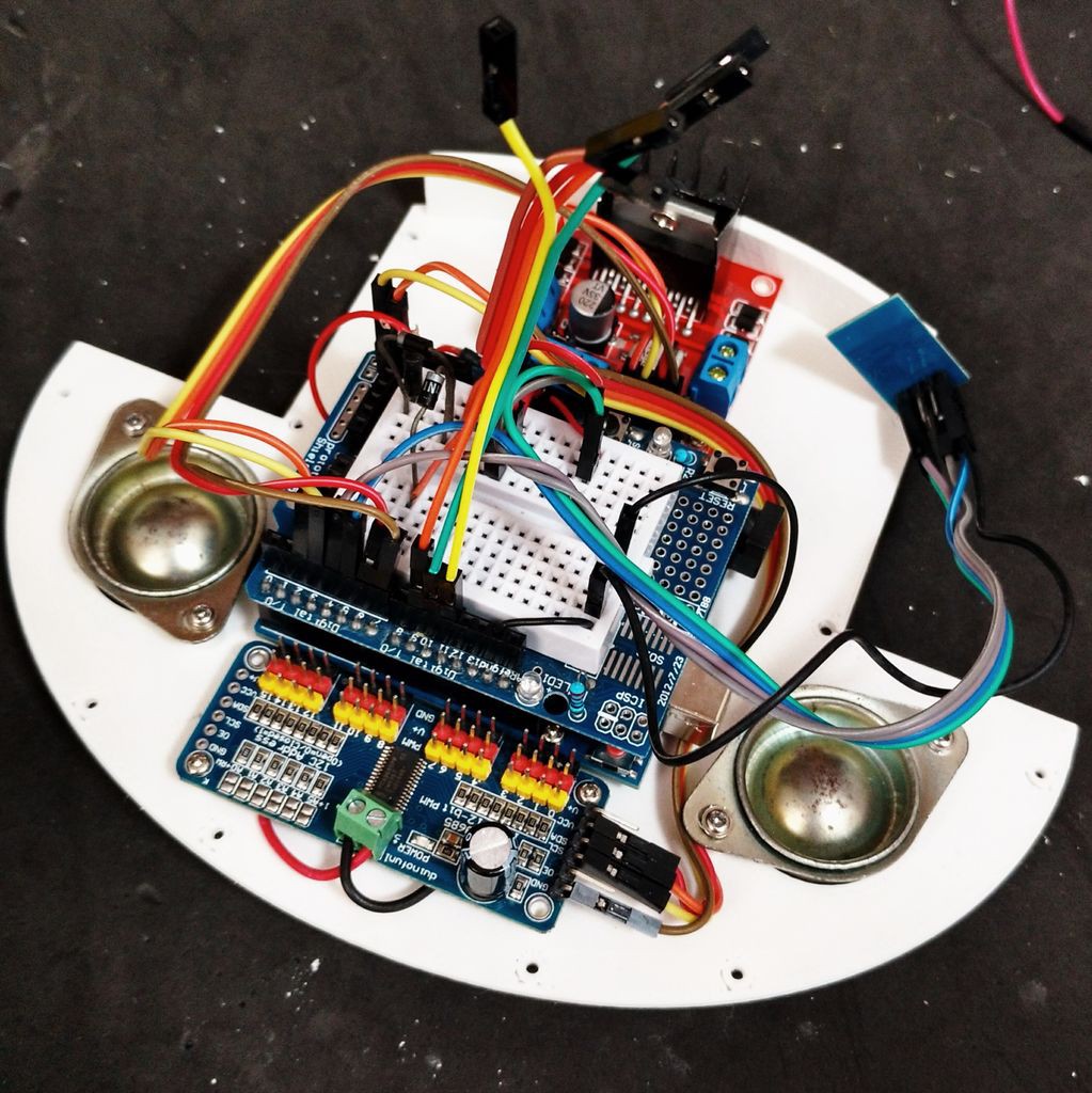
13Wiring Up the Circuits
![]()
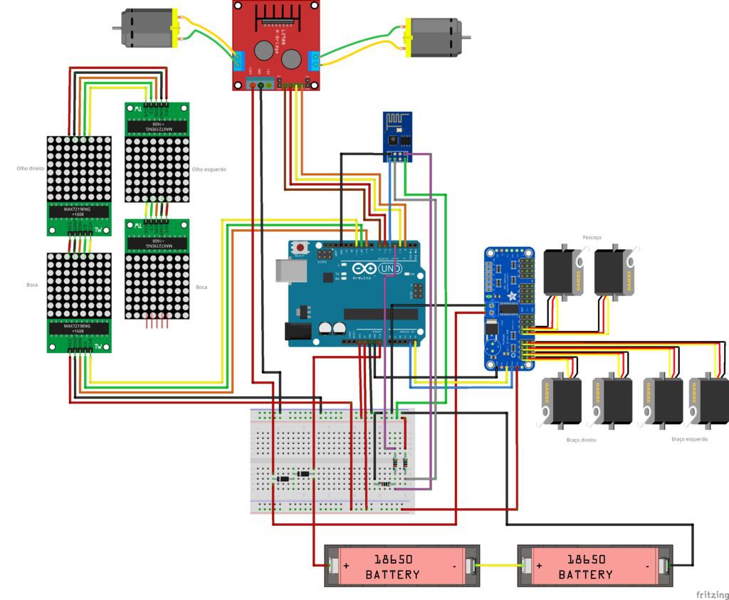
The circuit was wired up according to the schematics.
Arduino:
- Arduino pin D2 => L298N pin IN4
- Arduino pin D3 => L298N pin IN3
- Arduino pin D6 => L298N pin IN2
- Arduino pin D7 => L298N pin IN1
- Arduino pin D9 => MAX7219 pin DIN
- Arduino pin D10 => MAX7219 pin CS
- Arduino pin D11 => MAX7219 pin CLK
- Arduino pin D4 => ESP8266 RXD
- Arduino pin D5 => ESP8266 TXD
- Arduino pin A4 => SDA
- Arduino pin A5 => SCL
- Arduino pin Vin => Battery V+ (before diodes)
- Arduino pin gnd => Battery V-
ESP8266-01
- ESP8266 pin RXD => Arduino pin D4
- ESP8266 pin TXD => Arduino pin D5
- ESP8266 pin gnd => Arduino pin gnd
- ESP8266 pin Vcc => Arduino pin 3V3
- ESP8266 pin CH_PD => Arduino pin 3V3
L298N h-bridge
- L298N pin IN1 => Arduino pin D7
- L298N pin IN2 => Arduino pin D6
- L298N pin IN3 => Arduino pin D3
- L298N pin IN4 => Arduino pin D2
- L298N pin +12V => Battery V+ (after diodes)
- L298N pin gnd => Arduino gnd
- L298N OUT1 => Motor 1
- L298N OUT2 => Motor 2
MAX7219 (first matrix)
- MAX7219 pin DIN => Arduino pin D9
- MAX7219 pin CS => Arduino pin D10
- MAX7219 pin CLK => Arduino pin D11
- MAX7219 pin Vcc => Arduino pin 5V
- MAX7219 pin gnd => Arduino pin gnd
MAX7219 (other matrixes)
- MAX7219 pin DIN => MAX7219 pin DOUT(previous matrix)
- MAX7219 pin CS => MAX7219 pin CS (previous matrix)
- MAX7219 pin CLK => MAX7219 pin CLK (previous matrix)
- MAX7219 pin Vcc => MAX7219 pin VCC (previous matrix)
- MAX7219 pin gnd =: MAX7219 pin gnd (previous matrix)
16-channel servo controller
- Servo controller pin SCL => Arduino pin A5
- Servo controller pin SDA => Arduino pin A4
- Servo controller pin Vcc => Arduino pin 5V
- Servo controller pin gnd => Arduino pin gnd
- Servo controller pin V+ => Battery V+ (after diodes)
- Servo controller pin gnd => Arduino pin gnd
Some say the Sg90 servo can be powered between 3.0 and 6.0V, others between 4.0 and 7.2V. To avoid trouble I decided to put two diodes in series after the batteries. This way, the voltage for servos is 2*3.7 - 2*0.7 = 6.0V. The same is applied to the DC motors.
Notice this is not the most efficient way, but it worked for me.
-
14Arduino Code
Install the latest Arduino IDE. No library was needed for communication with ESP-8266 module or control of the DC motors.
I'll need to add the following libraries:
- LedControl.h: library used to control the LED matrixes;
- Adafruit_PWMServoDriver.h: library used to control the servo motors.
Arduino code is divided in 9 parts:
- RobodaAlegria.ino: this is the main sketch, and it call the other parts. Libraries are imported here. It also define and initialize global variables;
- _05_Def_Olhos.ino: this is where the matrixes for each eye are defined. Each eye is represented by a 8x8 matrix, and 9 options where defined: neutral, wide-eye, closed up, closed down, angry, borred, sad, in love, and dead eyes. There is a different matrix for right and left eyes;
- _06_Def_Boca.ino: this is where the matrices for the mouth are defined. The mouth is represented by a 16x8 matrix, and 9 options where defined: happy, sad, very happy, very sad, neutral, tongue out, open, wide-open, and disgusted mouth;
- _10_Bracos.ino: predefined movements for arms and neck are defined in this file. Nine movements, mov1() to mov9(), were configured;
- _12_Rosto.ino: in this file there are some functions for updating the face of the robot, combining the matrixes defined in _05_Def_Olhos.ino and _06_Def_Boca.ino;
- _13_Motores_DC: it defines the functions for ther DC motors;
- _20_Comunicacao.ino: a function for sending data to ESP8266 is defined in this file;
- _80_Setup.ino: it runs on Arduino power up. It set the inicial face and position of the motors of the robot. It also send commands for the connection to a given Wi-Fi network;
- _90_Loop: main loop. It looks for incoming commands from ESP8266 and call specific functions to control the outputs.
Download Arduino code. Replace the XXXXX by your wifi router SSID and YYYYY by router password on on '_80_Setup.ino'. Please check the baudrate of you ESP8266 and set it properly in the code ('_80_Setup.ino'). Connect the Arduino board to your computer USB port and upload the code.
-
15Android Apps
An Android smartphone was used to broadcast the video and audio from the robot to the control interface. You can find the app I used on Google Play store (https://play.google.com/store/apps/details?id=com.pas.webcam).
The screen of the smartphone may also be transmited to the control interface, so that the operator can see what's on the screen. You can also find the app I used to mirror the screnn on Google Play store (https://play.google.com/store/apps/details?id=com.ajungg.screenmirror).
An Android video game was also designed to interact with the robot. It's not yet very stable, so it isn't available for download.
-
16Control Interface
A html interface was designed for the control of the robot. Download interface.rar and extract all the files to a given folder. Then open it on Firefox. The interface is divided in two blocks. To the left there are displays for the camera and screen mirror. To the right there are controll buttons for the commands.
Textbox forms are used in that interface to enter IP address of the ESP8266 module ('Endereço IP Arduino:'), video/audio server from Android IP Webcam app ('IP Webcam (IP):') and Screen Mirror IP address ('Screen Mirror (IP):').
Under 'Ações predefinidas' tab user can select between 9 predefined body movements and 13 different faces. On 'Ações personalizadas' tab user can set a given angles for each of the 6 servos, and individually select between 9 eyes possibilities and 8 mouths variations. A javascript function runs whenever one of those buttons is clicked, and a message is sent for ESP8266's IP address.
Keyboard arrow keys are used for moving the robot forward or backward, and to rotate left or right.
When the interface is started, a warning is displayed, asking if the user wants to share the microphone. If this option is selected, sound intensity of the microphone will be used to send a preconfigured command to the robot. This command will trigger an animation, simulating speech movement on robot's face. A settings button on upper right corner might be used to set the sensitivity of the microphone.
This settings menu might also be used to configure the speed of arms and neck movements.
Joy Robot (Robô da Alegria) 2017 edition
Open source 3D printed, Arduino Powered robot for the kids!
Discussions
Become a Hackaday.io Member
Create an account to leave a comment. Already have an account? Log In.