Skyler Brandt
-
November 24, 2017
11/24/2017 at 08:02 • 0 commentsI've been continuing the trend of cleaning up the project by moving all the board designs and firmware into a single repository. The first reason for this is that the board designs are now revision controlled with git instead of copying directories. The second is that hopefully this reduces the confusion between what firmware is meant to run on which board revision.
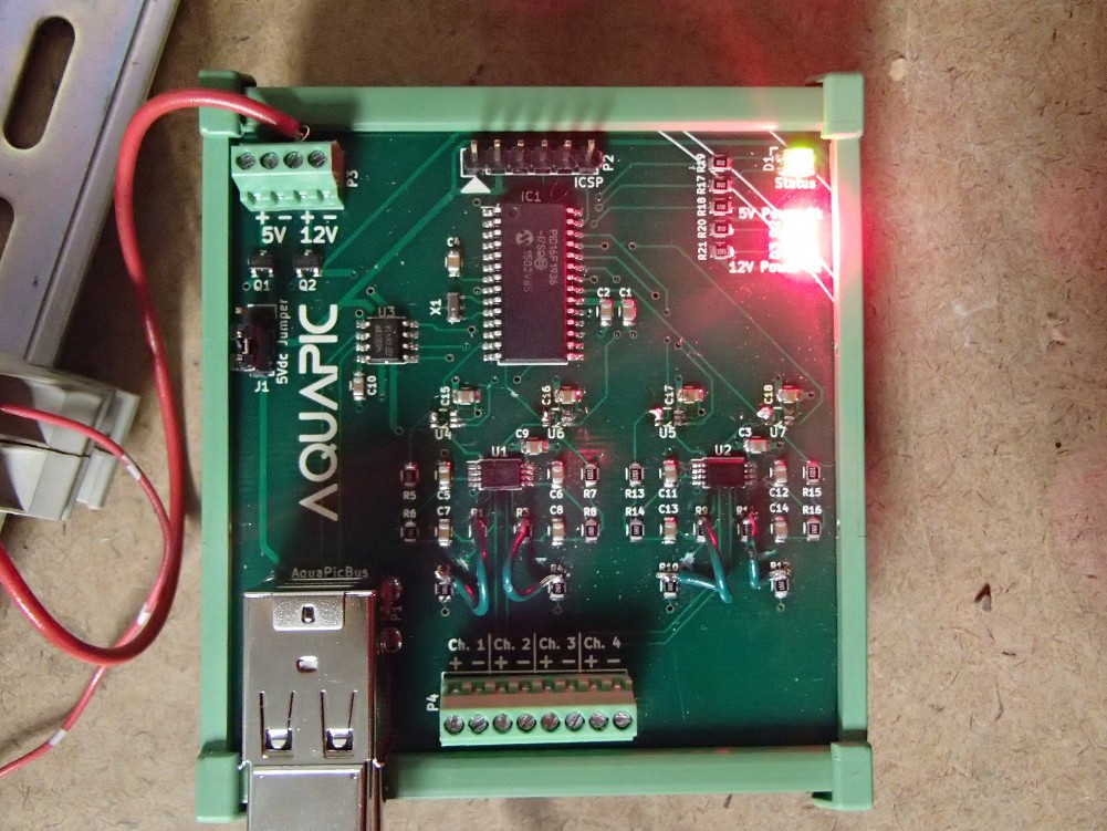
I also started replacing all the PIC16F microcontrollers with PIC32MM micros. So far the only card/module that is using a PIC32MM is the analog input card. The new PIC32MMs are about the same price as the older PIC16Fs but with a lot more power. More power probably isn't necessary but the analog input card performs quite of bit of 32 bit math include multiplication and division. The PIC16Fs sport an ALU that doesn't include any hardware multiplication and are kind of terrible at even 8 bit multiplication. The PIC32MMs shouldn't have any issue since the architecture has a single cycle multiplication unit. I briefly thought about using an ARM Cortex-M, but ARM is an entirely different ballgame than I'm used to.
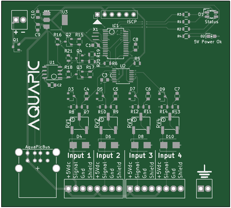
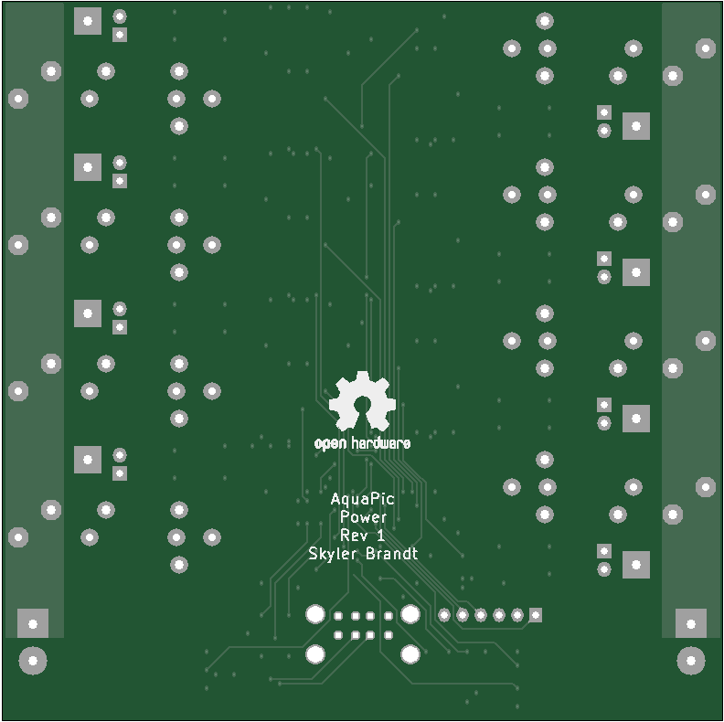
While redesigning the analog input card I decided to go with a dedicated ADC with 16 bit signed resolution. All of the analog temperature sensors I've looked at have a rather small resolution, i.e. voltage per degree C, so I decided that 16 bits was the easiest solution to overcome the small resolution and avoid implementing some sort of amplifier circuity. I also added protection on each of the inputs. Its pretty standard input protection with the exception of the potentiometer. The pot is used to vary the value of voltage divider and thus vary the input voltage to the ADC. This allows for increasing the ADC input voltage for devices that have a limited output. For example, the MCP9701 outputs a voltage around 2.8Vdc at 125°C. With the pot bypassed the ADC input voltage will be 1.89Vdc. Fairly close to its full scale voltage of 2.048Vdc. However, the pressure sensor I'm using to measure level will output almost 5Vdc at full scale. In this instance the pot can be used to add resistance to limit the voltage such that it doesn't go about 2.048Vdc but also maintain an ADC input voltage of 2.048Vdc at the sensor's full scale output.
---------- more ----------As always here are the board renders of the newly designed analog input card:
![]()
![]()
-
August 12, 2017
08/12/2017 at 22:31 • 0 commentsIn the past 10 months since my last update I've been working on a lot of things other than the AquaPic, but I've found some time off and on to mostly cleanup parts of the project. Both the main controller and card firmware can now be built without the need for a graphical IDE. I added the GPLv3 license to both the repositories, and fixed the README's as well. I also cleaned up quite a few things in the code as well. I refactored the water level module in the main controller to include water level groups similar to the temperature groups. This allows for multiple water levels to be monitored with less headache and hopefully a little more future proof. I refactored the way the AquaPicBus slave driver works. In not so many words, I abstracted the way responses are constructed. I also abstracted a few of the other functions/modules in the card firmware, such as the ADC, pins, and PWM. Lastly, back in July of last year I thought I bricked my RPi. However, it turned out that building the Linux kernel from source replaces the config file that resides in the root directory that tells the RPi how to start some modules such as the HDMI output. I don't know how I came to that conclusion but at some point last year I ended up fixing that as well.
-
October 29, 2016
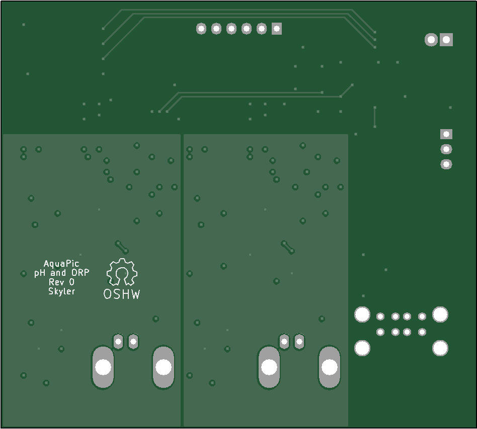
10/29/2016 at 23:07 • 0 commentsThis project has been on the back burner for the last few months, and for a while there the pot was completely off the stove. I haven't shelved the project though, and I've made some progress. I finalized the layout for the analog input and digital input cards. I finished the layout for the pH and ORP card, and I redesigned the power strip for the third time. I was trying to replace the Chinese SSR with my own triac design, but come to the realization that it was going to be a lot of testing and work that I didn't have time for. I did however combine everything onto one PCB. I fit everything onto a 10cm by 10cm board but I had to go to 4 layers to do so. The ph/ORP card also ended up being 4 layer. Lastly, I started to work on data logging for the main controller and finally have line graphs on the home screen on the controller.
![]()
![]()
![]()
![]()
![]()
-
July 22, 2016
07/23/2016 at 03:03 • 0 comments![]()
I title this picture "So Much Winning!" It has been a reoccurring theme with this build that my RS485 protocol is not functioning as intended but I'm optimistic that a small but somewhat large change will finally end my troubles. There is no longer a 9th bit used for address detection, and thus no longer a need to deal with parity. Backing up a bit, its been a rough road to this point. Just as before, when I thought that I had the communication figured out, my computer goes and updates itself, or I find out that building modules for the Raspberry Pi is an excellent way to make oneself mentally unstable. Back in March I patched the driver for the CH341 driver and had 9bit RS485 communication working on my main computer. However, since then, the CH341 driver has been updated back to kernel default with no parity support. Awesome. Why those few lines of code aren't part of the default driver is kind of dumb in my opinion. However, that wasn't the final nail in parity's coffin and I could re-patch the driver. It isn't difficult, its just a lot of waiting for things to download, and irritation.
My tipping point was attempting to build the CH341 driver for the Raspberry Pi. That was unnecessarily frustrating. I don't know everything I tried, but my bash history is full of thousands of commands I issued in an effort to get one little patch added to a driver. Most of my issues stemmed from the fact that the any compiled CH341 module I built didn't match the version of the Linux kernel itself or some other dependent module. If you don't already know, the header files for the Raspbian kernel are proprietary so there are multiple irritating hoops to jump through to get the exact right branch from Raspberry Pi's Github cloned. There are several forum threads and instructions online that detail ways to get it to work and I tried every one I could find. One person said he had to complete rebuild the entire kernel any time he wanted to update or add a module. That is completely asinine but in a last ditch effort I tried it, and brick the RPi. It still boots but its not right. That was the point when I decided that that 9th bit just wasn't going to happen.
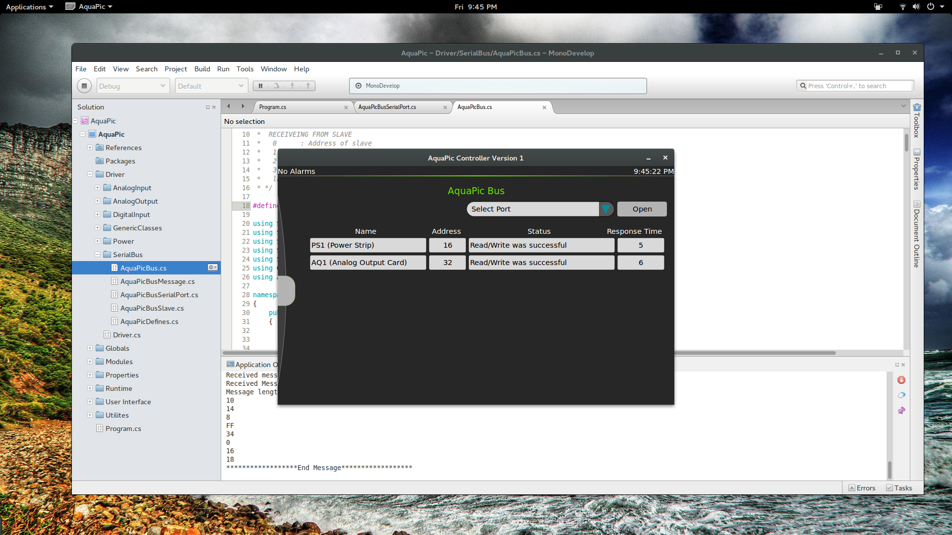
So the question became, what do I do to initiate an address detection. A common RS485 protocol is Modbus, and has two operating modes, ASCII and RTU. ASCII operates just like it sounds and sends ASCII characters. The message is basically a string. 192 would be 0x31, 0x39, 0x32. That mode is initiated, or framed, by sending a semicolon character, ':', to start and a CRLF to end. Simple ASCII characters. The issue with ASCII is that the number of bytes sent in a message can be high, so RTU is used instead. RTU sends the binary representation of message. 192 would be 0xC0. However, start and end framing can't be initiated by a character or number because that number can and will be in the regular message. RTU instead frames its messages with a 3.5 character delay. AquaPic Bus also uses binary messages, so I decided to try framing with a time delay. I thought it was going to be difficult to implement, but it turned out to be fairly easy. Most of the changes happened in the slave code. It has a simple counter that counts up every millisecond but is reset once a byte is received, so that when the serial lines are quiet for at least 10 milliseconds the slave modules start waiting for a address. The next byte is assumed to be the address and if it matches, it handles the message. If it doesn't, it waits for the next delay. The master code was even easier. I simple commented out a few lines and added a 12 millisecond delay before I write out a message. Once I made those few changes, I downloaded the code to the two slave modules, hit debug on the master program, flipped to the AquaPic Bus status window and was met with the glorious sight of "Read/Write was successful". Queue the happy dance. Woo Woo.
-
March 19, 2016
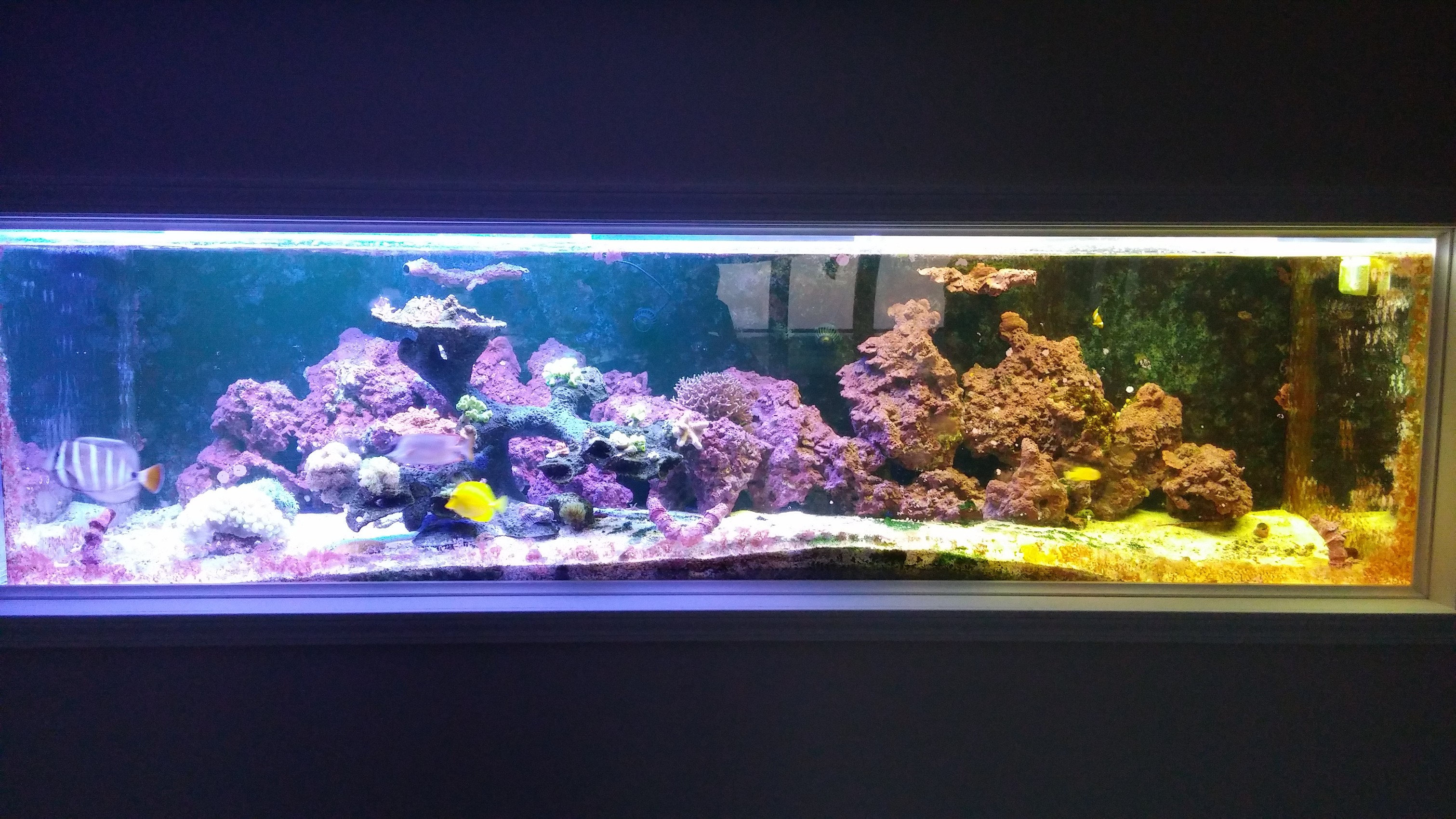
03/19/2016 at 22:07 • 0 commentsProgress has again been waylaid by life. My wife and I just moved to our new place and everything is in boxes. Probably will be in boxes for awhile longer. Moving sucks. A huge positive to our new house is that it has a 300 gallon aquarium built in in the basement. The tank is healthy, but it does need some work. There is a lot of coraline algae growth on the viewing glass. There is also not enough flow, too much sand, too small of skimmer, and the list goes on. The pictures suck, but in my defense, tanks are fairly difficult to photograph. Especially with a phone. Currently I'm running two different kinds of lights; 10K T5 florescents on the right and two LED features on the left. That's why the colors are a little off from side to side.
![]()
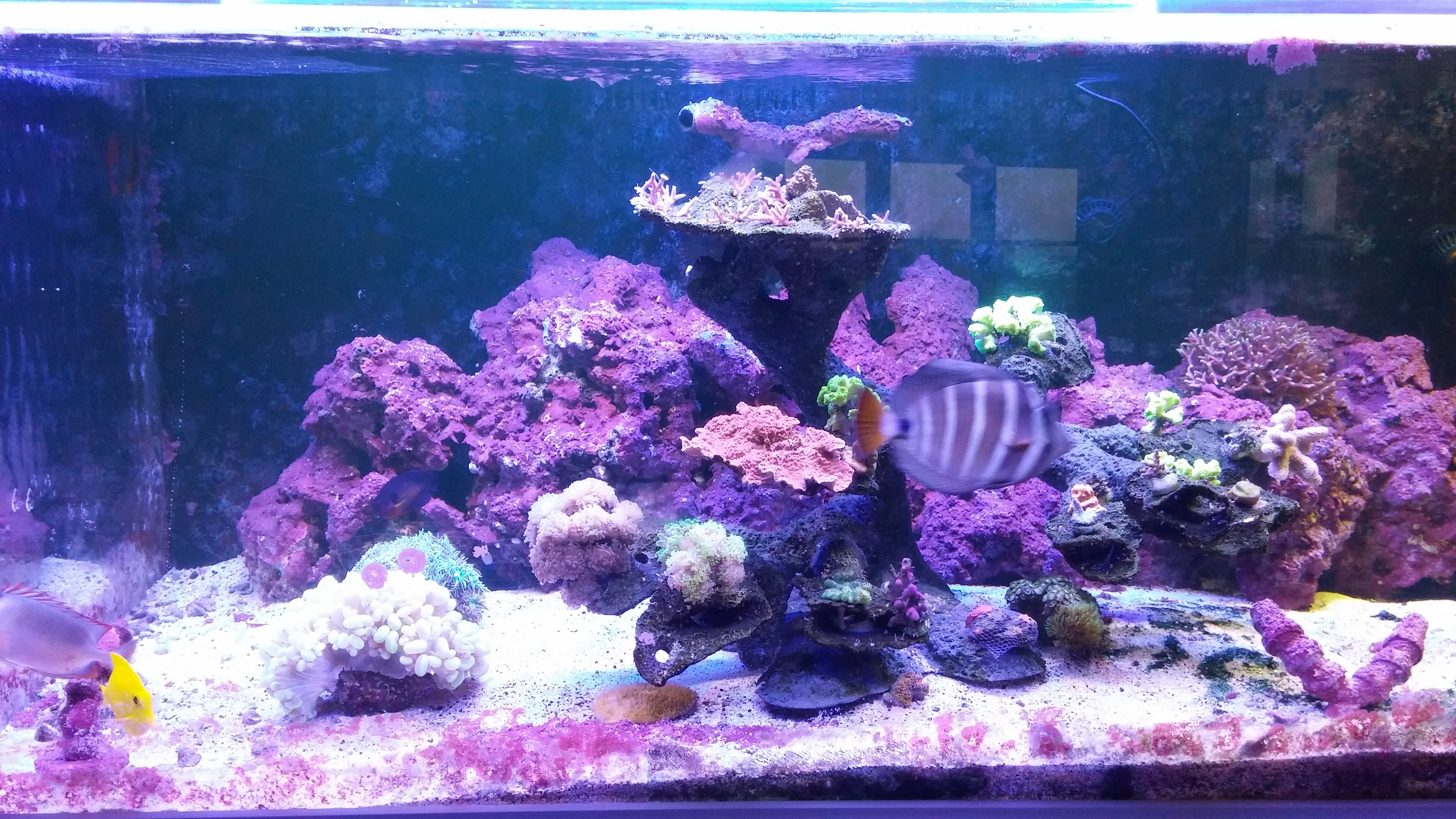
And a close up on left side with all coral.
![]() I've been making good use of my free time though by making the user interface pretty.
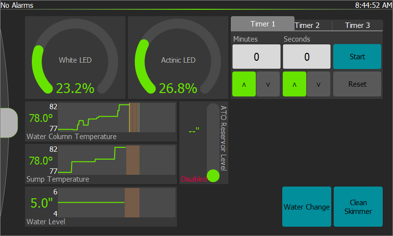
I've been making good use of my free time though by making the user interface pretty. New Home Screen. This is a work in progress. I'm not sure about the placement of "widgets", or the overall look.
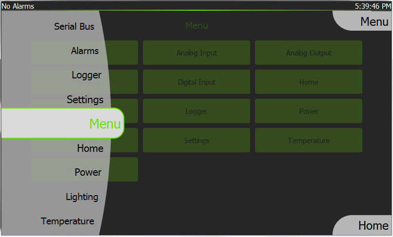
New Side Menu:![]()
![]()
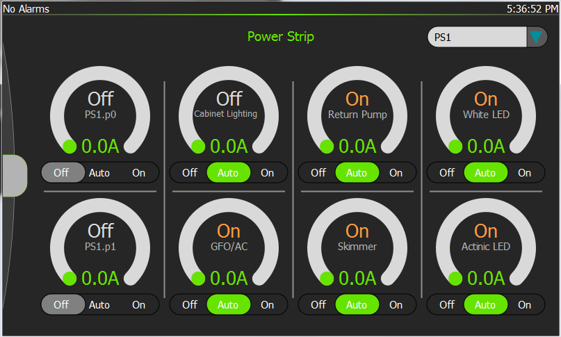
New Power Screen:
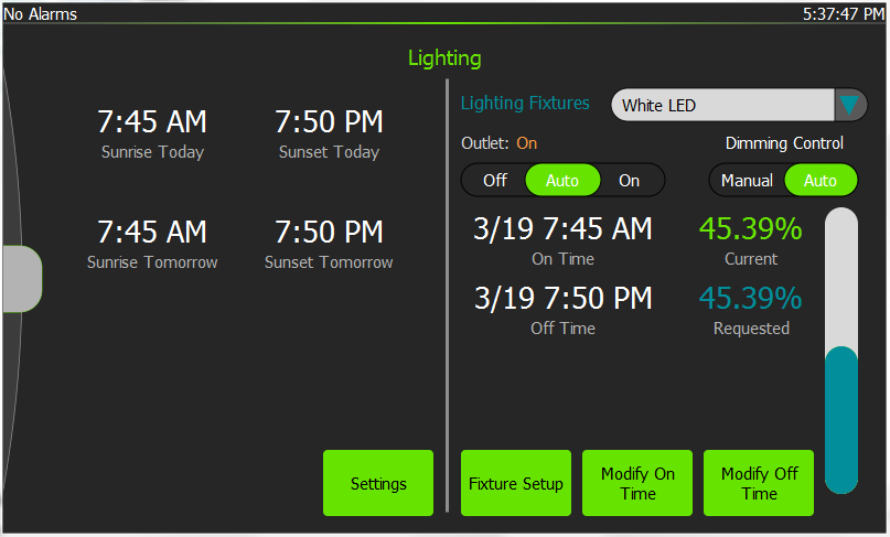
And New Lighting Screen:![]()
![]()
Just a few screens I've been changing. Everything else is just boring or looks similar to the video I made a few months ago. I can't wait to get everything unpacked so I can get back to finishing this project. The good new is that I now have a fish room, so mounting everything is so much easier.
-
March 1, 2016
03/01/2016 at 23:11 • 0 commentsIf I’d known what was all involved with 9bit communication, I probably would have chosen a different option. However, despite all the bugs, issues, and lack of support, I finally have a fairly reliable communication protocol. After my last post I realized that I could test my hypothesis that it was the USB hub on the RPi. I could simply unplugged the WiFi dongle, and see if the problem persistent. As expected, there was no improvement. The USB hub wasn’t my issue. I don’t remember exactly what all I did after that but there was a lot of beating my head against my desk. At some point I realized I could reproduce communication faults on my Windows PC when I was using the parity hack, counting the bits in each byte and setting either even or odd parity to get the desired mark or space parity. I also found that the power strip slave was hanging, and restarting it would get it working for a while. I concluded that both the parity hack and the slave code were causing issues and set out to address both.
I expected that fixing the hanging slave module would be an easy fix, and for the most part it was except for one small detail I overlooked. To address the issue I added a simple check of the 9th bit as part of the received byte handler to double check that it wasn’t an address byte. However, I introduced one seemly small bug when implementing that. When I first made the change I was reading the 9th bit after I got the received byte off the microcontroller’s internal FIFO buffer. This is a big oversight as the microcontroller updates the status word containing the state of the 9th bit as the FIFO buffer is read, so when I checked the 9th bit it was actually for the next byte. That took me a while to find. Also, since I’m checking every byte now for the 9th bit, I removed the auto-address detection.
Fixing the parity hack was a chore. I decided that I needed to get mark and space parity to work in the Mono framework. The reason mark and space parity aren’t currently implemented in the Mono framework is because it requires the CMSPAR flag to be defined, which it isn’t with the POSIX source. Since I didn’t want to recompile the MonoPosixHelper library, I set out writing my own helper library that could be used to set the parity. It was actually pretty easy to write, pretty much copy and paste. I used a lot of Mono’s existing C code and a blog post by Thomas Lochmatter to modified a few lines to include the CMSPAR, mark/space parity, flag. Code after break.
I built the parity library and using Mono’s documentation for PInvoking native libraries, tried to get it working on my Linux machine, but was only met with DllNotFoundExpection. I had pulled a rooky mistake and compiled the source as an object instead of a shared library. I also didn’t realize that you have to include a lib prefix to the library file name in order for the Mono framework to find that it. Running the application with the log level set to debug help find both these issues pretty quick.
$ MONO_LOG_LEVEL="debug" mono AquaPic.exeI also find out some other useful information. I had gone through all the steps that the docs lists to add a shared library so that dlopen() can find, but that isn’t required. The first place that the Mono framework searches is the application launch directory. Simply add the library in the same directory as the application .exe. After I fixed the lib prefix and built the source as a shared library, Mono was able to use my parity library, but it still didn’t workAt this point I was completely lost and went back to my Windows machine and using the parity hack. I wanted to try to get the parity hack to work, since it still wasn’t working under either Linux or Windows. Backing up a little bit, when I was first looking though the serial C code for Mono, I noticed that the termios flags are set immediately instead of waiting for the write buffer to be empty. Based on that code, I made the assumption that Windows closed magic probably also set the parity immediately, so I added a 10ms delay in the thread. That small delay fixed the hack parity. I don’t know why I didn’t think about that early, since it was such a no brainer easy fix. I think this was also the point in the story when I fixed the 9th bit bug in the slave module mention early. With Windows reliable working, I went back to Linux to see if I could get something work there, but still nothing worked. Not even the parity hack which only used the more common odd and even parity.
RS485 is an old technology and apparently everyone just agrees that it’s dead because there’s very little in the way of anything on the internet. I was Googling anything and everything that I thought might lead me down the path to figuring out what was the issue. On a whim I did a search about the ch341 Linux driver and parity and sure enough that wild stab in the dark was my issue. Linux includes the driver for the ch341 transceiver chip, but the driver doesn’t support parity. Luckily, Karl Palsson had already had this issue and provides a patch to add parity support. Patching the Linux source was a learning experience, but once I had the driver patched, everything worked. I was finally able to talk to the slave modules with the Mono framework on Linux.
I’m currently in the middle of a move so I haven’t had the chance to test any of this on the RPi. I’m fairly positive it will work though, and even if my library doesn’t work, the parity hack reliable works now. I can’t wait for the next big issue to rear its ugly head.
---------- more ---------
/****************************************************************** * Helper library to set Serial port parity in the Mono framework * on Linux. * * Largely based upon Mono framework's serial.c and the * set_attributes() function: * https://github.com/mono/mono/blob/master/support/serial.c * and Thomas Lochmatter's blog post about mark and space parity * on Linux: https://viereck.ch/linux-mark-space-parity/ * * Build command: * gcc -shared -rdynamic -fPIC AquaPicParityHelper.c -o libAquaPicParityHelper.so * Also the lib prefix in the output file name seems to be required * for the Mono framework to find the library. * * CMSPAR is define locally because I figured that would lead to * less issues. Another option is to define _BSD_SOURCE or * _SVID_SOURCE before including the termios and unistd headers. *****************************************************************/ #include <termios.h> #include <unistd.h> #define CMSPAR 010000000000 /* mark or space (stick) parity */ /* This is a copy of System.IO.Ports.Parity */ typedef enum { NoneParity = 0, Odd = 1, Even = 2, Mark = 3, Space = 4 } LinuxParity_t; int SetLinuxParity (int fd, LinuxParity_t parity); int SetLinuxParity (int fd, LinuxParity_t parity) { struct termios newtio; if (tcgetattr (fd, &newtio) == -1){ return 0; /* false */ } switch (parity) { case NoneParity: /* None */ newtio.c_cflag &= ~(PARENB | PARODD | CMSPAR); break; case Odd: /* Odd */ newtio.c_cflag |= PARENB | PARODD; newtio.c_cflag &= ~CMSPAR; break; case Even: /* Even */ newtio.c_cflag |= PARENB; newtio.c_cflag &= ~(CMSPAR | PARODD); break; case Mark: /* Mark */ newtio.c_cflag |= PARENB | PARODD | CMSPAR; break; case Space: /* Space */ newtio.c_cflag |= PARENB | CMSPAR; newtio.c_cflag &= ~PARODD; break; } if (tcsetattr (fd, TCSANOW, &newtio) < 0) { return 0; /* false */ } return -1; /* true */ } -
February 6, 2016
02/06/2016 at 10:31 • 0 commentsThe following update post was the ramblings of an extremely frustrated, under-equipped, and marginally trained hobbyist, and probably completely off base. Please disregard anything I said. I'm fairly certain I missed diagnosed the issue and am hopefully headed in the right direction now. Those words haven't been muttered before. Update to follow soon.
TLDR - If you want to use a USB-WiFi dongle and a USB-RS485 dongle at the same time on the RPi, it best to rethink the plan. Multiplexing those will only lead to issues...maybe.
Now that the backlight control is finished for the LCD, I was ready to do some final bench testing of the controller. I wanted to let it run for a while, maybe a week, to see what issues I ran into before I let this thing control my fish and coral's livelihood. The test was successful for about 50ms before everything went awry. I kept having communication faults between the RPi and the slave modules, but it wasn't consistent. For the first minute or so I would have a few intermittent timeouts or crc errors. Then it would magically fix itself and everything would run smoothly for about 10 minutes. After a good while without any faults, around the 12 minute mark, the communication would go off the rails again and start throwing errors again. Only now it wasn't as sparsely intermittent, but every 2nd or 3rd message would fault. Needless to say, I was lost on the issue. My first thought was that the received event in the serial class was the issue, because its already a hacky mess of a workaround to begin with. I changed some code around and tried again without the received event but the issue seemed to be worse. I fiddled with small changes here and there, but still had communication faults. I then decided that debugging on the RPi was only a handicap, so I swapped to my Windows PC and BAM! no issues. I removed as much of the hacky workarounds that I could and tried again on the RPi but it still didn't consistently work. I should now mention that this wasn't the only issue I was having. I was also having difficulty SSHing into the RPi. It would either timeout and not connect or take forever. It was at this point that I realized that if I was doing a lot on the SSH connection, the controller would start presenting comm faults. Finally, I concluded that the most likely candidate to cause me intermittent issues was the USB multiplexer try to handle the bandwidth of the WiFi, RS485, and touchscreen. It just can't keep up with all that traffic. There are other obvious difference between that RPi and my PC, Linux vs. Windows, .NET vs. Mono, but I don't think any other those are cause this issue. My way out of this is going to be the UART pins on the GPIO header. Fingers crossed I'm chasing the right lead, and its not something else.
-
January 30, 2016
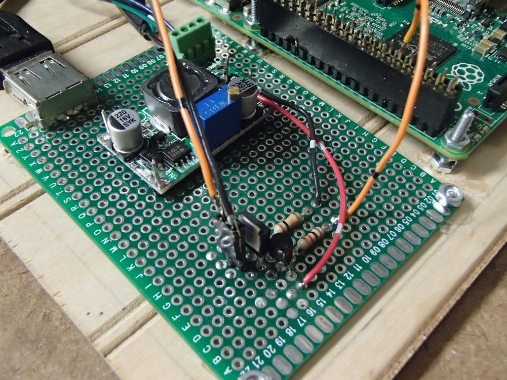
01/30/2016 at 22:58 • 0 comments![]() The little boost DC-DC converter fixed all my low voltage issues for the RPi and touchscreen. I was surprised that was such an easy fix. Getting a MOSFET paralleled with the backlight controls on the touchscreen was not and turned out to be a bit more involved than I expected. Most of the difficulty was self induced though. The best solution I could come up with for bodging a SMD SOT-23 was three pads on a SOIC breakout board. It was ugly but it probably would have worked. However, problems arose when I referenced the MOSFET and driver circuit off neutral of the power supply I would normally use but then powered the RPi from a different power source. I didn't catch my mistake at first, and instead concluded that my bastardized SMD work was the culprit. So I ordered a proper through-hole FET and once again it didn't work. That was when I finally realized my mistake, switched my power to the correctly referenced source, and everything worked as expected. Now when the screensaver come on, the backlight turns off and then when I touch the screen the screensaver goes off and the backlight switches on. I designed the gate circuit a little different than most other p-channel gate control. The gate is normally connected to ground though a resistor. Then a transistor is placed on the high side to pull the gate up and shut the MOSFET off. That way while the RPi is booting or something happens to the script that controls the GPIO, the backlight will fail on.
The little boost DC-DC converter fixed all my low voltage issues for the RPi and touchscreen. I was surprised that was such an easy fix. Getting a MOSFET paralleled with the backlight controls on the touchscreen was not and turned out to be a bit more involved than I expected. Most of the difficulty was self induced though. The best solution I could come up with for bodging a SMD SOT-23 was three pads on a SOIC breakout board. It was ugly but it probably would have worked. However, problems arose when I referenced the MOSFET and driver circuit off neutral of the power supply I would normally use but then powered the RPi from a different power source. I didn't catch my mistake at first, and instead concluded that my bastardized SMD work was the culprit. So I ordered a proper through-hole FET and once again it didn't work. That was when I finally realized my mistake, switched my power to the correctly referenced source, and everything worked as expected. Now when the screensaver come on, the backlight turns off and then when I touch the screen the screensaver goes off and the backlight switches on. I designed the gate circuit a little different than most other p-channel gate control. The gate is normally connected to ground though a resistor. Then a transistor is placed on the high side to pull the gate up and shut the MOSFET off. That way while the RPi is booting or something happens to the script that controls the GPIO, the backlight will fail on. -
December 30, 2015
12/31/2015 at 01:31 • 0 commentsFinals and the Christmas season have not been conducive to progress. I really need two solid days to rearrange and organize the underside of my tank to make room for the controller. Regardless, I have managed to get a little bit done in my free time. I laid out the analog and digital input boards. They are both really simple, and I'll send them out to get made after I get what I have done now up and running. I also wrote all the firmware for both cards. The code was extremely simple as well since most of it was copy and pasted from the other bits I've already finished. I haven't decided whether I'm going breadboard the cards and test the code that way, or just wait until I have PCB's and test then. The age old struggle between the right way and laziness.
The Raspberry Pi supply voltage is a little on the low side because of all the shotty connections between the power supply and the Raspberry Pi, so I order a little boost power puck thing to get the voltage back up to 5Vdc. I also wanted a way to automatically turn off the backlight when the screensaver came on, so I started re-purposed ramses0's xscreensaver-pi-hdmi script to control a GPIO pin to fire a MOSFET. The MOSFET will be paralleled with a switch that is already on the back of the touchscreen but is normally inaccessible. I still need to find a p-channel MOSFET to get this to work. I have quite a few SMD p-channel but no though-hole, so I've yet to find a good way, haven't investivataged all that hard yet though, to bodge one onto some protoboard or another sort of prototyping option.
-
November 25, 2015
11/25/2015 at 23:53 • 0 commentsI'm 95% done with my first prototype. Everything is assembled, and mostly working. I had quite a few issues and bugs to get to this point though. As I highlighted in my post two days ago, my RS485 protocol didn't work on the Raspberry Pi because mark and space parity isn't implemented under the Mono frame work. I took the easy way out and simply counting the number of high bits in the byte. Then I set the parity to either odd or even to get the desired 9th bit.
The next issue was all because I sometimes buy cheap "quality" Chinese parts. The original power supply I ordered to power the controller didn't work like I wanted it to. It was a dual supply, +5Vdc and +12Vdc, but for some reason I couldn't tie the commons together. I didn't look into, or care why, and instead ordered two separate power supplies. Another nail in the coffin of the original power supply was the switching frequency. It's in audible range, probably around 10ish KHz, and extremely annoying.
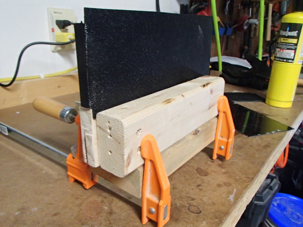
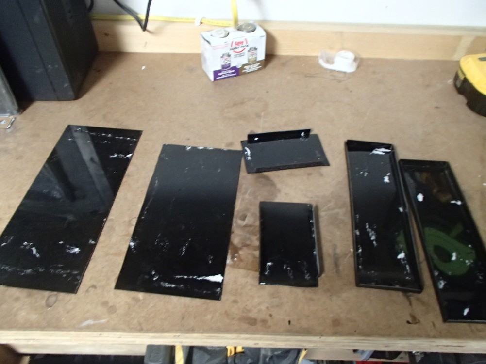
The power strip went together fairly easy. I don't really like the case but it works. Its made out of ABS plastic sheets. I cut all the pieces out, then bent over tabs on the edges to make a surface to glue everything together.![]()
![]()
I then used pipe cement to glue everything together. The top and bottom are held on by 6-32 machine screws. I threaded the plastic so I didn't have to use any nuts. It's definitely not elegant, but I don't cool machines to do anything prettier, like a CNC machine or a lazer cutter. And no, a home hobby 3D printer is not cool.
![]()
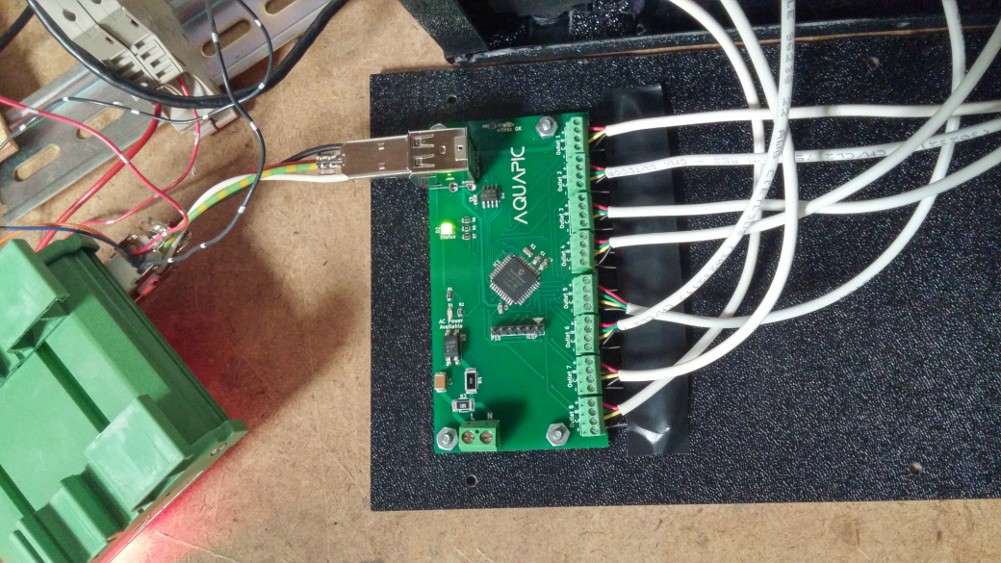
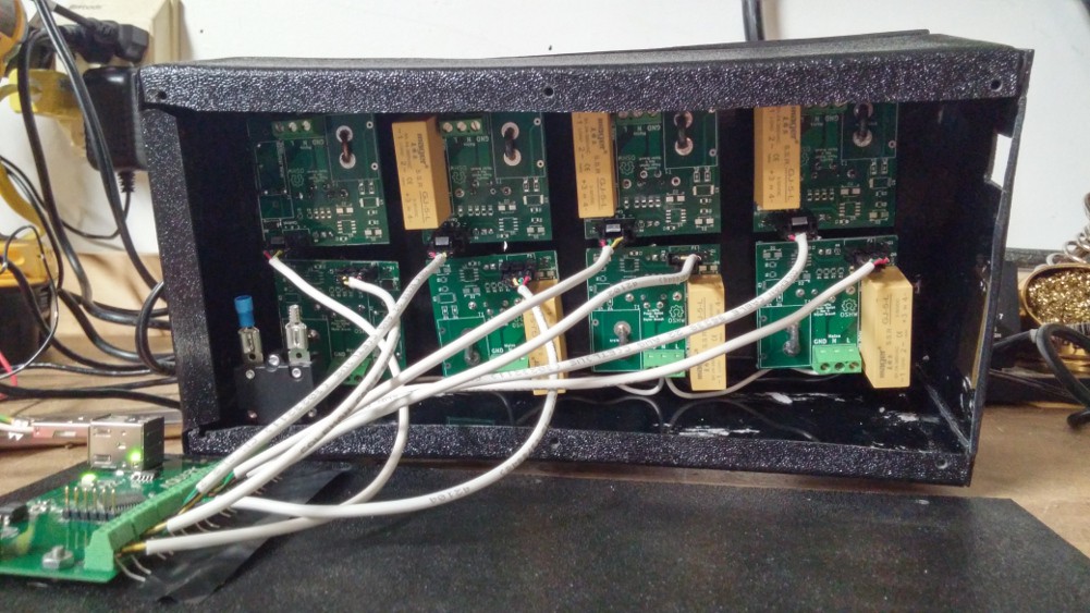
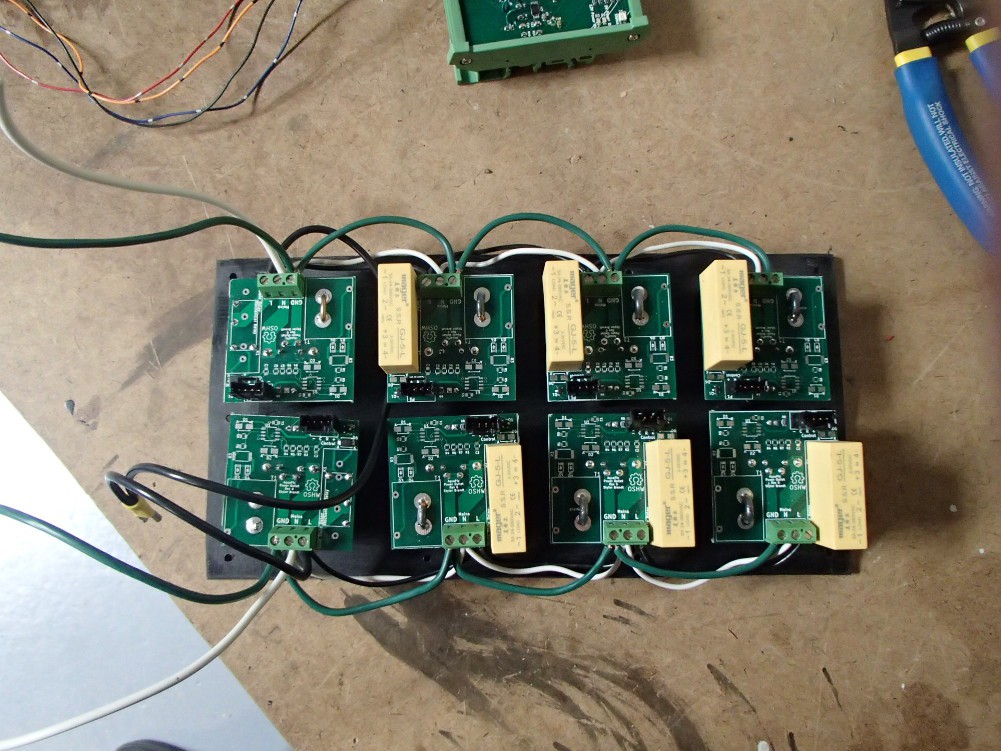
Before I wired all the outlets up to mains, I wired up the control circuity and tested that. I had to parallel 10K resisters between the relay control and ground pins of every relay board, because I left the gate of the MOSFET floating. The terminal strips are really close together so I layered the resisters between pieces of electrical tape to keep anything from shorting together. Added bonus though, it looks even more cobbled together.
![]()
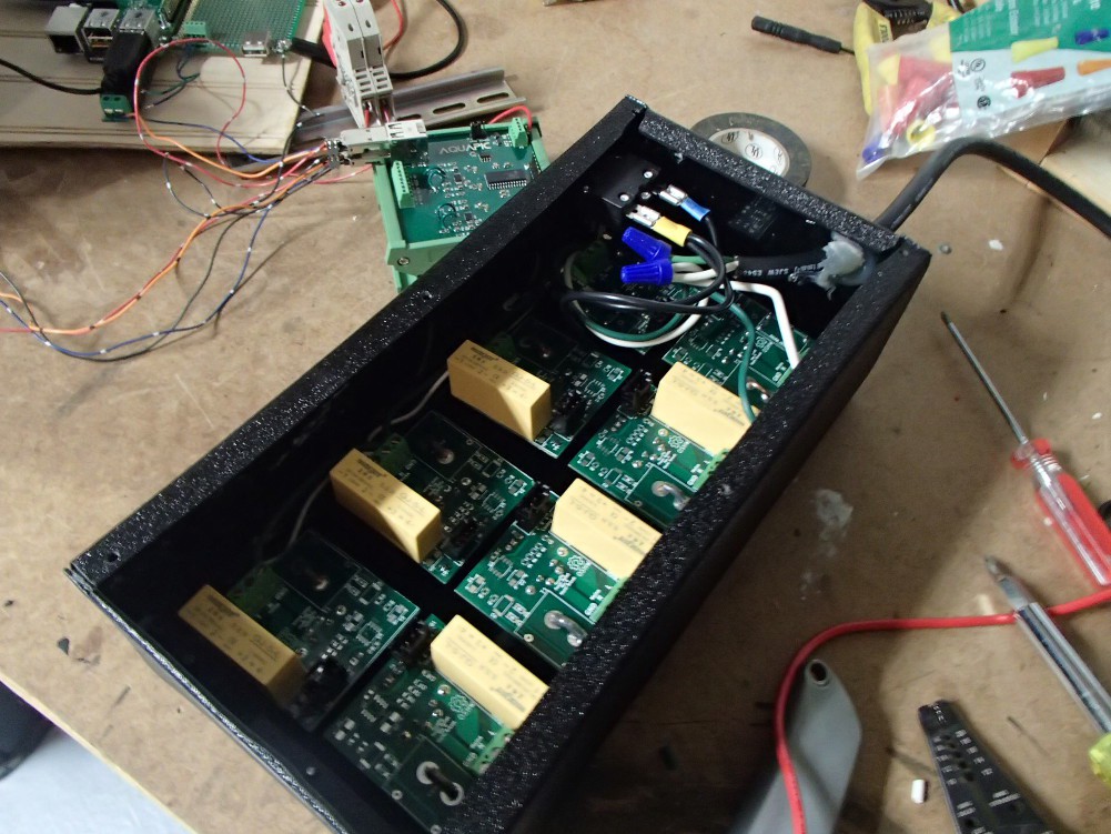
I still need to figure out how to show the status, power, and AC power available (currently not wired up) LEDs on the outside of the enclosure. This will also probably require relocating the LEDs to somewhere else on the control board or to a separate LED board. Also, the power LED is soldered on backwards. Those are really hard to tell which end is the cathode or anode. Once all the control stuff was working. I moved onto the mains wiring.![]()
![]()
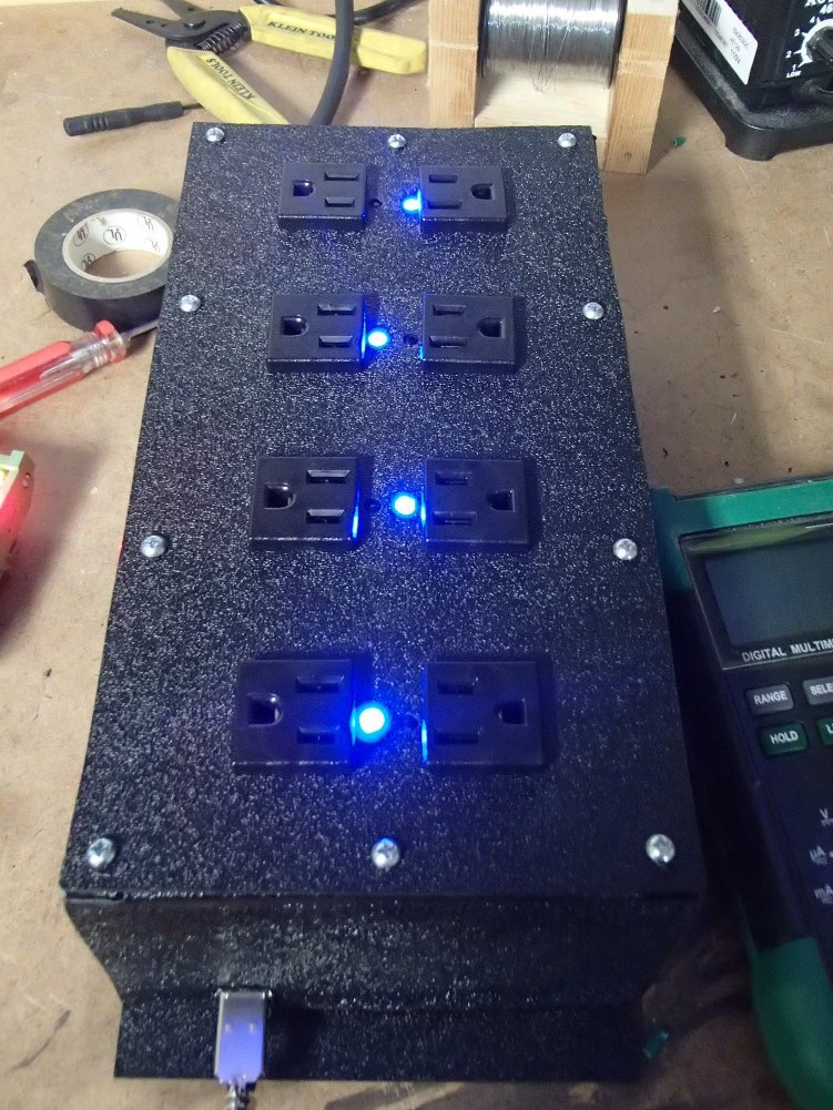
When I first built the enclosure I thought I made it a little too tall, but it proved to the perfect size after I shoved all the wires in there and screwed it together. And with it plugged into mains and hooked up to the controller, everything worked like it was supposed to.![]()
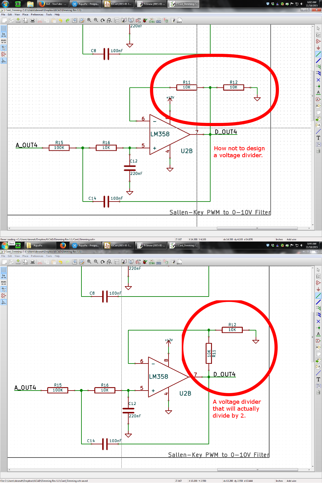
The dimming card gave me a little more trouble than the power strip. First, I complete screwed up the gain feedback for the filter opamp. The dimming card is supposed to take a 0-5Vdc PWM signal and turning it into 0-10Vdc constant voltage. However, I was only getting a filtered 0-5Vdc. Luckily, I found the issue fairly quickly. It's a pretty good indicator I did something wrong when the voltage on the inverting pin is the same as the output pin.![]()
I was able to fix the problem witj the existing board I already had, but it required cutting traces and soldering bodge wires. After I had that fixed though I still couldn't get the output to go all the way to 10Vdc. Whenever I went above ~55% duty cycle the output would automatically clamped to ~7Vdc and stayed there until around 35% duty cycle. This issue turned out to be the little switch IC I was using. My original plan was to have either 0-10Vdc or PWM output, and this switch would be used to software select between the two. However, this plan had several plan in it. First, the switch I was using is only rated for 5Vdc and its normally-opened pin is tied to the output of the opamp. So anytime the output of the opamp went above ~5.5Vdc, weird things happen inside that switch. Hence the weird voltage outputs. Second issue I ran into was that when switching the output to PWM that same normally-opened pin is still electrically connected to the opamp output, and subsequently two capacitors. So I was unintentionally RC filtering my PWM output. So I desoldered those little ICs and place a blob of solder over the old common and normally-closed pad, ensuring this dimming board only does 0-10Vdc.![]()
![]()
The last bit of progress was that I added a WiFi dongle to the RPi. I thought I would have to write a little script to get the time from a NTP server on boot, but the RPi automatically does this when it has internet. That was a nice surprise. Now the only thing holding me back from implementing this on my tank is some communication cable. I'm using regular USB cable but it is ridiculously hard to find plain USB cable without ends. So I ordered long pre-made USB cables and I'm going to chop them up into the lengths I need. I also need to clean up the inside of my tank cabinet so I have a nice place mount everything and make it pretty.
AquaPic - Aquarium Controller
Reef tank controller used to monitor various parameters such as temp and pH, and also control equipment such as pump and lights.

 I've been making good use of my free time though by making the user interface pretty.
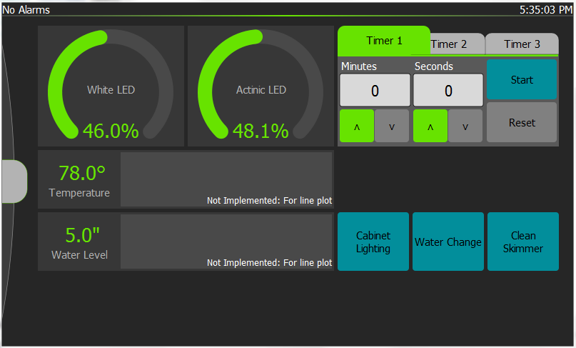
 The little boost DC-DC converter fixed all my low voltage issues for the RPi and touchscreen. I was surprised that was such an easy fix. Getting a MOSFET paralleled with the backlight controls on the touchscreen was not and turned out to be a bit more involved than I expected. Most of the difficulty was self induced though. The best solution I could come up with for bodging a SMD SOT-23 was three pads on a SOIC breakout board. It was ugly but it probably would have worked. However, problems arose when I referenced the MOSFET and driver circuit off neutral of the power supply I would normally use but then powered the RPi from a different power source. I didn't catch my mistake at first, and instead concluded that my bastardized SMD work was the culprit. So I ordered a proper through-hole FET and once again it didn't work. That was when I finally realized my mistake, switched my power to the correctly referenced source, and everything worked as expected. Now when the screensaver come on, the backlight turns off and then when I touch the screen the screensaver goes off and the backlight switches on. I designed the gate circuit a little different than most other p-channel gate control. The gate is normally connected to ground though a resistor. Then a transistor is placed on the high side to pull the gate up and shut the MOSFET off. That way while the RPi is booting or something happens to the script that controls the GPIO, the backlight will fail on.