Skyler Brandt
-
November 23, 2015
11/25/2015 at 21:59 • 0 commentsThis is going to be a short post, but I need to rant. In my opinion, Mono is really well implemented. They do a good job throw not implemented exceptions when the code isn't implemented under it's framework. However, they completely missed the fact that mark/space parity is not implemented in MonoPosixHelper.dll. My RS485 communication doesn't work on the Raspberry Pi but does under Windows. Luckily I started down the right path, think that 9th address bit, aka parity, was my issue. I had to dig all the way down into the C code to find this gem:
case Mark: /* Mark */
    /* XXX unhandled */
    break;
case Space: /* Space */
    /* XXX unhandled */
    break;
I don't care that these aren't implemented. I would not be surprised if I'm one of the first, if not the first person, to run into this issue. I'm just wish that would have thrown an error telling me, "Hey, mark and space aren't implemented, do something else". Now the question is, do I change that in C code and recompile Mono, or just hack around it with setting Odd/Even every single sent byte. -
October 8, 2015
10/08/2015 at 23:23 • 0 commentsThis week I worked out a few more of the bugs with the reflow oven and solder paste dispenser, build a box for the Raspberry Pi and touchscreen, and assembled the power control board.
After watching a few videos of other people's reflow ovens, I noticed that they had a thermal mass connected to the end of the thermocouple. Mine was only floating in free air so that would have thrown off the readings because it doesn't accurately show what the temperature of the part I would be trying to reflow. To implement a thermal mass, I simply stuck the end of the thermocouple though a hole on a protoboard.
![]()
This also fixed the problem of the ugly wire to keep the thermocouple suspended in air. However, the thermal mass complete throw off my PID tuning, so I had to redo that. It went a lot smoother the second time around, and I'm much happier with the results.
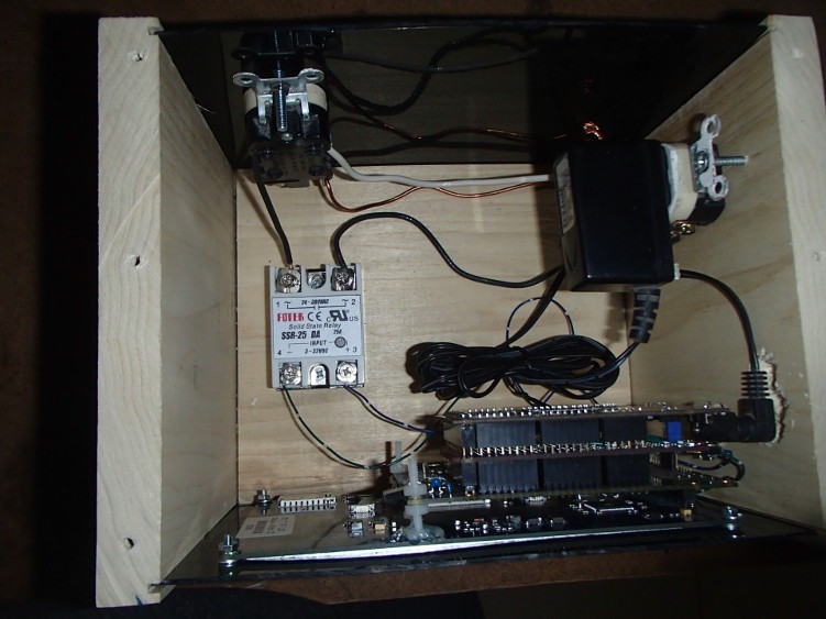
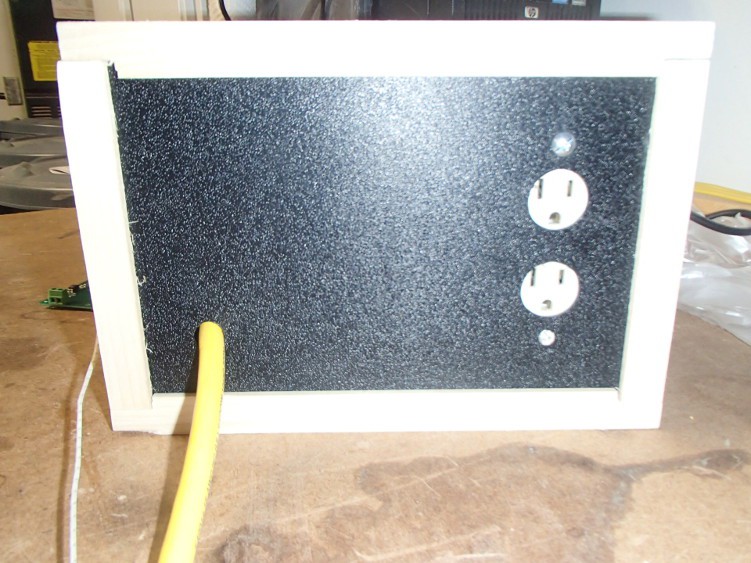
![]() As promised in my last post here are the pictures of the inside (and back) of the reflow oven.
As promised in my last post here are the pictures of the inside (and back) of the reflow oven.![]()
![]()
![]() I also figured out my issue with my solder paste dispenser. The paste I ordered was a little dried out. Sparkfun has a video about revitalizing solder paste and its simply stirring in flux until the consistency looks right. That made all the difference in the world though. I was able to use the really small, 26ga, needles and work with the small pitch parts, ie TQFP, with ease.
I also figured out my issue with my solder paste dispenser. The paste I ordered was a little dried out. Sparkfun has a video about revitalizing solder paste and its simply stirring in flux until the consistency looks right. That made all the difference in the world though. I was able to use the really small, 26ga, needles and work with the small pitch parts, ie TQFP, with ease.![]()
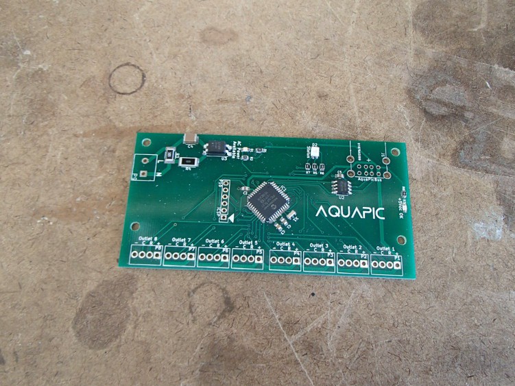
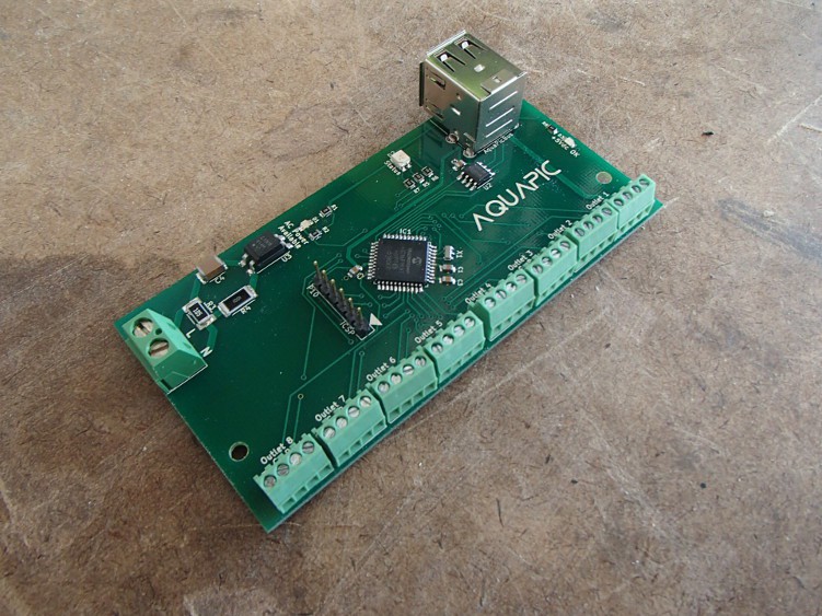
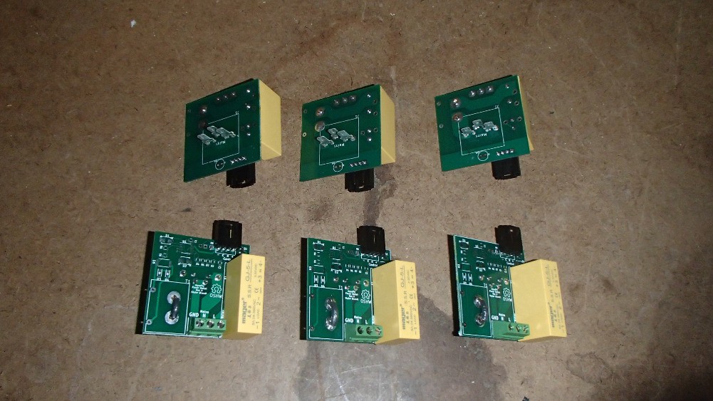
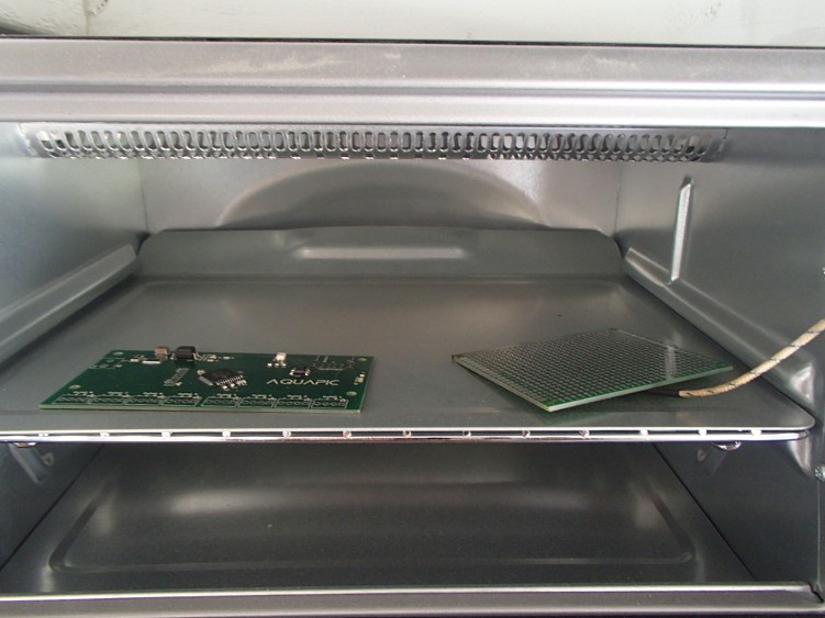
The above picture is a power control board ready to be reflowed, and below are the finished product. I haven't had time to program and test the board to make sure everything works. Fingers crossed.
![]()
![]()
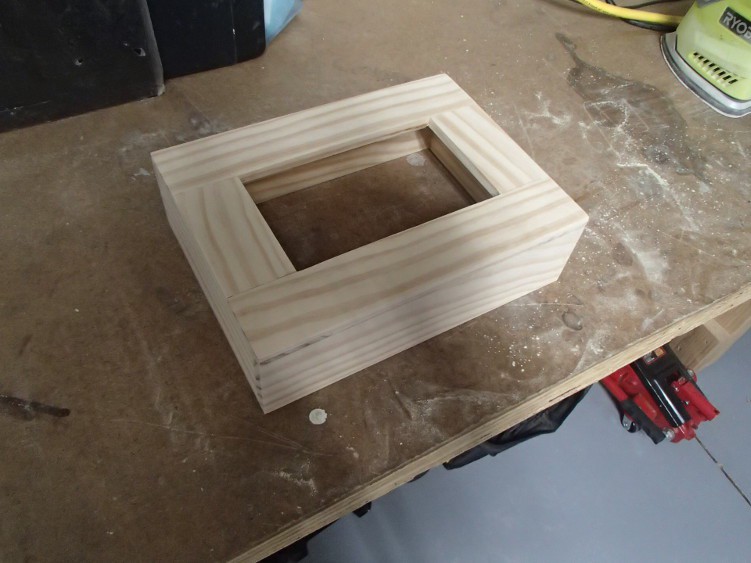
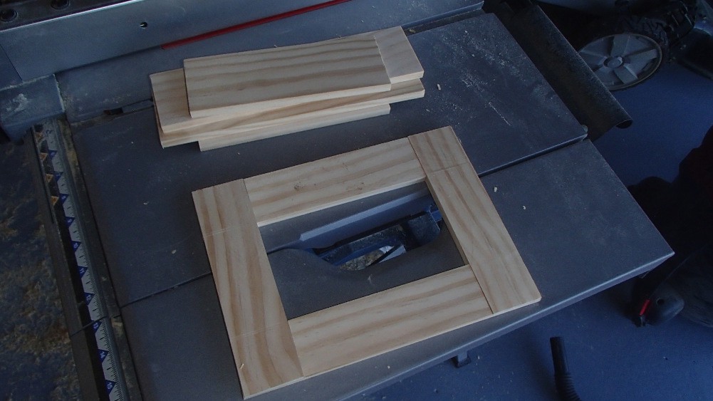
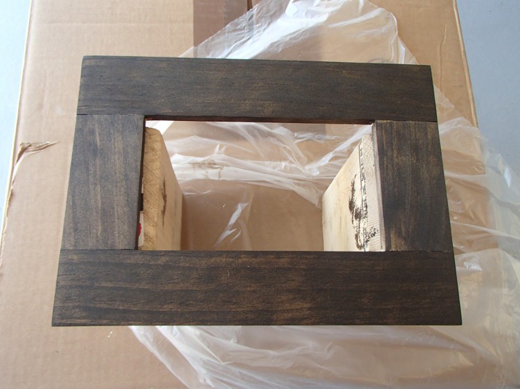
Finally, I built an enclosure/box for the Raspberry Pi and touchscreen. Its made out of pine ripped down to ~1.75" by 3/8". The front is joined by simple rabbet joints and the sides are straight glued.
![]()
![]()
I've strained everything a nice dark finish, but haven't applied a clear coat yet.
![]()
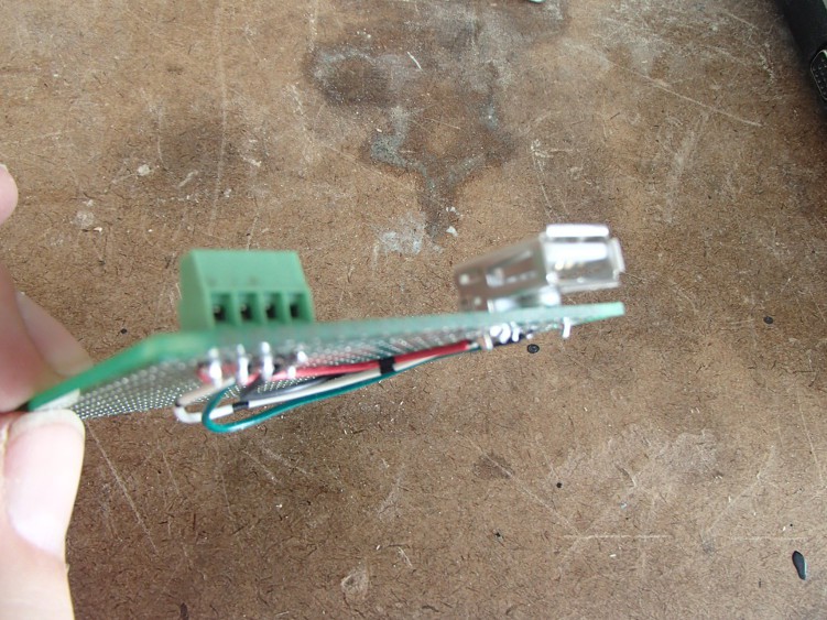
I made a "breakout" board for the communication, AquaPic Bus, and power. The AquaPic Bus is a RS485 protocol I wrote. I'm using a USB to RS485 dongle on the RPi, because it was a lot easier than using the UART pins on the GPIO and then having to level shift from RPi's 3.3V to 5V.
![]()
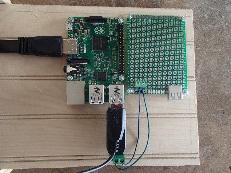
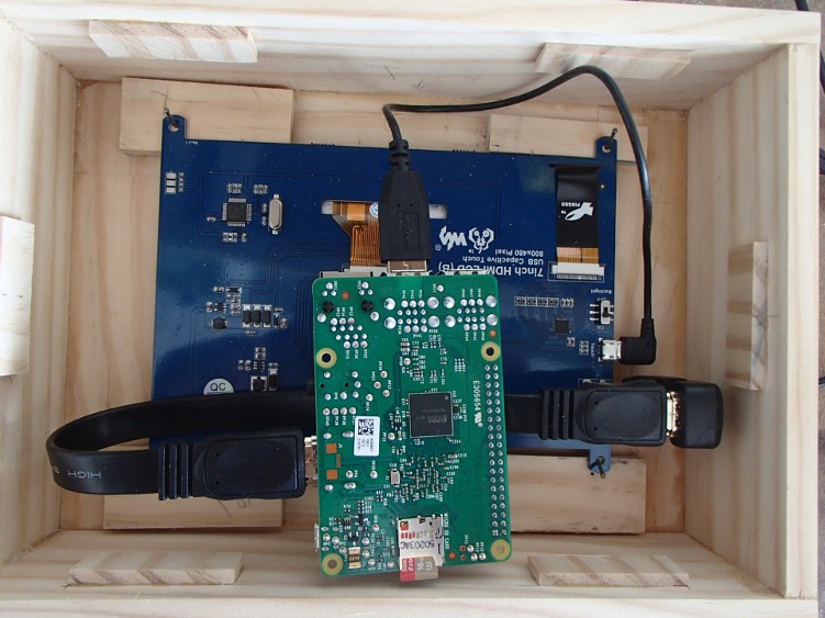
I then attached the "breakout" board and the RPi to the enclosure backing, and did a little wiring. I'm going to make a short jumper cable between the power on the screw connector with a micro USB connector on the other end to power up the RPi. The 5V for this will come from the same power supply as the rest of the cards.
![]()
![]()
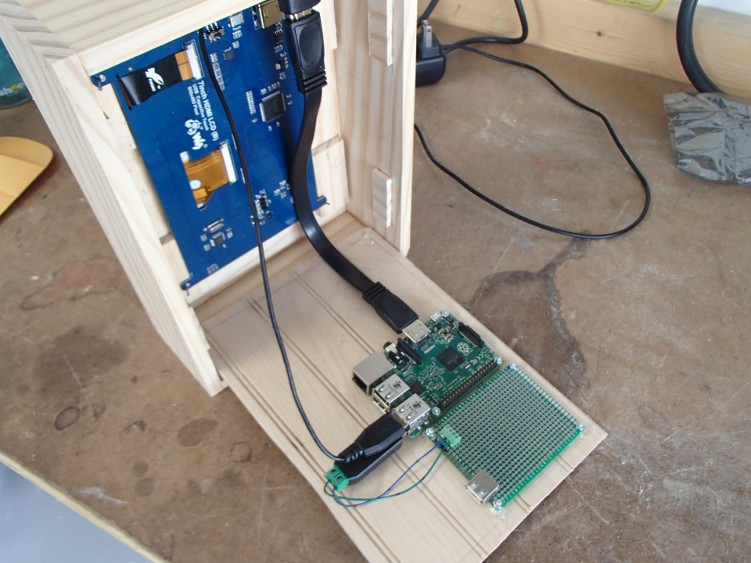
This is the inside of the box and how the RPi will be positioned when the back is in place.
![]()
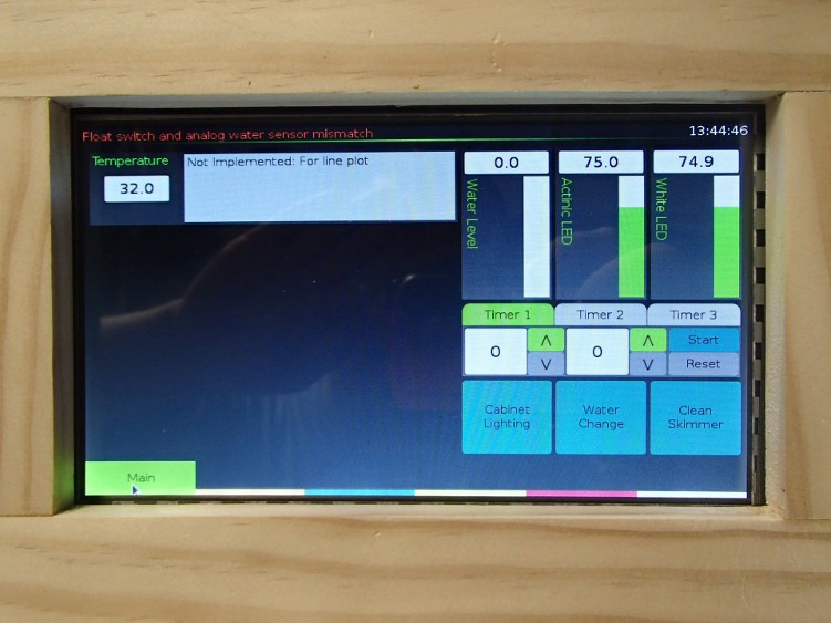
Before I starting staining the box I had to power up everything and make sure it worked.
![]()
-
October 1, 2015
10/01/2015 at 07:39 • 0 commentsI finished up that last 20% on a few of my projects the last few days. The solder paste dispenser and reflow oven are finished. Neither is particularly polished, but both work good enough.
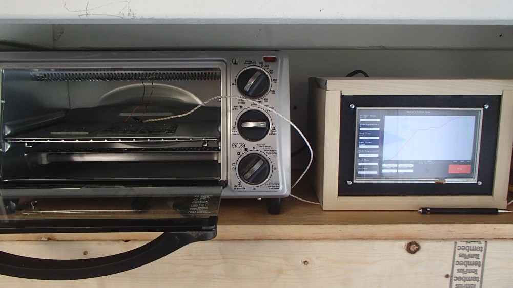
The reflow oven is really rough around the edges, and all around a poor excuse for programming and hardware design. I did uploaded the code to GitHub though. The design is really simple though. Like a said in an early post, I used the chipKit Max32 and a touchscreen I purchased previously for the AquaPic. I also had a protoboard shield for the Max32 that I soldered the thermocouple amplifier board and MOSFET that fires the relay to. I didn't do any modification to the actual oven. I simply set everything to max and plugged it into an outlet that is controlled by a relay and the controller. Below is a picture of the overall setup. I still need to snap some picture of the inside of the controller enclosure.
![]()
I had one hell of a time tuning the PID loop. I originally had the update for the PID loop set to 1 second but that ended up being too fast. I slow it down to 5 seconds and that seems to work a lot better. Temperature is a slow process. If I hadn't spent a bunch time researching and learning PID process control, I would have just simply used a "fast", 100-500 ms, proportional control scheme.
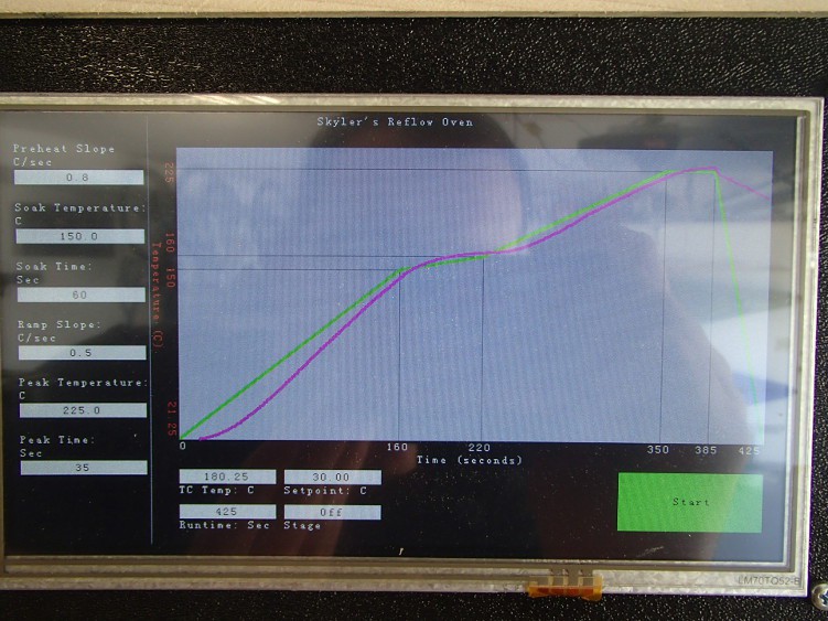
There are lots of little bugs and quirks with this oven. First, even though I spend a lot of time tuning the PID loop, its not the best at regulating temperature. My biggest issue is the overshoot at peak temp. Below is a picture of one of the reflow cycles. Its kind of hard to see, but the green line is the setpoint and the pink line is the actual temperature. The oven takes a little bit to build up heat so that why the preheat stage doesn't follow. It's obviously better if the preheat slope is set to 1.0 C/sec.
![]()
Secondly, the thermocouple amplifier doesn't isolate the thermocouple or something, and if the thermocouple tip is touching anything grounded, it pulls the entire +3.3V control rail to ground. At least to the best of my knowledge. Another issue is that occasionally when the computer is connected to the chipKit and the oven is running, the LCD screen goes all weird. Not sure why that happens but its not a concern since I never run this with a PC hooked up. Lastly, the oven goes to "Off" after the peak is reached instead of cooldown. Its not a big deal except the graph is only updated while the oven is running. I did make a few changes to the GUI that are not reflected in the above picture. The PID gain text box has been removed, and the graph's Y-axis is a little bit bigger so to show the overshoot at peak.
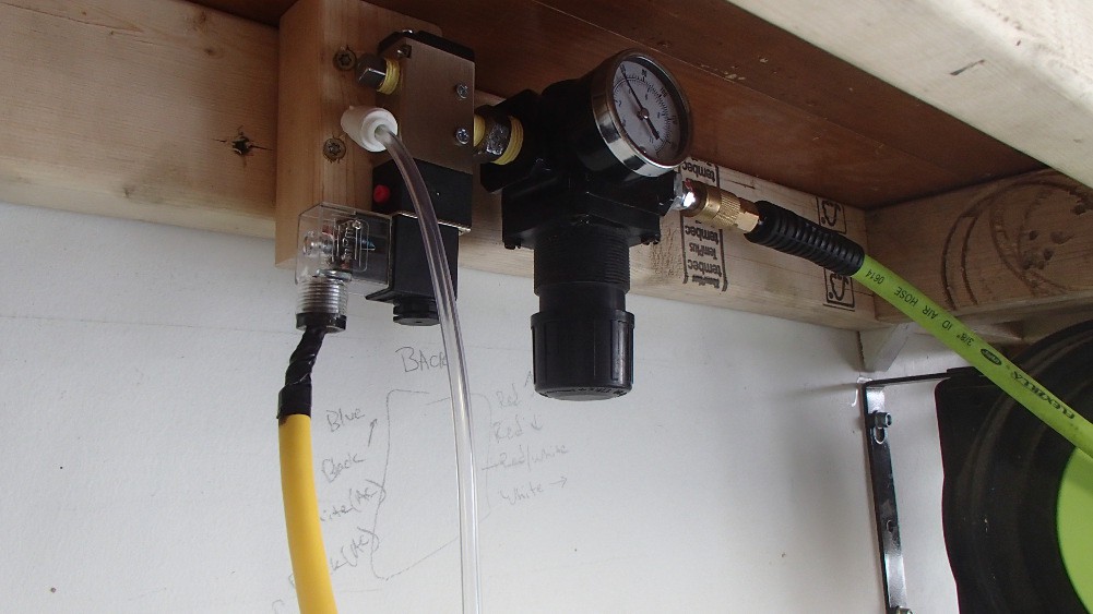
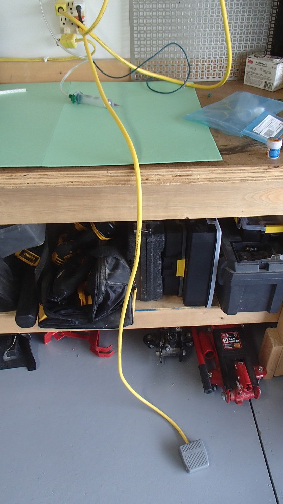
The solder paste dispenser actually turned out decent. Really the only issue I had was related to needle sizing. It takes a lot of pressure to push solder paste though some of the smaller needles. I still have some playing around to do before I figure out the perfect pressure/needle size combo to achieve the desired bead of solder. The dedicated pressure regulator I added made adjusting air pressure a breeze. Wiring everything up was straightforward. Its all 110Vac so I just run the hot through the foot pedal and back to the coil on the valve. The actual switch inside the foot pedal is a little wimpy and I'm guessing that is going to be the first point of failure. The cheap valve is working out though. I wasn't sure if it would shift fast enough for this application but it seems to be fine.
![]()
![]()
With a working solder paste dispenser and reflow oven, I was able to start assembling some boards. Well actually, just 6 copies of one board, the power outlet. For this first prototype I'm not including current sensing so there was only two smd components, a MOSFET and a resister. There actually should have been three smd parts but I forgot to order the flyback protection diodes. This isn't required for the outlets that will be controlled by a solid state relay, i.e. the 6 boards I already assembled. However, it will be required for the 2 outlets with mechanical relays. The rest of the parts on the outlet board were all through-hole and hand soldered. Below is how the outlet board and socket will go together. The outlet socket will be attached to the enclosure then the board's stabs will be inserted into the socket and left sort of free hanging.
![]()
Finished product so far:
![]()
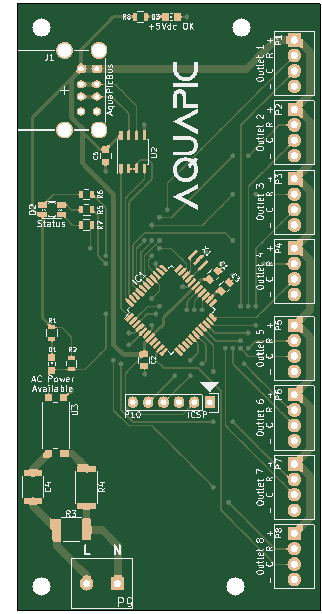
During assembly of the outlet board I noticed an issue with it. I forgot to include a pull-down resister to the gate of the MOSFET. This won't be an issue when the outlet board is connected to a driven microcontroller pin. However, if the outlet board isn't connected to the control board or the control board isn't power up, the state of the MOSFET and therefore the relay will be unknown.
-
September 20, 2015
09/20/2015 at 09:21 • 0 commentsThis blog post is going to be a bit scattered. At this moment, I have a lot of projects at the 80% or a little more done, but nothing complete finished. I have been putting off any sort of update because I've been waiting to at least finish one or two of the items I have out there. However, its just taking a little longer to complete anything than I originally expected, as usual. However, I decided that I've accomplished so much this last month that I should share it and not worry about the last 20%. It will be completed soon. Last disclaimer: there will also be a severe lack of pictures or video in the post simply because I haven't taken the time to document anything.
On to the good news. I'm officially saying that the main software application for the controller is in beta. I'm really happy with the state that it is in, and would have no problem letting it run the tank. Next, I went on a shopping spree a little over a month ago and hopefully have all the parts and pieces needed to complete the main unit, a dimming (analog output) card, and a power strip. One of the items I order was a touchscreen for the Raspberry Pi, and its working out pretty good so fair. I did however have one hell of a time getting my program to run in "kiosk mode". I can't remember all the hops I tried to jump through, but there was lots of moving when and where the script that starts my application is called. Long story short, Gtk needs X10 to already be running before it will work. I'll have to make a short post about where that's called from because I couldn't find any good examples or help on the internet.
In addition the the controller stuff, I also order parts to build myself a solder paste dispenser and to finish my reflow oven. I based my solder paste dispenser on Sparky's Widgets design with a few changes. First, I didn't see any reason to use a microcontroller. Voltage is instead applied to the coil of the control valve with a simple foot switch. I'm also using a slightly different control valve. This one is more of an "industrial" valve with a 110Vac coil. Its a 5 way valve which isn't required, but it was cheaper than the 3 way valve. The 'A' port is plugged and the 'B' port is used to apply pressure to the syringe. Lastly, my air compressor's regulator sucks at reducing pressure less than 50ish lbs. Luckily I had a really nice one sitting around. I plumbed that into the system and it provides reliable low pressure to the system, down to around 10lbs. It works lower than that but at that pressure the valve start to have issues operating. I haven't tested the dispenser with solder paste yet so it might not even work, but dry runs work properly. One of the issues I'm worried about is the valve being to slow for this application.The reflow oven is darn close to being finished as well. I used the chipkit Max32 and touchscreen I originally purchased for the AquaPic to control the oven. All the firmware is done for that and works. I also built an enclosure for the control circuitry. The only thing that remains unfinished is tuning the PID loop, which I'm almost done with as well. Once the PID loop is tuned, I can start populating and reflowing the boards for the controller. I need to build some sort of enclosure for the power strip, but I have a pretty good plan to move forward with that. I however have no idea what I'm going to do for the RPi and its touchscreen. Lastly, the firmware for the slave modules is coming along nicely.
-
August 8, 2015
08/14/2015 at 12:15 • 0 commentsI've ordered my first batch of boards. The dimming, and power strips PCBs are on the way from someplace in China. I went as cheap as possible so they'll take a little bit to get here. In the mean time, I've written an application the combines all my build material excel files into one master list. Right now I'm just doing silly little things on the project as I wait to slowly buy things.
Edit:Apparently some PCB manufactures don't like when you pre-panelize a gerber file and will charge a "fee" in such occurrences. I was dinged with an extra $15 because the Power Outlet PCB was four copies on one board. The middle man I went though was really helpful though. He said that if I ever need to do that again, that he has another factory that will accept panelized PCB's for just a little extra. They will also cut out each board.
-
August 3, 2015
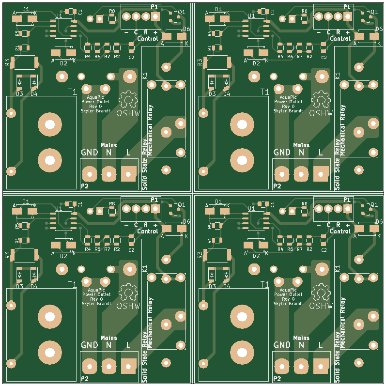
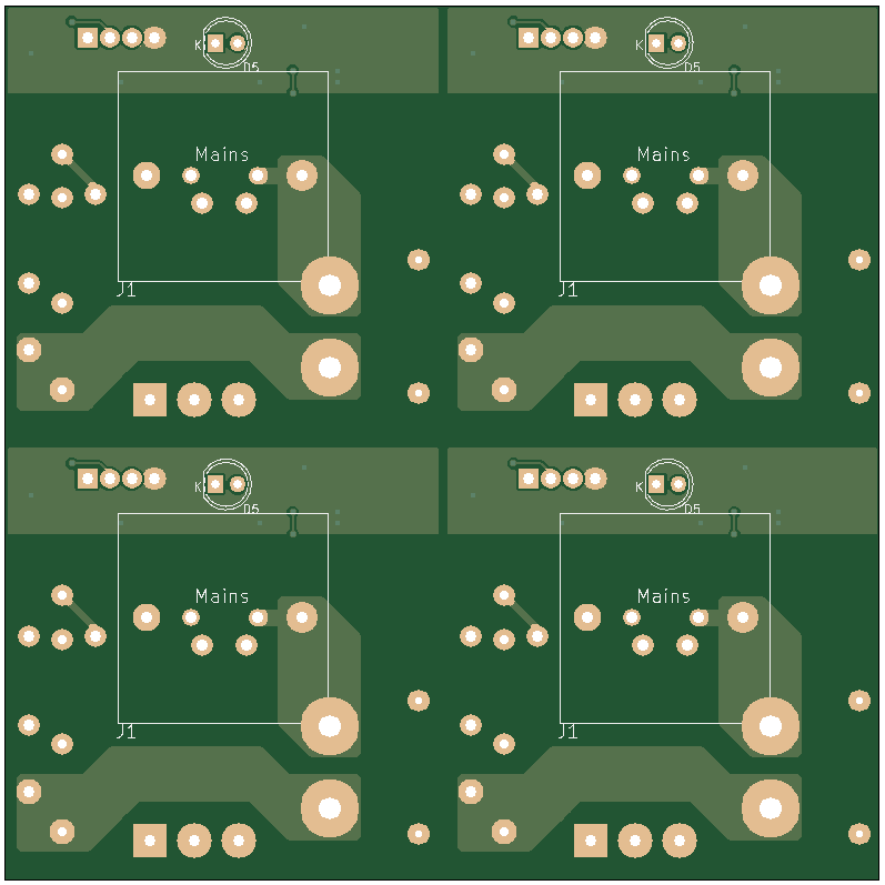
08/03/2015 at 17:10 • 0 commentsI finished layout out the two boards for the power strip, control and outlet. I "panelized" the outlet boards and place 4 on each 10x10xm PCB. Its more economical because from what I've found, most PCB manufactures only change a few extra dollars for a 10x10cm boards vs a 5x5cm board. I also found a great price comparison website for cheap board manufactures, PCB Shopper. I've also been doing quite a bit of searching for an enclosure I like for the power strip but I haven't found anything I like. My ideal enclosure would be around 250x120mm but most boxes fairly square-ish. I think I'm just going to get some acrylic and make my own box.
![]()
![]()
![]()
![]()
-
July 31, 2015
08/03/2015 at 17:02 • 0 commentsI decided I'm not going to do a backplane or anything like that because its just extra money. I'm just going to use DIN rail PCB mounts for each of the cards, because I think that will be the simplest solution. Luckily I only had one card laid out, Dimming, which required a redesign. When I started relaying out the board I thought I could just move a couple things around but I ended up deleting everything and starting over. Most of the reason for this was I finally updated KiCAD and its has some fairly substantial changes since I last updated it, mostly to the way it handle footprints. This is what the board should look like now:
![]()
![]()
-
July 29, 2015
08/03/2015 at 16:00 • 0 commentsThis week has been a very productive week for me. I ordered a USB to RS485 converter, so I was able to fully test my communication protocol. I also started testing the dimming card firmware. I had to make a small change to the way a slave module talks because the RS485 transceiver chips I'm using have a transmit and receive enable pins, which requires an extra output on the microcontroller. The extra pin is set high to enable transmit and low to enable receive. This is the first issue I ran into. Originally my write function looked like this.
void writeUartData (uint8_t* data, uint8_t length) {
    TX_nRX = 1; //RS-485 chip transmit enable is high

    int i;
    for (i = 0; i < length; ++i) {
        TXREG = *data;
        ++data;
        while (!TXIF) //TXIF is set when the TXREG is empty
            continue;
    }

    TX_nRX = 0; //RS-485 chip receive enable is low
}
As the comment says the TXIF, transmit interrupt flag, is set when the TXREG is empty. My oversight was the the TXREG is moved into the transmit shift register before it is sent, so just because the TXREG is empty doesn't mean that the message has been sent. I was disabling the transmit of the transceiver chip before the last byte was sent. All I had to do to remedy that bug was after the for loop wait for the transmit shift register to be empty before setting the transmit/receive output pin low.while (!TRMT) //wait for transmit shift register to be empty continue;This issue was made harder to diagnosis because I was using a buggy version of MPLabX to debug the program. MPLabX V2.05 has an issue with loading the PICKit3PlatformTool module. That failed module would cause the Debugger to not halt the program on my breakpoints most of the time. That issue lead me down the wrong troubleshooting path and I subsequently spend a while chasing a red herring. I finally paid attention to the error and warning messages I was getting during the application launch and saw the warning about the PICKit3PlatformTool not working. After I uninstalled V2.05 and installed the latest, V3.05, the Debugger worked as it was supposed to, and I was able to properly diagnosis the problem.
The next bug I ran into was the way C# handles the size of structs.
public struct CommValueInt {
    public byte channel;
    public short value;
}
The above struct is apparently 4 bytes in size instead of what I think should be 3 bytes. C# pads a byte between channel and value, so when I was dissecting the message in the slave I was one byte off from the start of the value variable. I might have manual construct a byte array for each message so I have better control of the size of the message.The last issue I had to overcome was the PWM filter. The output voltage was all over and sporadic. That just boiled down to a resister not being pushed all the way into breadboard.
-
July 24, 2015
07/24/2015 at 19:38 • 0 commentsHere is just a quick video update of the current status of the project and to show what I've been working on for the past while.
-
January 27, 2015
02/14/2015 at 00:55 • 0 commentsI have successfully made the changes I wanted to make to the serial communication protocol after a lot of pain, frustration, confusion, screaming, yelling, headache, and about 8 hours of my time. The way the protocol works now is messages are queued up, FIFO stack, and then a separate thread dequeues the top message and sends that to the slave. It then calls a callback function if a response beyond the generic response is received. I also added a byte count to the message to indicate length. I almost did a complete re-write of the master code and a few small changes to the slave, so it inevitable didn't work right off the bat. There were a few run-time errors but the most frustrating one and the bug that gave me the most grief was due to a forgotten break keyword in a switch statement.
case FUNCTION_RECIEVED:
    inst->message_length = byte_received;
    inst->message[2] = inst->message_length;
    inst->message_count = 3;
    inst->apb_status = MESSAGE_LENGTH_RECIEVED;
    break; // <----- 8 hours of my life I'll never see back
case MESSAGE_LENGTH_RECIEVED:
    inst->message[inst->message_count++] = byte_received;
    if (inst->message_count == inst->message_length) {
        if (apb_check_crc(inst->message, inst->message_count)) {
            inst->message_handler();
        }
        //more processing
    }
In the code segment the switch statement is switched by status of the message, and case FUNCTION_RECIEVED basically falls into case MESSAGE_LENGTH_RECEIVED. That resulted in inst->message[2] and inst->message[3] to be the same value and the crc check would fail. The slave would then think the communication was faulted and never send a response. That took me about 8 hours to find and so much headache. The other issues I ran into was threading related. The Gtk library crashes and does funny things if you call a function or update a property from a thread that didn't start the Gtk application. The fix for that was a Google search away, so that wasn't to bad to fix, and was as simple as calling an invoke to add a delegate to the event system of the Gtk run time.Full code at my build log.
AquaPic - Aquarium Controller
Reef tank controller used to monitor various parameters such as temp and pH, and also control equipment such as pump and lights.
 As promised in my last post here are the pictures of the inside (and back) of the reflow oven.
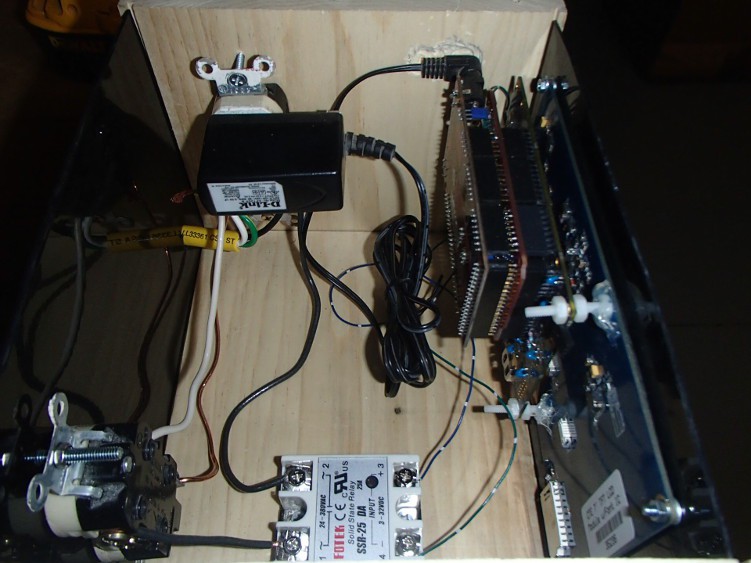
 I also figured out my issue with my solder paste dispenser. The paste I ordered was a little dried out. Sparkfun has a video about revitalizing solder paste and its simply stirring in flux until the consistency looks right. That made all the difference in the world though. I was able to use the really small, 26ga, needles and work with the small pitch parts, ie TQFP, with ease.