Philip Ian Haasnoot
-
The TOME Status
02/03/2016 at 21:46 • 0 commentsFirst off I would like to thank everyone for the continued interest in this project, to give a brief update on the project:
The TOME team had to put this project on the back burner to focus on other ventures. This summer we will be re-launching the project with the goal of producing the first fully-functional prototype and doing some real world testing. Keep your eyes peeled for updates!
-
Out of the Running
09/30/2014 at 23:59 • 1 commentIt was with great sadness that Corey and I had to shift our focus away from the Tome to more pressing matters, as the deadline for the second video approached we tried our best to shift working schedules and find time to produce updates but ultimately were unable. We are still going to update the project as time allows, and will hopefully get the TOME to production one day.
Thank you for all of the support and interest, we hope that you will all continue to follow our development into the future.
-
3D printing and GrabCAD
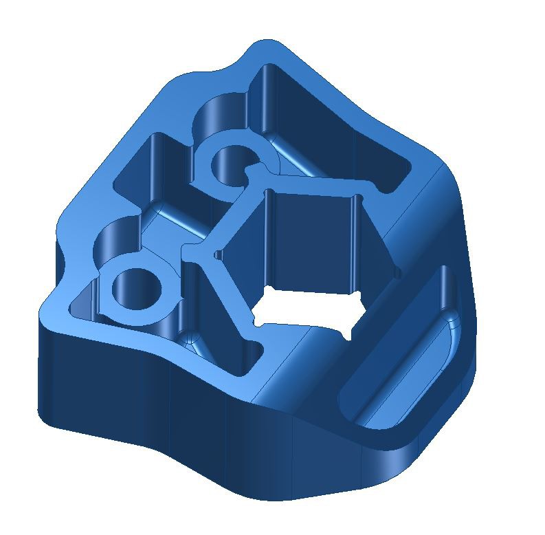
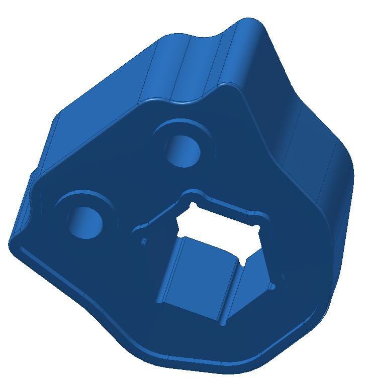
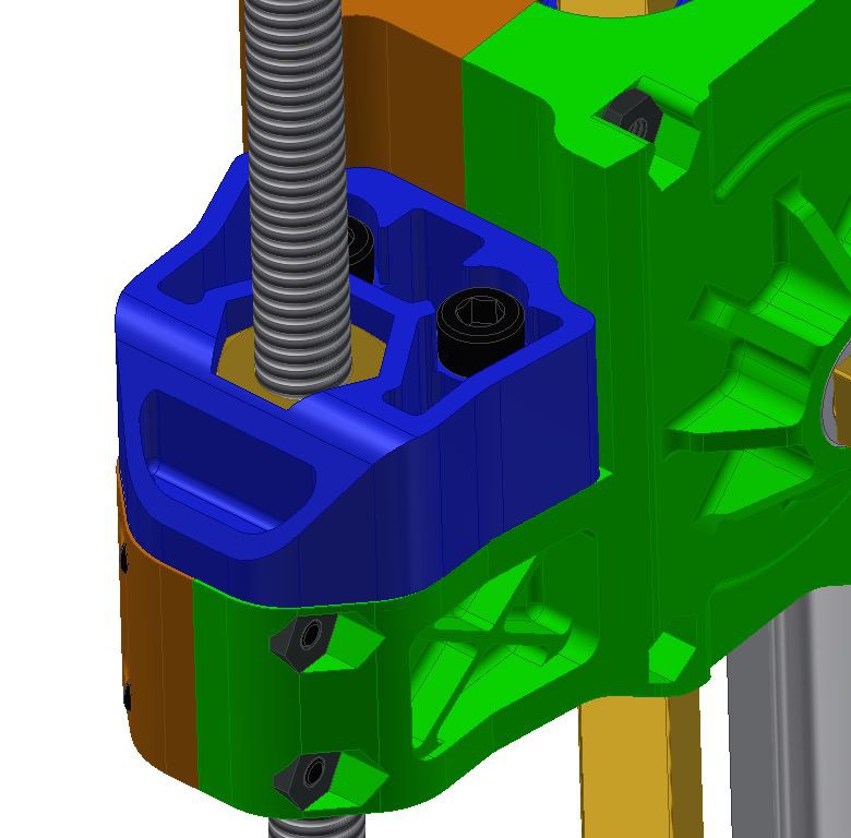
09/18/2014 at 06:20 • 0 commentsI was able to 3D print the nut retainers today and they came out great, still need to order the Shapeways parts to really put the entire assembly together. I'll be kicking that order off this Friday and will have enough components to get the Z-axis together and operational. I'll keep plugging away at the design for the X and Y axis but wont be able to get parts in for those until after this second round of judging.
I also took a moment to update the GrabCad project located here: https://grabcad.com/library/tome-3d-printer-1 with more finished components. Please note that these parts may change over the course of the design, and new versions will be marked V2 when I update the files.
![]()
![]()
![]()
-
Back in action
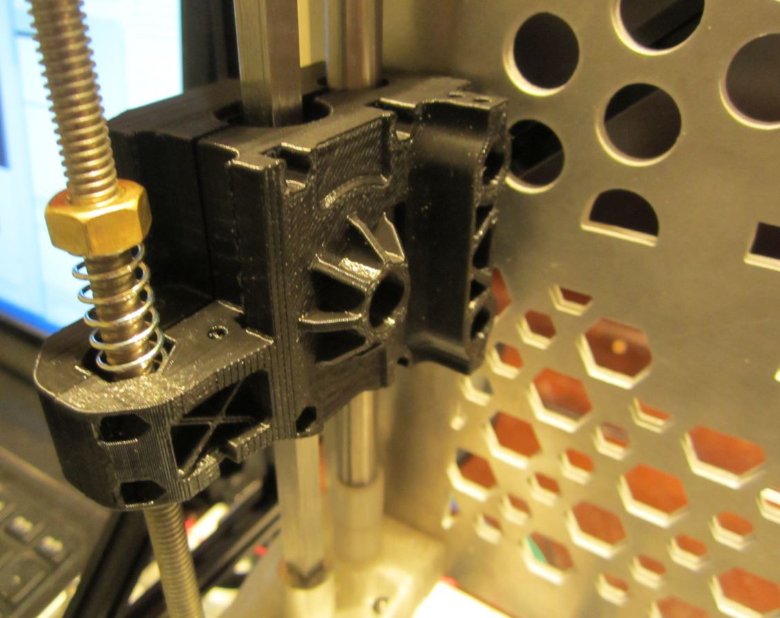
09/17/2014 at 06:09 • 0 commentsWith the looming deadline I have had to dramatically reorganize my schedule in order to continue working on the TOME. I hope to provide CAD design updates throughout the week. Tonight I worked on the Z-axis anti-backlash nut cover, tomorrow I hope to have Z-axis stage and the X-axis carriage finished on both sides, and will be clear to begin work on the Y-axis and the extruder later this week.
![]()
-
TOME Test Rig
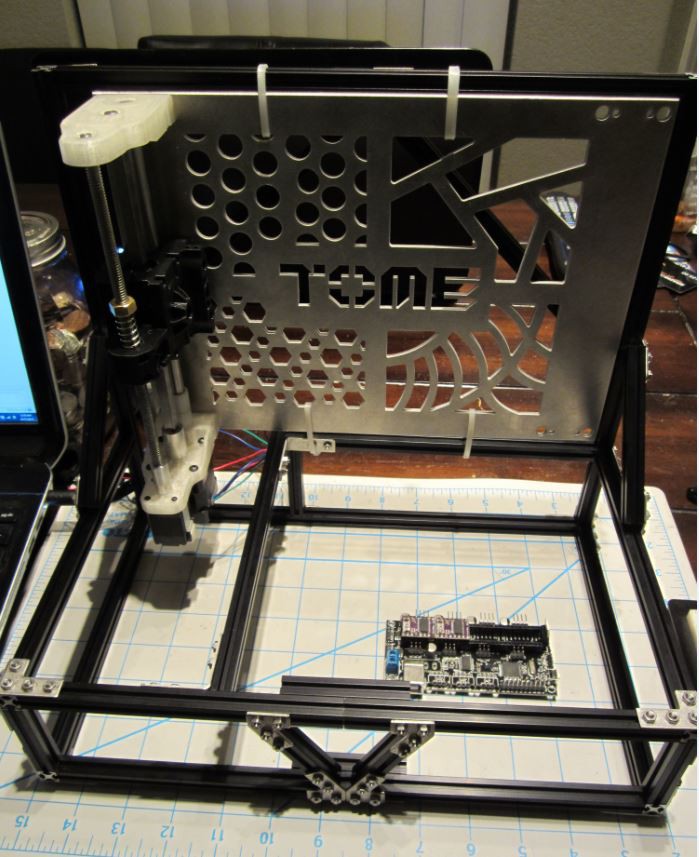
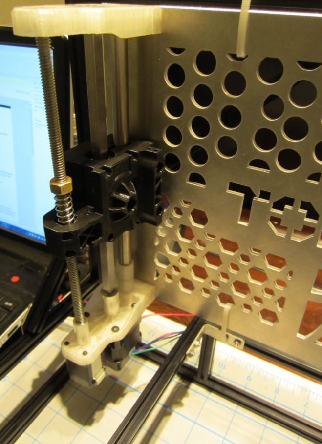
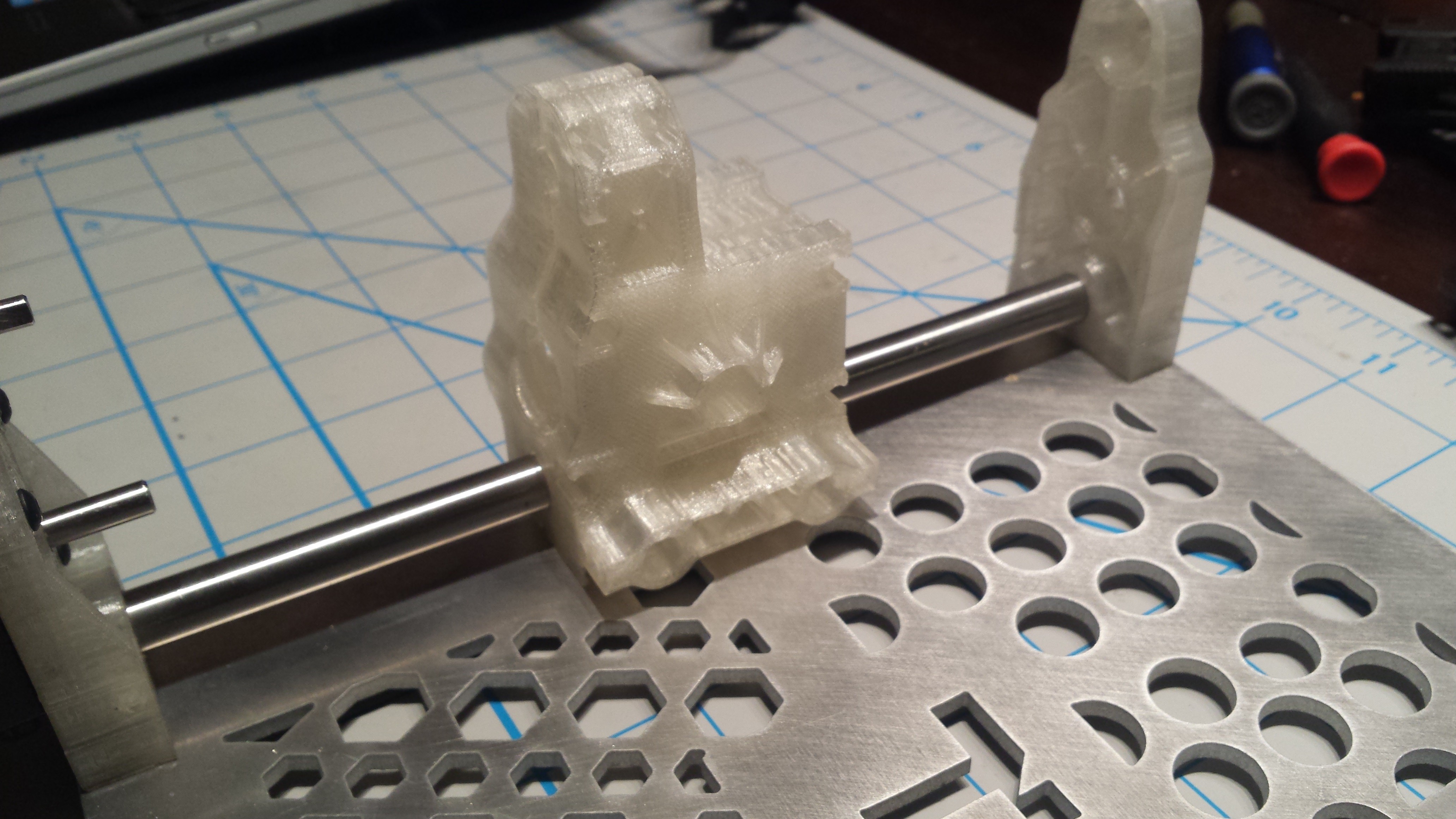
08/27/2014 at 08:31 • 0 commentsI was able to pull myself away from my other projects to give the TOME some love tonight. I've had this makerbeam sitting around for quite some time, generally I use it for quick test stands or supporting rigs for projects that i'm working on. The TOME rear plate will be re-cut in order to attach to the frame properly (Zip ties are temporary). I feel that attaching the backpane assembly to a rigid test fixture will enable us to perfect the mechanism and get great prints. Once we fine tune the motion mechanism we will make the TOME fold, this will help narrow down causality if our print quality degrades once the folding mechanism is instituted.
![]()
![]()
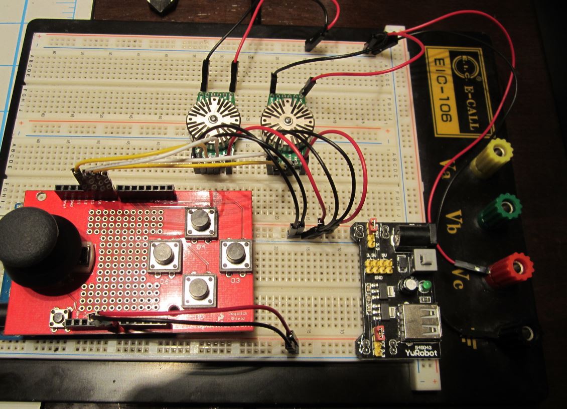
The StepperStack 2's arrived today and are currently wired up on the test board below. We are using an Arduino Uno, with a spare Joystick breakout from Sparkfun to drive the StepperStack 2's. The goal is to have a very rudimentary drive setup just to test the mechanism, the first prototype will then transition over to the Sanguinololu once we are ready to start printing. The goal is to spin our own board for the first portable prototype, for now our effort needs to be focused on finishing the XYZ Drive mechanisms.
![]()
The FDM 3D printer we are using to prototype parts is printing everything undersize, and any hole is oblong making it tricky to get our parts to fit properly. We are discussing SLS printing with a local company here in AZ, if all goes well we will have more accurate parts to work with. Currently you can actuate the Z-axis carriage (with spindle installed) by turning the Z-axis lead screw, however due to tolerance issues caused by the 3D printer we are using we cannot spin the X-axis spindle just yet. I'm going to adjust the spindle model to give us some clearance just for this test print so we can get one half of the drive mechanism moving under power. Stay tuned!![]()
-
Stage 1 Video
08/20/2014 at 18:09 • 0 commentsHere is the first round video for the TOME, we're hoping to have much more to show soon and are working on this project as much as our schedules allow.
Stay tuned!
-
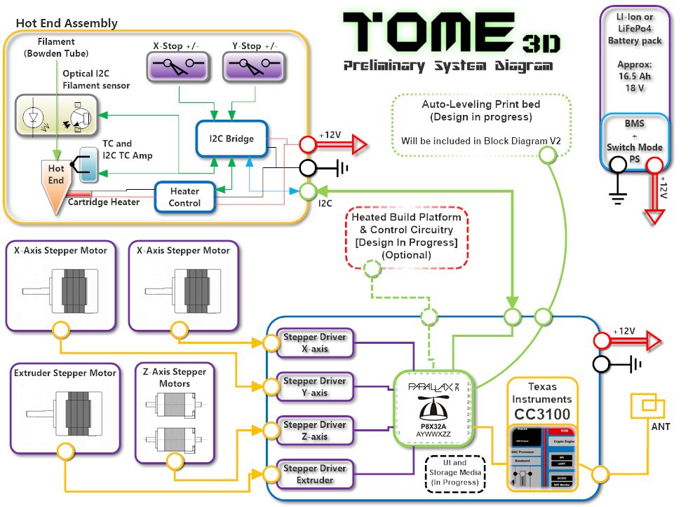
System Diagram V1
08/17/2014 at 21:40 • 0 commentsBelow is the preliminary system block diagram, I noticed a few mistakes once i uploaded it so I will update the diagram before the deadline on 8/20. Filming for the video wrapped up today and I will be making the necessary edits before uploading it to Youtube which will hopefully be done sometime Tomorrow night or Teusday afternoon.
![]()
-
Mind the Gap
08/11/2014 at 16:13 • 0 commentsI apologize for my lack of project updates for the past few weeks, several other projects have popped up in the meantime that needed my attention. Being this is essentially the last week to get our video together I will be focused on documenting the overall system architecture, and will be overhauling the project documentation to reflect where we are currently.
My estimated timeline
8/11 - System Architecture block diagram
8/12 - Electrical BOM for PCB (This will be a preliminary list)
8/13 - X-xis drive CAD model finalized
8/14 - X-axis drive design 3D printed
8/15 - Y-axis drive design completed
8/16 - Y-axis drive design 3D printed
8/17 - Prototype Assemble8/18 - Video shoot and editing
Unfortunately we will not have the funding to fully build the prototype by the video submission deadline, but will continue building up the prototype and will hopefully have a fully working prototype by November.
![]()
-
NEMA 14 issues
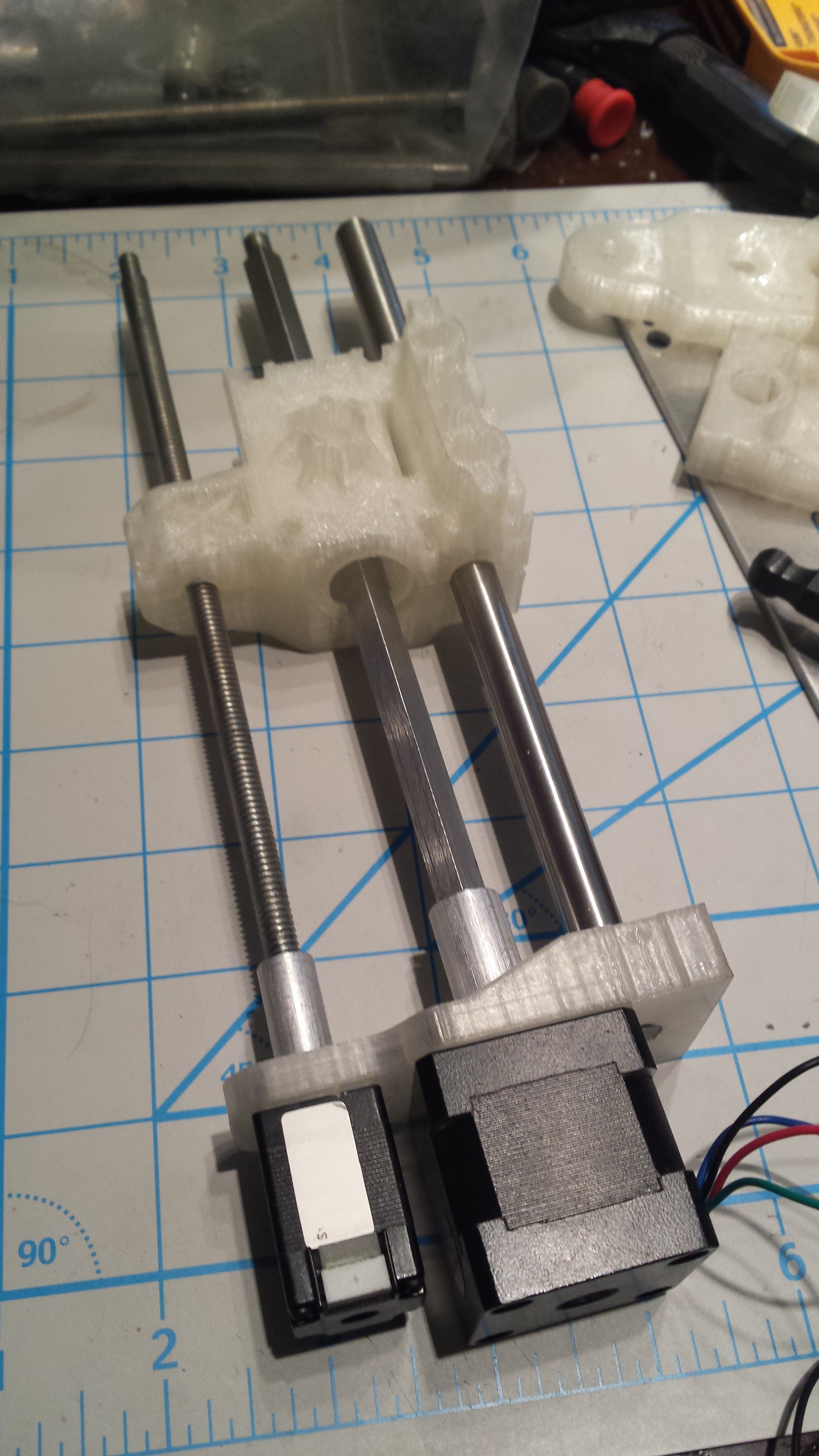
07/14/2014 at 05:22 • 0 commentsSo I worked on assembling one full side of the Z-axis today and ran into a few issues. The first is that our NEMA 14 steppers that were purchased from Pololu have a slightly longer shaft than the original batch from an alternative supplier. I should have measured them prior to any machining but didn't think to do so. The model has been updated to reflect the new shaft length, the only major change is that the X-axis square drive has a slightly shorter engagement with the coupler. Once the parts are modified I can install the last bearing and begin assembling the clamshell prototype.
![]()
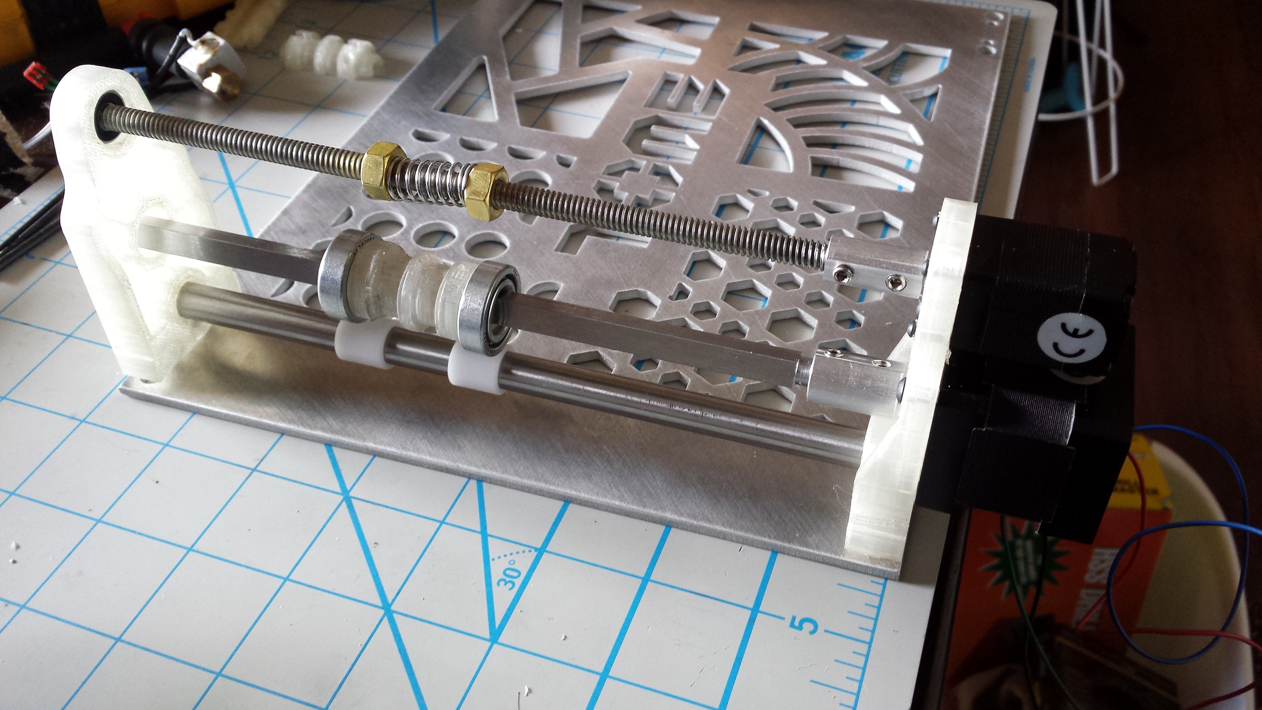
Here is the full assembly with the backpane, the top bearing mount appears to be floating in this image because I had not yet opened up the dowel pin locating holes to the right dimension.
![]()
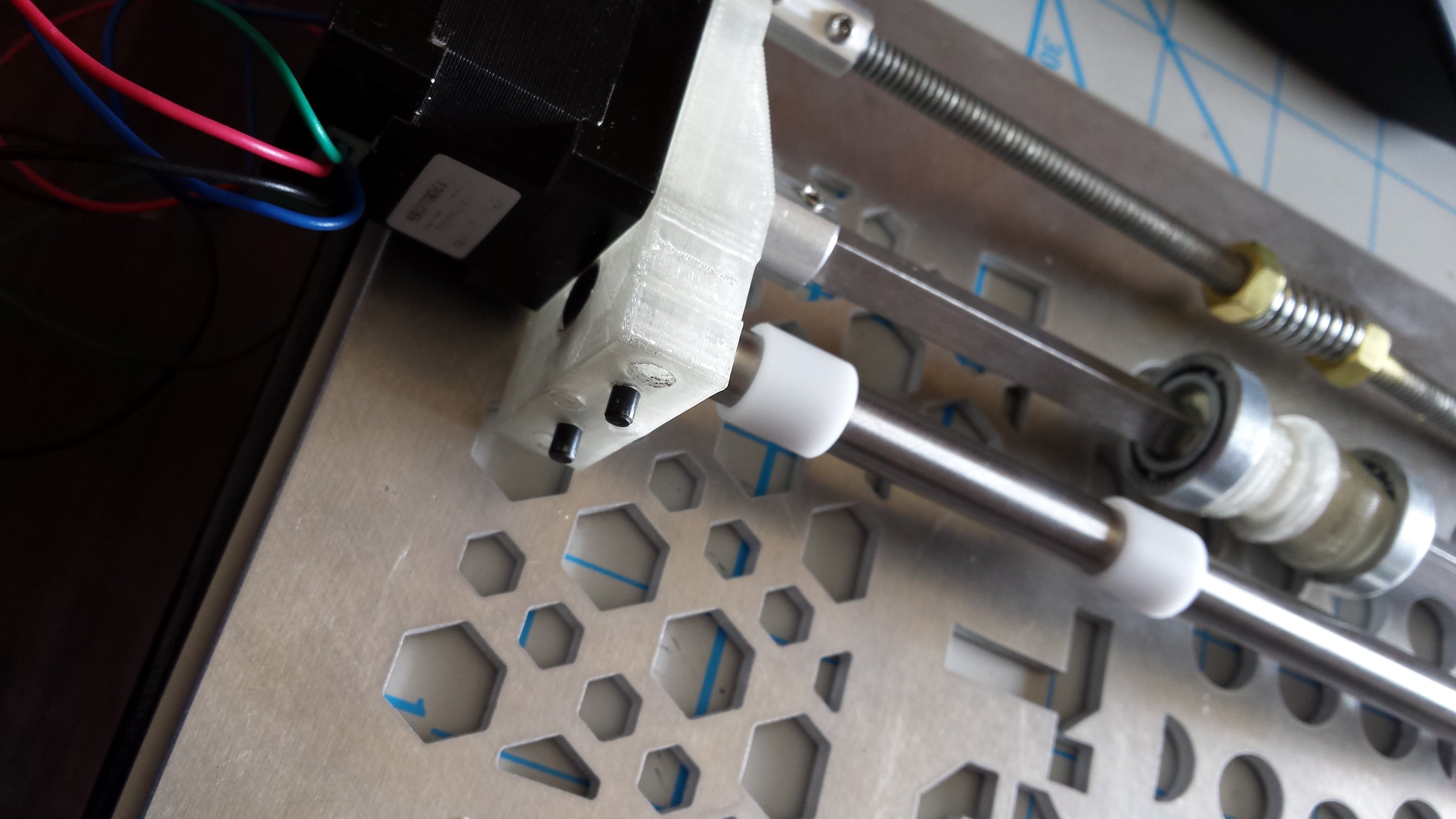
And here you can see the dowel pins inserted. This backplate is the original one I cut which is why it does not have holes to provide access to the guide rod clamping set screws from the back. I hate wasting material so I'll be adding these tomorrow on the drill press, the model has already been adjusted.
![]()
I plan on uploading the following parts to GrabCAD this week since they have been prototyped and are unlikely to change:
1. Z-Axis Guide rods
2. Lower Motor Mount
3. Upper Bearing Mount
4. NEMA 14 Coupler
5. NEMA 8 Coupler
6. Spectraline PullyThe Z-axis clamshell still needs to be modified and prototyped before it will be ready for release.
-
Z-axis Parts Finished
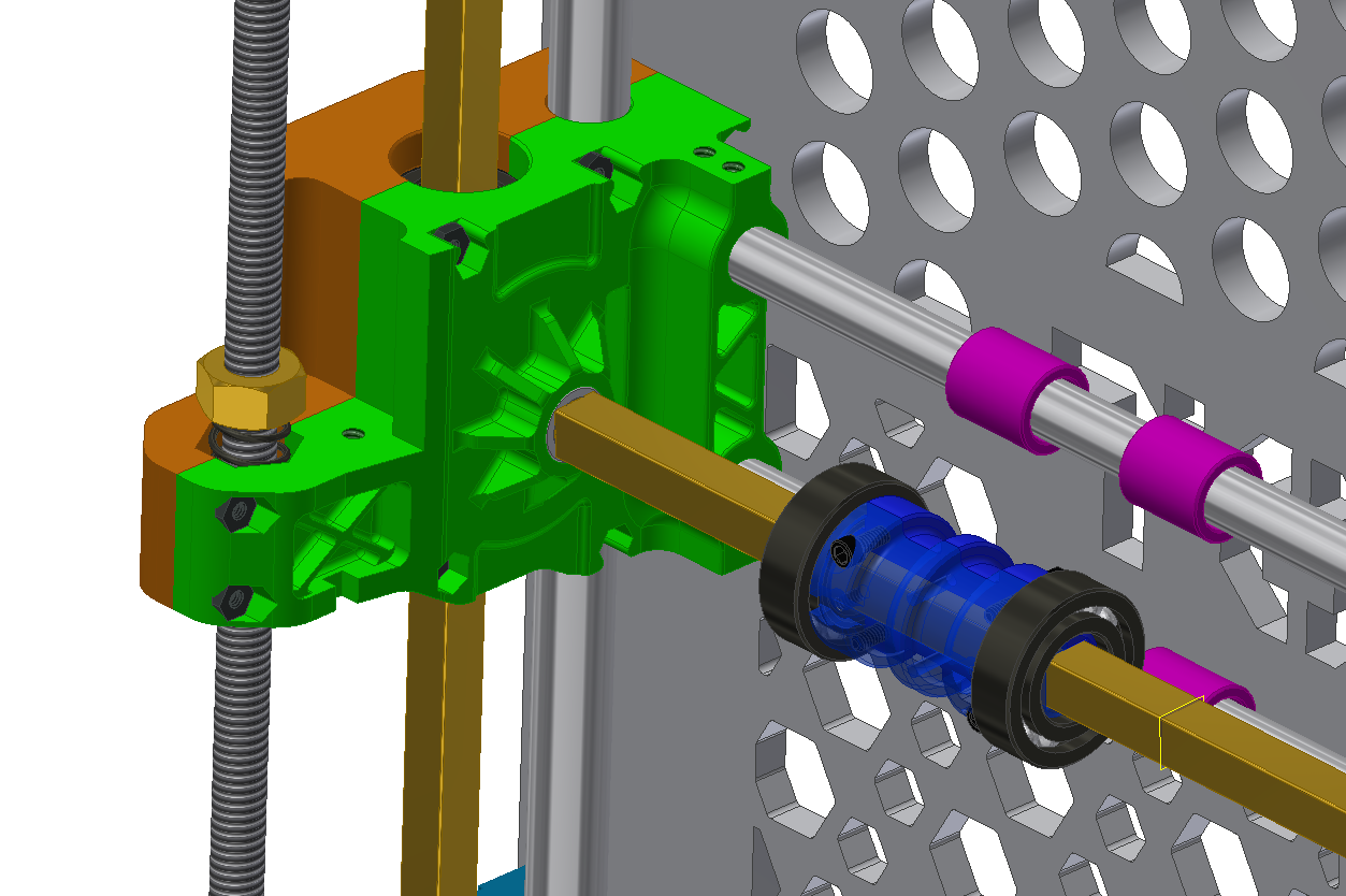
07/12/2014 at 06:09 • 0 commentsPreliminary prototype parts for the Z-axis (X-axis drive side) were completed today. I need to swap out the upper bearing mount and lower motor mounts as they were modified since the initial print. The goal for tomorrow is to have this side of the Z-axis running back and forth, with the ability to also run the X-axis spectra line pulley.
![]()
Progress has been slower the past few days than I was hoping, family and work tends to get in the way of projects. I'm hoping to have the opposing side of the Z-axis finished this weekend so that I can focus on the Y-axis truss that is causing so much controversy.
This weekend I will also be cleaning up this project, I think we have been doing a decent job of posting build/design updates. However I think the overall project description needs to be dramatically expanded, the BOM needs updating with all of the new parts.
Please post any comments and let us know what we can do to make this project better!
TOME - Portable 3D Printer
Portable and self contained FDM 3D printer designed to be the ideal tool for field hospitals short on supplies and nomadic engineers alike.