Philip Ian Haasnoot
-
Mockup stage 1
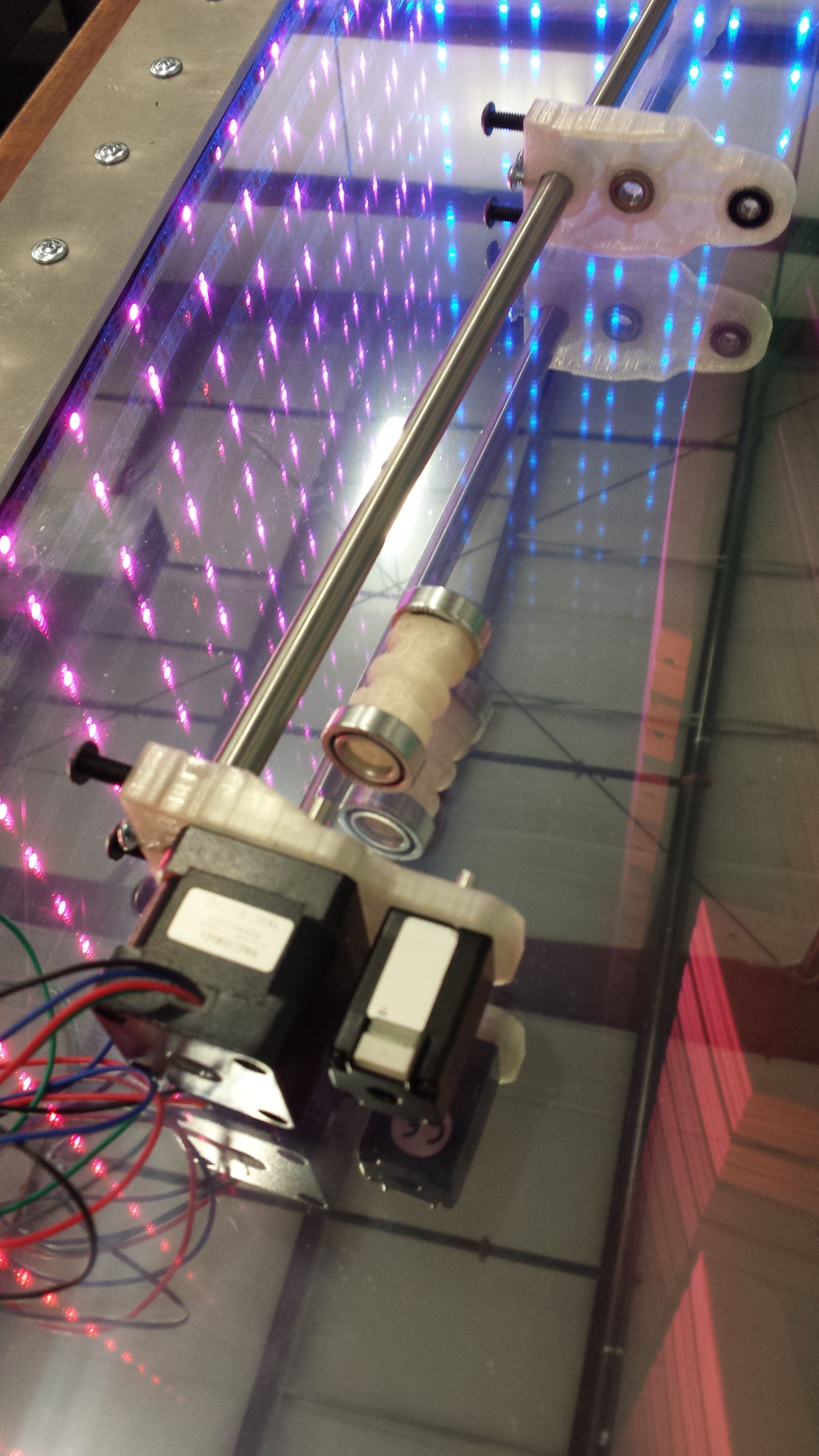
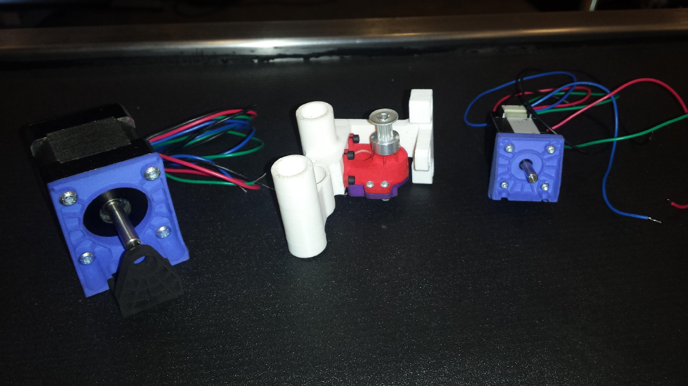
06/20/2014 at 03:20 • 0 commentsToday we received the first prototype part order, which contained enough of the components to start assembling the prototype to check for errors in the design. As stated before the clear PLA parts shown in the images will be replaced with 3D printed parts from Shapeways for the prototype. The spool in the center will need new bearings as the ones purchased from McMaster were of terrible quality, and the linear bushings were not the size we had ordered. Once we have the correct bushings and better bearings we will machine the first spindle.
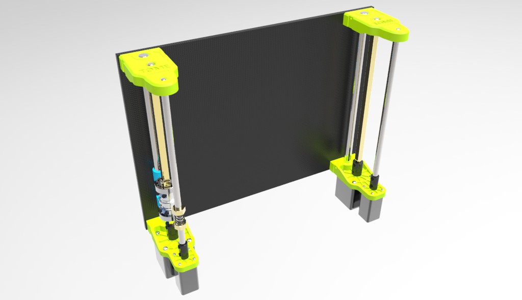
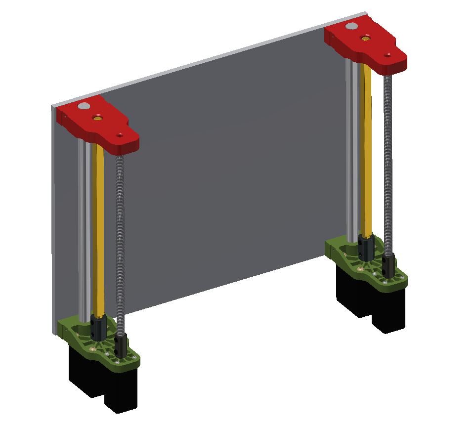
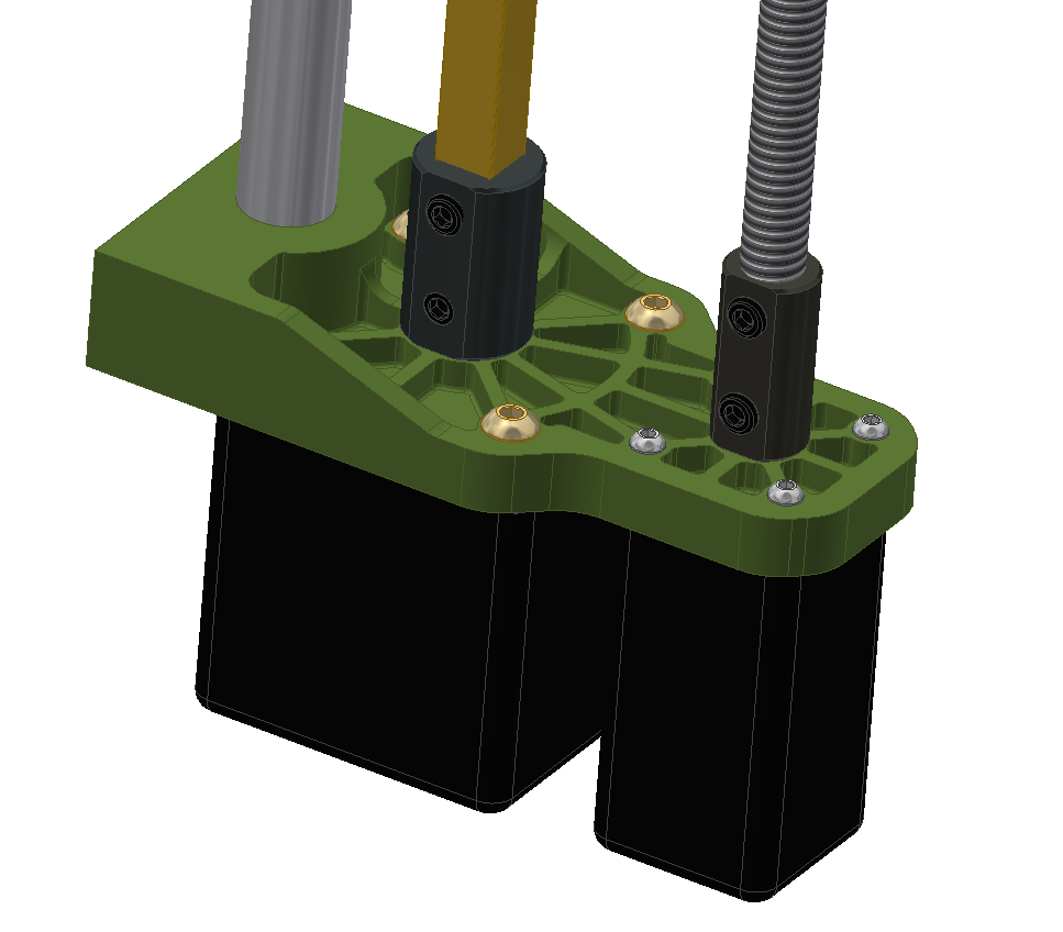
I plan to waterjet a prototype aluminum backplate tomorrow to mount this to, as well as cut the drill rod to the correct length. Here you can see the overall assembly clamped to the drill rod.
![]()
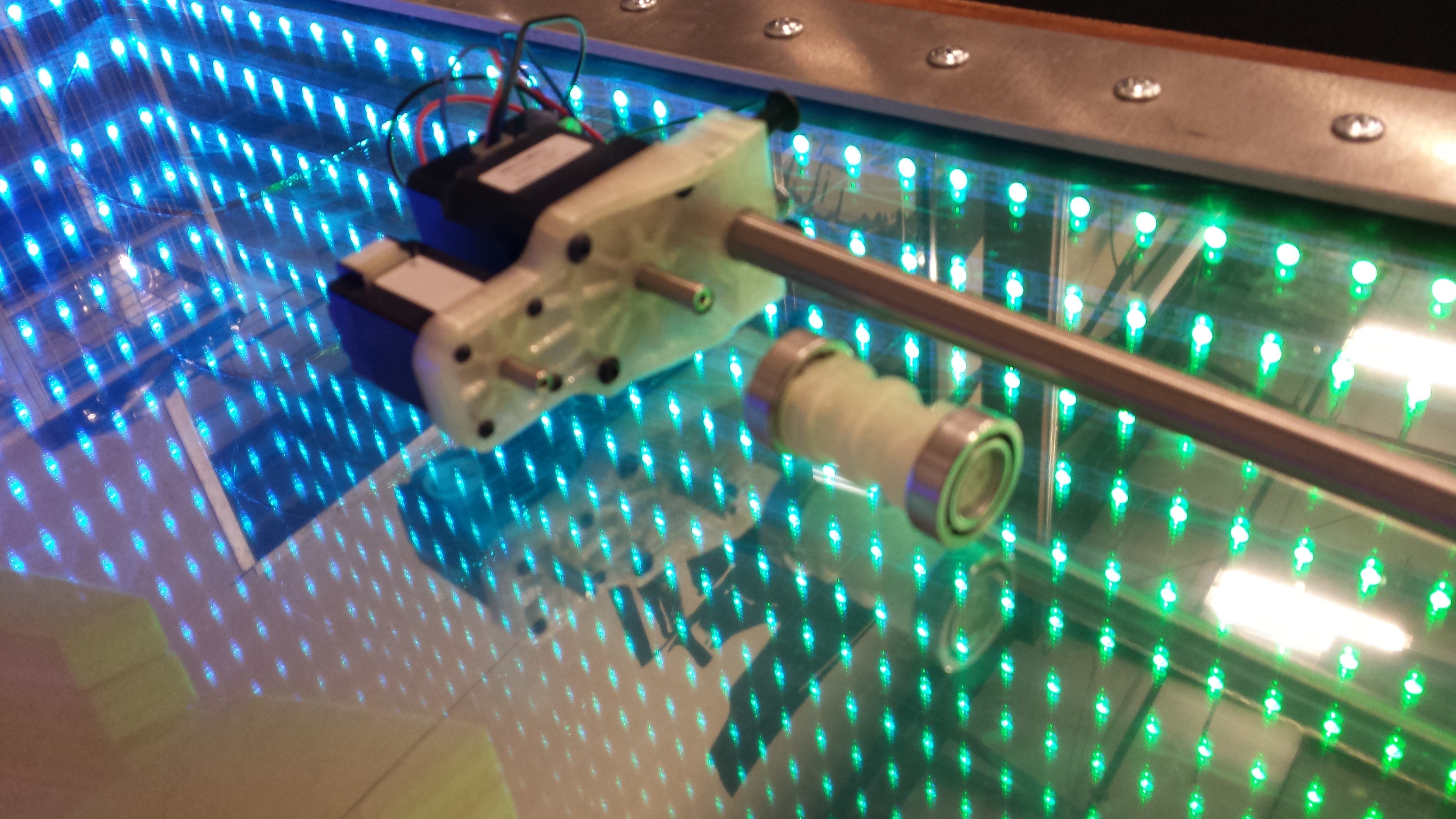
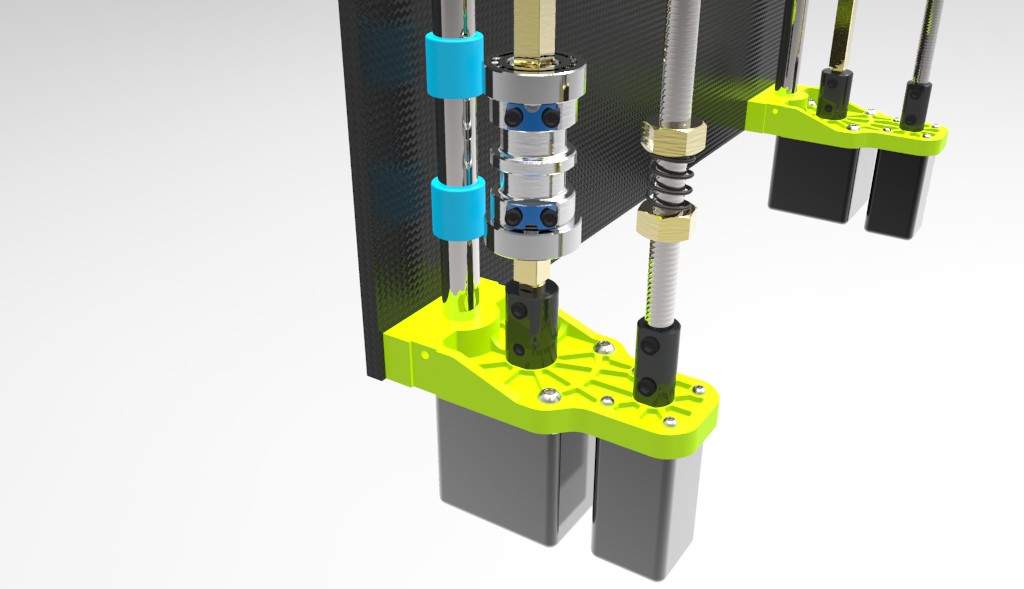
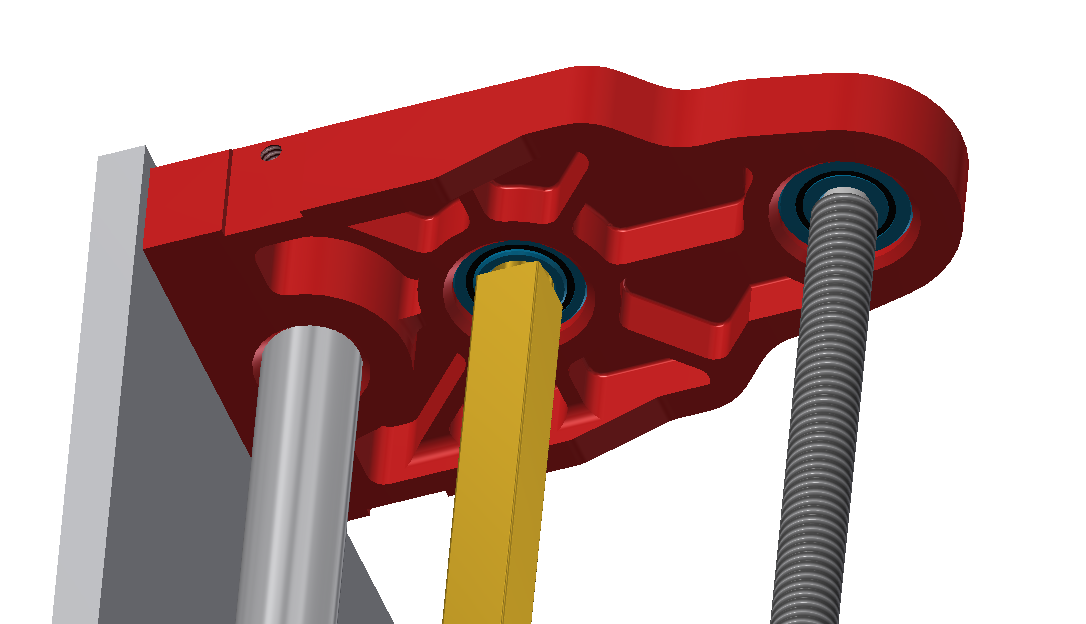
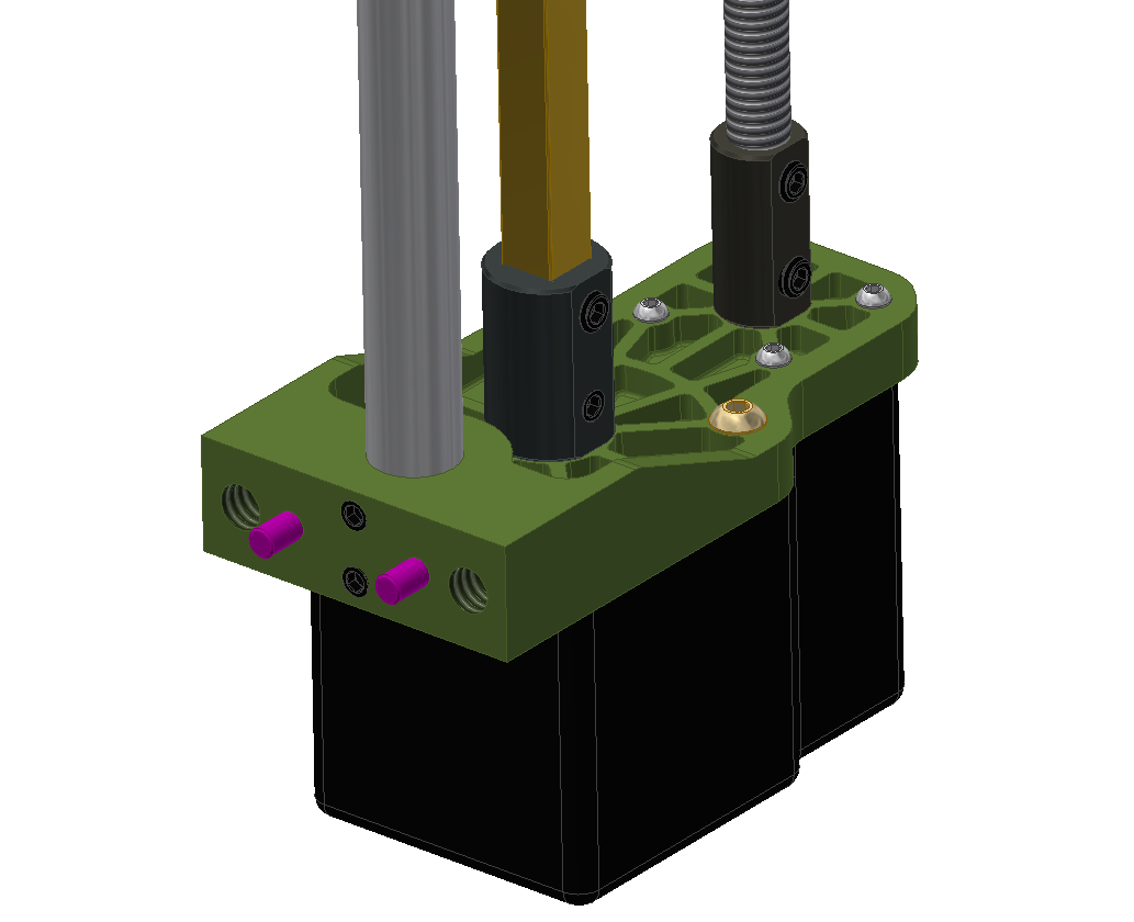
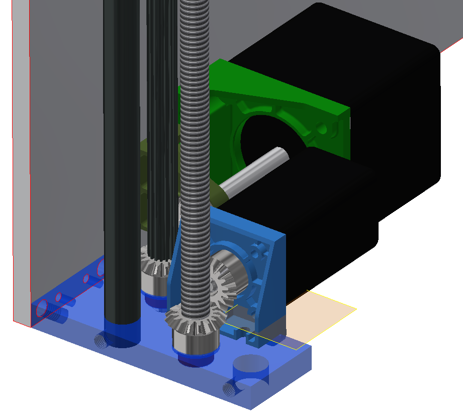
Here is a close up of the bottom motor mount and X axis spindle. As with most FDM prints there was some finishing required to get everything to fit due to excessive support material adhesion in the stepper motor counterbores. However this will not be an issue with the SLS parts from Shapeways. The spindle was printed to mock up the Z-axis which I plan on printing early next week.
![]()
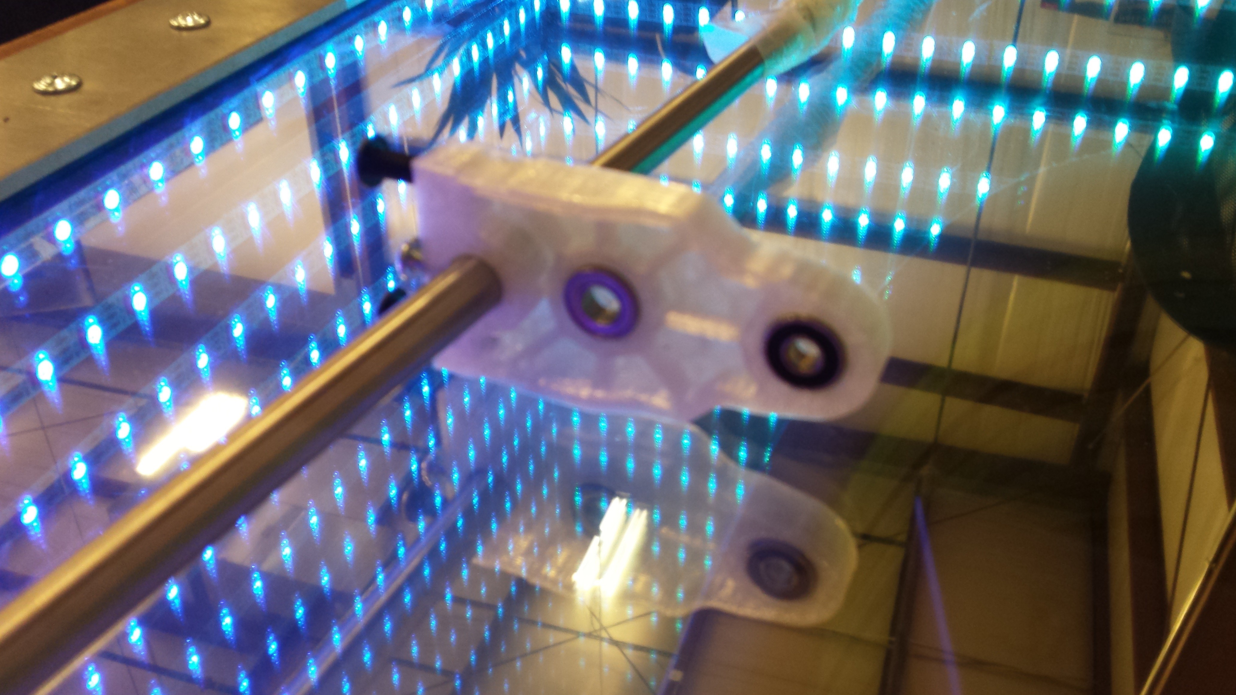
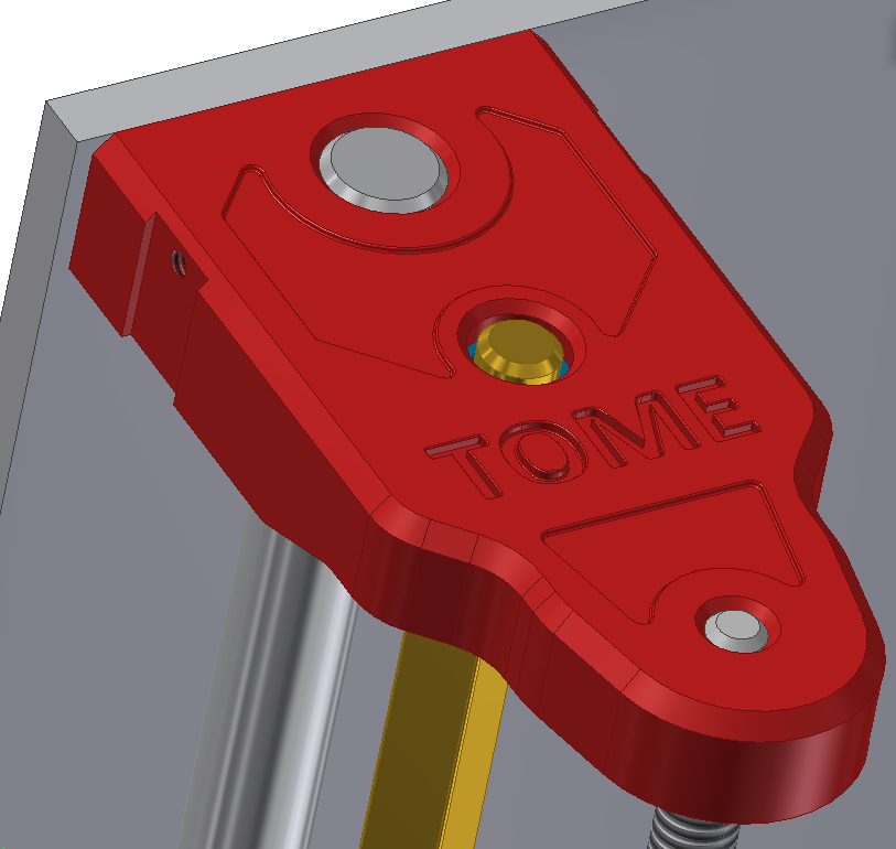
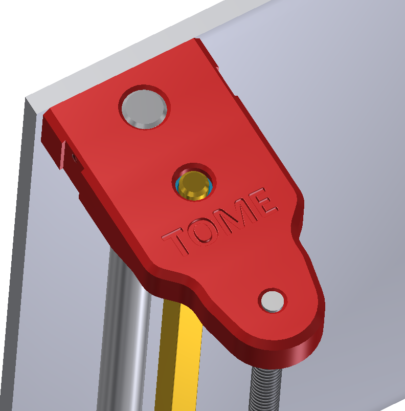
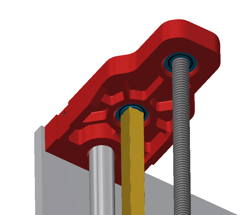
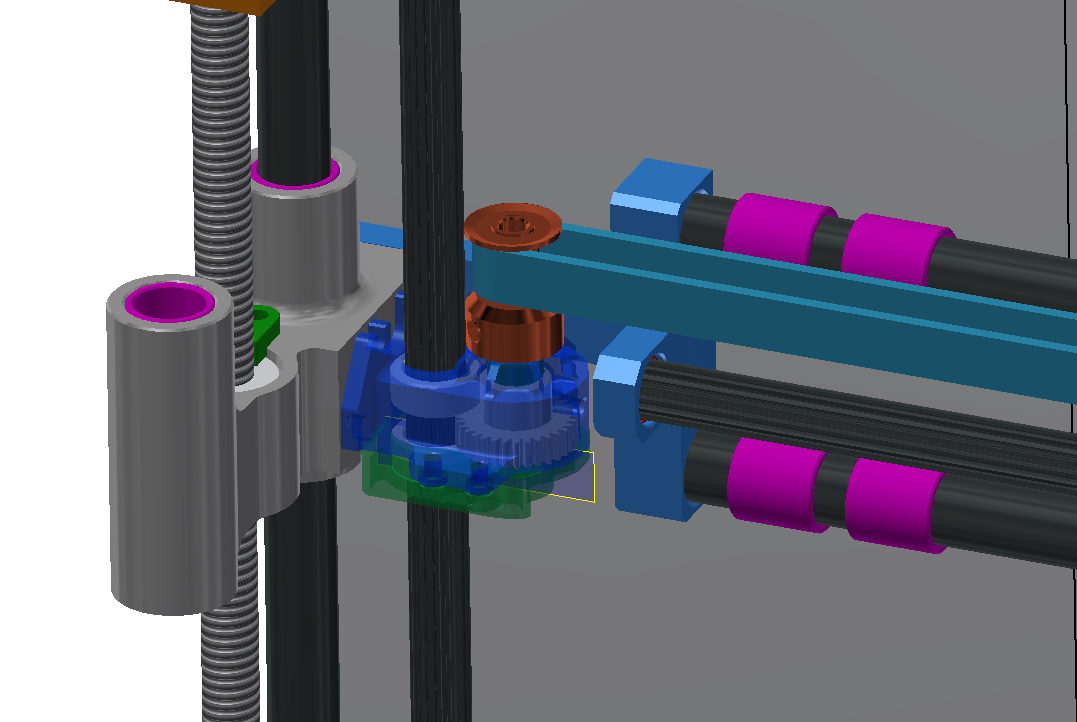
The top bearing mount did not require any additional finishing, both bearing pressed in without hassle. The threaded rod will be arriving tomorrow, and will be machined this weekend along with the z axis coupler to get that component installed.
![]()
The plan is to having a functional printing prototype by July 12th, with most of the work after that going to building the battery pack, filiment cartridge, and overall aesthetics.
-
First prototype Prints and component purchase
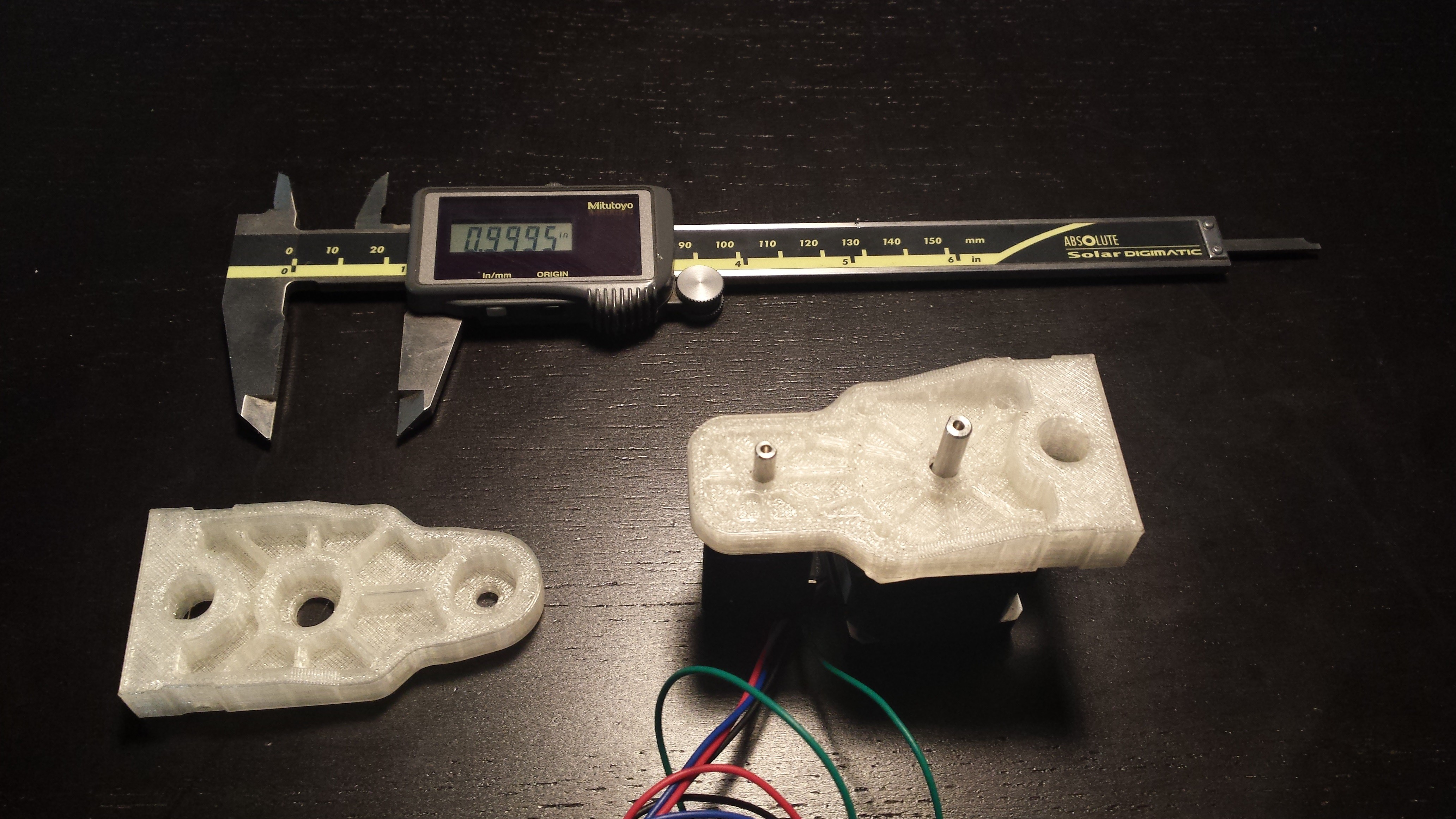
06/18/2014 at 02:42 • 0 commentsToday was a large step forward in getting the first prototype operational. The top bearing mount and lower motor mount were both 3D printed to check for errors and test fit the stepper motors. Corey and I agreed that we are confident enough in the design to start ordering components. If you scroll over to the BOM you will notice it has been expanded, the part order should arrive within the next few days and we plan to begin purchasing Shapeways prints to build the Full Z and X axis by the end of this week.
![]()
-
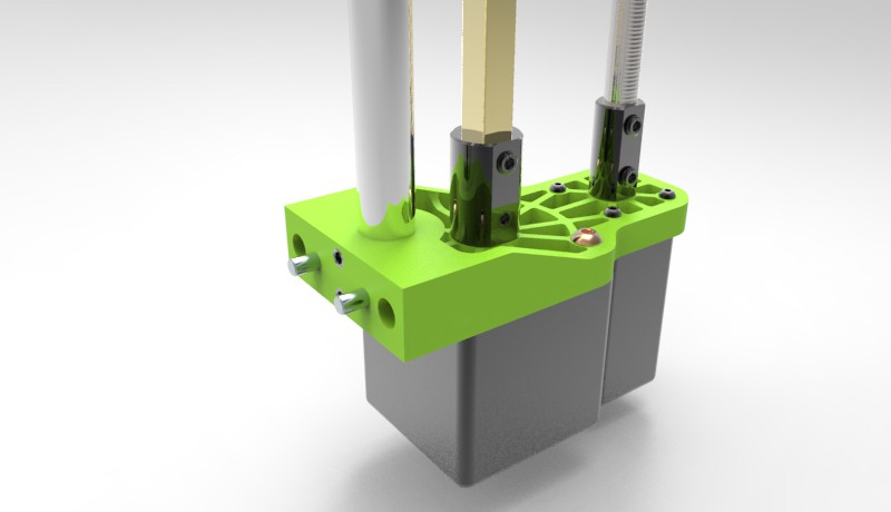
Photo-realism makes the world go round
06/17/2014 at 08:05 • 0 commentsI couldn't resist doing a few renders to better show off the progress that has been made so far. I really can't wait to get the full TOME prototype together and start printing. Stay tuned!
![]()
![]()
-
Z-axis and Mono-filament Drive
06/17/2014 at 07:48 • 0 commentsTonight I was able to take a break from unpacking to start designing the Z-axis carriages and Mono-Filament drive. Corey and I decided to go with this style drive as belts/pulleys would have been too bulky to fit effectively, neither of us are impressed with any of the belt driven 3D printers anyway.
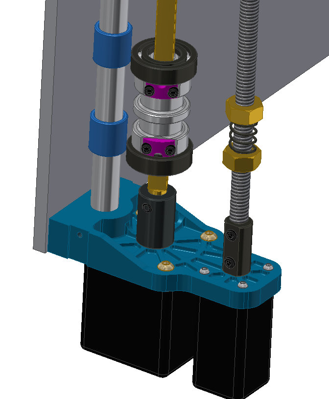
Here you can see the mockup for the Z-axis carriage internal components. Two PTFE or Acetal linear bushings (.375 in ID), Double brass 1/4-20 nuts with anti-backlash spring, the main spindle support bearings, and the main drive spindle (This spindle is for the X-axis drive).
![]()
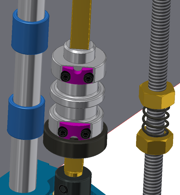
Here is a screen shot without the upper bearing, the spindle is a very simple design and will be machined out of 6061-T6 aluminum, the purple clamps will be 3D printed for the time being.
![]()
The next stage is to design the carriage to support all of the components, the Y-axis drive will be slightly different and I'll be working to mock that up tomorrow to start designing both Z-axis carriages.
The top bearing mount was also bothering me, and will need some artistic work to make it more visually appealing. I added two shallow reliefs in an attempt to make it look better.
![]()
Tomorrow morning I will also be 3D printing the lower motor mount to check the fitment with the stepper motors and the upper motor mount to show a sense of scale for the TOME.
-
BOM expansion
06/16/2014 at 08:24 • 0 commentsThe motor mount and bearing mount were uploaded to the TOME Shapeways shop to get an estimated cost for the BOM.
Parts that are 3D printed for this project can be found at this Shapeways store (https://www.shapeways.com/shops/RTH-Robotics?s=0)
The top bearing mount was finalized tonight and the X axis drive mechanism design will begin tomorrow. The current plan is to kick off the first round of prototype 3D printed parts next weekend (need to wait to my next pay check!).
![]()
![]()
-
Bearing Block Design
06/15/2014 at 08:56 • 0 commentsTonight I was able to get some design work done for the top bearing block. This component houses two bearings, one for the square drive and the other for the lead screw. This block also constrains the top of the Z axis guide rod, and has a slot on each side to accommodate an IR proximity sensor for end stops.
![]()
In the close up you can see the slot and mounting hole designed to accommodate the Sparkfun QRE1113 breakout board. I choose to go with an off-the-shelf breakout to make this easier to manufacture for those who cannot spin their own PCB's.
![]()
Slots for the sensors have also been added to the lower motor mounts. Both the motor mounts and the upper bearing blocks are symmetrical to bring the overall cost down if this ends up going to a larger scale production (Twice the parts, lower price per part).
I am planning to get the Z-axis carriages designed tomorrow.
-
XZ / YZ Motor Mount Redesign
06/14/2014 at 08:41 • 0 commentsFinally had time to sit down and redesign the motor mounts, as stated earlier they will be a single piece design to minimize parts count. We are planning to 3D print the prototype through Shapeways, but eventually these brackets will be CNC machined out of 6061 T-6 Aluminum.
In this render you can see the square drive for the X axis, guide rod for the Z carriage, and the lead screw to drive the Z axis. There are 2 NEMA 8 stepper motors (one per side) that work in tandem to drive the Z-axis stage. The square drive will be much easier to understand once more of the drive mechanism has been modeled.![]()
Here on the back end you can see how this carriage attaches to the main back plate. The back plate will be machined out of 6061-T6 aluminum, the TOME derives most of the rigidity from this plate. Both couplers will change slightly in order to 3D print them with sufficient strength to run the prototype.
![]()
And because I know everyone love shiny things, here is a photo-realistic render....
![]()
I have to attend an open house at work tomorrow, for anyone in the PHX area come stop by Local Motors for some fun! (6/15/14 Starting at 10:00Am). I plan to have the preliminary Z and X Axis stages finished by this weekend. Stay tuned!
-
First Progress
06/12/2014 at 06:53 • 0 commentsA brainstorming meeting was held today to nail down our goals, and verify that they are achievable within the timeline for the competition. Below is the summary for this meeting:
1. The stepper motors will be relocated to align them with their respective rotating shafts/lead screws to remove the bevel gears to increase print quality and overall ease of manufacturing. We are planning to machine the drive mounting components for our prototype, however stl files will be available so that they can be printed from shapeways (strong and light material) in order to manufacture the TOME from home.
![]()
2. We will be switching from a pinion wire drive to a square shaft drive. This is a dramatically cheaper option and simplifies the drive design significantly.
![]()
This week has been quite hectic for both Corey and I, this weekend we will be doing a large portion of the CAD work for this project. I will be focused on the overall XYZ motion system re-design, and Corey will be focused on the extruder and hot end design.
-
Dusting off the Cobwebs
06/10/2014 at 15:05 • 0 commentsThis project was first imagined in late 2012 and was briefly worked on as a personal project with the hopes of turning it eventually into a kickstarter. Working several jobs in preparation for a cross country move put this on hold. With a new teammate (Corey Renner) and a new venue for sharing this project (Hackaday.io) it is finally time to bring the TOME to life!
I've pulled all of the sourced components out of storage, over the next few days I will be getting back to work on the design once Corey and I have a moment to sit down and hash out final specifications for things like filament cartridge capacity, battery chemistry, and extruder design.
More to come very soon!
![]()
TOME - Portable 3D Printer
Portable and self contained FDM 3D printer designed to be the ideal tool for field hospitals short on supplies and nomadic engineers alike.