-
IGBT Purchasing Fail
11/06/2014 at 13:05 • 0 commentsSo I found a load of IGBTs going cheap on ebay (fairchild FGPF4633)
And then it turned out that I didn't really look at the data sheet properly.
I bought 40 of these, (to put ten in parallel per leg of the H-bridge)
However I really only looked at the maximum pulse current handling which is 300A of 0.01Seconds, and the low saturation voltage (VceSat is 1.55V @ Ic = 70A)
Which is good - running the transistors in linear modes of operation would have meant running them really hot!
The welding transformer draws 240V and runs from a 16 Amp supply.
The open circuit voltage is 48, (so the 330V max Vce voltage was well selected).
There is no specific current handling listed in the data sheet but there is a maximum power listed.
The welding transformer draws 240V and runs from a 16A supply.
That's a draw of around 4800 Watts.
I've decided to de-rate everything by a lot, but even so, that's still expecting that (if the transformer were perfect) that each IGBT should handle at least 480W of power.
Power handling is listed for the transistor as 30w @ 25 degrees
Temperature parameters are listed as:
4.1 c/w junction case resistance (Rjc)
and 62.5 c/w dissipation into air. (Rca)
Maximum operating temperature of 150degrees (Tm)
I'll assume ambient temperature is 25Degrees (Ta)
This gives me (working without a heat sink)
Pmax = (Tm - Ta) / (Rjc + Rca)
125 / 66.6 = 1.8W
Sadly much much less than the 480W I require!
If I add a heat sink (and insulator)
Rinsulation = 1 (Ri)
RHeatsink-Air = 4 (Rha) - what Wikipedia lists as a "standard" T0-220 heat sink
Then I get
Pmax = (Tm - Ta / (Rjc + Ri + Rha)
Pmax = 125 / 4.1 + 1 + 4 = 13.7 W (still a lot less than the 480 I need!)
in fact.
even if I said that ambient temperature was -55 Degrees Centigrade.
150 - -55 = 255 and that I had an ideal conductor of heat with a resistance of 0, case to heat sink, and a resistance of 0 heat sink to air.
255/ 4.1 (junction to case) = ~62W and is still less than the 480W I'd need to only use ten of these.
It doesn't really matter how bigger heat sink I use, these transistors will cook if I try to switch anything more than a few milli amps in a standard room temperature with a open circuit welder voltage of 48V (~ 24v actual welding droop voltage)
These were at least cheap - and I'm sure I'll find a use for them! -just not in this project.
If anyone can see anything wrong with my working above then let me know before I consign these to a parts draw! -
Open Source Licenses?
08/26/2014 at 12:17 • 0 commentsIt might seem a bit funny to say, especially since I'm still only about a tenth of the way towards the barely started point in both the projects that I have going on. but I'm uncertain of what open source license to use.
I've been a bit unsure for a while -at least since the mooltipass project changed it's license, I'm pretty sure that there is no sense in re-inventing the wheel so whatever license I use will have to be compatible with that particular license.
Originally I'd planned to invent my own licenses that simply would say, completely un-restricted and open -do what you like with it. but that would never be compatible with any existing license.
And since I've essentially "called out" commercial failings, in both of the projects that I'm doing, at either an expense and complexity, or saying that nothing commercial exists that does this at this level, it would seem like a crazy idea to effectively say to those businesses, I see a gap in the market, and here's a product you can use to fill it, and I want nothing for the work that I've put into it. -and yet at the same time a licenses that is too restrictive would kill any interest in a project that is supposed to be open source. And compared to large manufacturing corporations in foreign countries that have no care for intellectual property laws, one guy trying to apply a license might be like Canute trying to stop the incoming tide.
I'm also aware that copyright can be asserted to words, and not designs, essentially you can't really copyright or license hardware without staking your legal claim via an expensive patent route. I guess one blessing in all of this is that the hardware designs of what I'm doing are fairly well understood by most, use commodity components, and it's the software that supplies the special sauce... -and software is a copyrightable "entity".
So, suggestions on a postcard please (or at least in a comments.)
I'm looking for a license scheme that would enable any "user" of the hardware/software to freely obtain make and use the hardware and software. but at the same time would compel a "business" to need to seek permission for manufacture and distribution.
Basically, if you want to "use" or make the thing yourself, then I'd assert no restrictions what-so-ever, non-commercial people should be free, free as in without cost and without restriction.
But, if a business wants to manufacture and sell in bulk, and make money from my work. Then I'd like a tiny slice of that pie. -
Starting to build, testing the theory
08/20/2014 at 21:16 • 0 commentsI've got a couple of projects on here, this TIG (very hardware based) project and a project called home cloud which is very software based.
Whilst I have actually worked on these projects it's been fair to say that I've probably spent more time at beer festivals, cider festivals, motorbike festivals, on stag do's getting drunk, getting married, watching friends get married, visiting Amsterdam and doing a whole heap of work to actually pay for the bits to get two projects up and going...
So these entry videos were a pretty rushed job, however they did force me to layout the projects in an easy to view way.
Eagled eyes people will realise that the transistors laid out during my testing are actually power MOSFET, and not IGBTs. not to worry the final solution will be using IGBTs as it's the welding current that's important, not the voltage (FETS are voltage controlled voltage devices - so good for constant voltage devices (like a MIG welder) or good for amplifiers. whilst TIG welders require a constant current, -though it'd be feasible to use either with some feedback to measure voltage and current!
I'm in the stage of really seeing if this is feasible, the rectifier will handle about 60Amps, (30 each) and the FETS will handle around 20 amps, with 8 I have enough to position 2 either side of an H bridge. with an old low power welding transformer it would be possible to do some very limited welding. -though at this time I'm just dumping the output load into a light bulb.
in the video I've said that I've developing code for both PIC and AVR (where the AVR is an Arduino - essentially the main code base is written in C)
The program simple reads a table of lookup values used to set current over time. (imagine a table with values 20, 40, 60, 80, 100, that repeat, this would create a saw tooth wave.
this table is created by the operator and represents the current that they wish to see. (where current levels would be dictated by material type and thickness desired weld penetration etc.
a further table would be generated that would turn that current desire to voltage to be applied to the IGBT base to allow the current flow.
this simple maps the current to the output -
e.g
3Amps - 1
4amps - 8
5amps - 10
This table will relate directly to the linearity of the devices used in the output stage.
This table is used essentially as a starting point, and each output measurement is based on this. (this will stop surges at power on).
Once the output has been set it is measured and the output voltage adjusted from the signal generating controller, which will set the output of the IGBT devices, (providing feedback to adjust the signal if it falls outside of parameters.)Essentially using this system allows me to take a load (in this case a light bulb) where the resistance starts low and increases as the filament heats up allows a specific voltage to be set, and then feed back tested against the "map" - e.g. if the map of what to apply to the IGBTs is set too low for the components then this is compensated.
the video showing the components is here:
-
Costing transistors
07/09/2014 at 16:50 • 0 commentsthis will be the third time I've started this project update.
stopping due to it getting far too late in the night, needing to go to the work or wanting to go to the pub.
the simple fact of this project is it can't be built with off the shelf parts at the target budget!
to get 300 amps of handling at 4 legs of an H bridge is no easy task, and buying new can cost well over the £100 I've projected for everything.
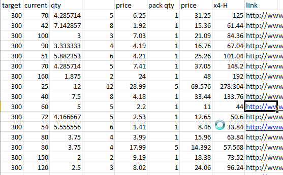
As it is I've got a simple cost analysis spreadsheet.![]()
the first coloumn is the target current handling capabilities.
in this case I've got a 250Amp max transformer.
but it won't be run from an industrial supply. running from a cooker socket will get about 180 amps at the torch, and from a domestic 240v 13 amp supply will give about 120 amps.
so why did I go for 300amps? well. I want the chance to use the box on an industrial supply, so if the opportunity ever comes to go to 415 volt, this box will handle it.
second, I want a comfortable margine of safety, 250amp max handling would leave me scared to use 250amp supply on full.
a 300amp max handling capability is a comfortabl 20% margin, it's almost double what I can use at the moment, and well over double 150% margin above what most people will have to work with.
The fact is that these things are expensive enough to buy the first time. I don't want to need to buy them again!
Though happily I'm getting my max current capabilities by running the devices in parallel, (e.g. 10 x 30Amp capacity IGBTs) to get to that 300Amp capability -you don't need to stack these if you don't want to!
the second column is the current handling capabilities of the transistor in question.
that's Maximim DC, (not AC where it gets a chance to cool!)
the third column says you'll need that many. (simple A/B)
the fourth column is that amount rounded up. (add more safety margin rather than take it away.
so what's the price, how many per pack, and so the total price.
that's either D * E / F to give me my total price.
then I have four pathways on the H bridge, so I need four times that amount. -lastly I've got a link to where I've seen the transistor. -mostly on ebay and other end of line surpluss type places.
This does mean that each design will be slightly different.
to compensate for this, I'll make the ADC/Amplifier stage that drives the H bridge adjustable, -that way, the Maps used in the uC can stay standardised, and the transistors can change.
At the moment costs are looking to break down like this.
Auto coil for driving HVHF - £5 - £10
uC £3 - £7
LCD screen £5 - £20 (depending on size)
small components (op amps, thermistors, resistors capacitors £5 - 10)
Rectification of welding transformer £10
IGBT for H Bridge £30 - £60
Wires (big big wires) £5 - 10
small wires (I'll allocate £5, but mostly re-use wires I have)
Gas Solenoid - £5 - £10
giving a total cost of £73 - £122
On top of this there will be costs of Case, connecttors, and heatsink.
I'm toying with the idea of adding optional water cooling, as it stands I can currently use currents approaching the need for a water cooled torch. and at the very leave water cooling the heat sink used on the rectifier and IGBT bridge would reduce the heat sink costs.
Above I said I'd allocate an amount but mostly use what I have, this will be broadly true for the whole project, I'll re-use parts, but produce a BOM "as if" I hadn't spent half my life collecting junk. -
Controller (and conectivity)
06/27/2014 at 15:47 • 0 commentsSo I've started evaluating microcontrollers for the "brain" of this system. I think I've said before that I'll be using a PIC chip.
The actual chip I'll use is still to be decided, but since I've got a few old chips laying about I'm going to start using these and plan to port code later.
The chip I'm going to start using it the PIC16F877.
Esentially it seems like a good starting point. the 40 pin chip that I have in my spares box has 8 Analog pins.
will be used for:
Current Sense
Voltage Sense
Temperature sense of the rectifier/H bridge heatsink
leaving 5 spare inputs for analog control of the settings.
(additionally leaving plenty of pins for driving an LCD, having display lights and acceptting inputs from button switches etc).
The settings the operator inputs to the machine won't be strictly analogue however. -more likely there will be step changes than true smooth analogue operation. for some settings I envisage up/down buttons would be a better.
I've spent some time trying to make sense of fuel maps for my car, (with the intent of tuning it), and I've more or less decided that's how I'd like this machine to work. -i.e sensors detect inputs, and given those inputs the machine is able to determine what fuel to put into the engine, how much boost pressure to apply with a variable turbo etc.
In this case however the machine will check the position of the switches, and detect the current flow at the output, continuously conparing what's happenning, and making adjustments to make the output make the operators wish.
I believe that it would be a neat idea to enable the use of maps to select waveforms etc on this machine, that would enable people to determin what the waveform should look like. (a basic map) and then an operator can "tweak" parameters with the machine settings. (amplitude/frequency)
Which leads me onto I guess the party piece of this machine.
There will be a few pins left for external communication. an RS232 (serial) port will allow for either new operation maps to be uploaded to the machine, or allow for the welder to be conputer controlled entierly.
Allowing this ability to upload new maps (or waveforms) to the device means that I'd expect that a person making this device was able to decide that they may like a specific waveformation and chose that.
Additionally the "maps" will be able to select a preference to ignore the pannel controls.
What this means is that if I'm performing a task that will be repetative rather than trying to remember where the dials are set or play around with them, I can create a map setting all parameters AND turn off the pannel controls within the maps.
Kind of how the "limp mode" map in a car is set such that no matter what you do it won't go over a given rev range. in this case, the welding current would be restricted,
The device will come with six essential maps,
Sine wave
Saw tooth wave
Modified sine
and square tooth
DC
DC pulsed
Most maps will essentially be 2 axis maps,
the current selected will form the Y axis of the map.
and time would form the X axis.
The actual current will be measured, and from this a delta value derived that would be used to adjust the output.
The output from the chip will be a simple number, then a DAC will convert this to an analog voltage, which will power the IGBT transistors (voltage controlled current device) which will operate within their linear region
The purpose of using maps will be to save processing time, for example, a sine calculation whilst not impossible on chip will take some time. Looking up a reference from a map/lookup table stored in memory will greatly improve the processing time, allowing more switching time. -
Connections to the welding transformer
06/25/2014 at 15:08 • 0 commentsSo the first thing to think about is exactly how will this welder converter connect to the existing welding transformer that I (and you if you're wanting to build this) have.
Somewhere near the top of the list of concerns when dealing with anything that plugs into the wall is (or should be) safety.
It is tempting to just have a couple of bolts sticking out the back pf the converter box to just attach the electrode holder to and the earth clamp to. (literally clip them on), but that's not fantastically safe, and likely to come off half way through doing something, more than likely at some sort of critical stage...
Something that I will say is, you can just attach a connector to this and bolt is directly to the back of the machine, or even take the existing electrode wire and earth clamp and cut them up and permanently install them into the converter box hard-wiring the cheap transformer to this box.
However I'm going to go a route that will "look" a bit nicer, but serve no other functional purpose.
The connectors used on the higher end welding machines are like bayonet connectors, and are made by a company called Dinse -therefore I'll refer to the connectors as "Dinse connectors".
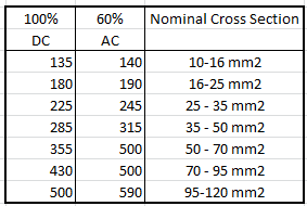
These come in various sizes, all in mm2 size ratings, - which will determine the current handling capability of the actual connector.![]()
to decide on the size of connector you need look at the maximum current rating of your machine, and pick the next biggest size.
For example: if your welder has a maximum welding current of 120Amps, then a 10- 16mm2 connector will be enough.
If you plan to put a 250Amp supply onto the converter box, then you'll want to go with the 285 connector 35 - 50mm2
For my welder, the cables are fixed to the transformer. -this will be true of most "cheaper" welders.
I'll need to cut the cables, drill the control panel and install Dinse type connectors on the main transformer, and attach connectors to the existing earth clamp and electrode holder.
(so after that I'll have the same capacity stick welder, but I can pack it away a bit neater!?)
In order to make it so it only works one way I'll install chassis plugs onto the tig converters back. which means that the connector attaching to the weld transformer needs a plug at one end, and a socket at the other. this means that you can't plug the transformer into the welder output.-so I essentially get a bit of an extension cable for my existing welder setup also.
I'm going with the Dinse type connectors, but will buy off brand copies in order to reduce costs for myself.
Welding Transformer
2x chassis Socket
Connecting lead
2x inline plug + 2x inline socket
Tig box input
2x Chassis plug
Tig box output
2x Chassis Socket
so, four chassis sockets, two chassis plugs, two inline sockets and two inline plugs.
Individually, (and in the size I want) these start at around £5 each on ebay.
but scroll down the listings and you'll find some people list sets. I've just seen set of 2x chassis sockets and 2x inline plugs for £13 (free P&P) this puts the cost down to £3.50 each.
it's also worth searching for CK size, in this case CK35-50
At this price that's £35 for the set up I want.
Next cables need to be looked at
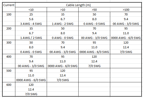
Again a simple table![]()
(weirdly the American wire Gauge doesn't go high enough to express the chunkiest cables required!)
the table shows the crs sectional area, under that the diameter of the cable in mm, and under that the American wire gauge and standard wire gauge (other wise known as imperial or British)
Again I'm looking for a max capacity of 250Amps, so will look at the 300amp row. I'll only need a few meters (less than 10!) so only need 50mm2 conductor cross section. (this is clearly the biggest cable I could use with the 35 - 50mm2 dinse connectors (if I wanted a longer weld cable then I could use a 70mm2 conductor, but would need bigger plugs.)A quick look around shows this wire to be seriously expensive when bought in rolls.
However, you only need a short length (to connect the welding transformer to the converter box), in order to find this wire in convenient sizes search for 300amp jump leads. Which I've seen for £5.
As for getting my budget of sub £100...
theses connectors are NOT included.
why?
well I could easily take the price to well over the target budget with non-essential fluff. Laser cut aluminium case? with logos, powder coated?
why not? and if I'm really happy with what I've done then I'd happily spend some time and money giving it a good case.
At the moment, the only thing "needed" will be 2x Dinse plugs for the output to mate the TIG converter to a torch.
and even they are non essential as you could cut off whatever plugs came with a torch and hard-wire it to the converter box. or use some bolts and some lugs and nuts...basically, there is a £40 spend I'm going to make now (plugs and wires) I expect that if you want to save money you'll just cut off the electrode holder and hard-wire the transformer to the box at zero cost for connections. -in the end it's your device and your choice.
It might be cheating, but the project goal here is to get a TIG converter for £100, not get a nice looking one.
(I'll keep track of both essential and non-essential budgets in a BOM round up.) -
Block Diagram Design
06/23/2014 at 11:48 • 0 comments![]()
(Image attribution: From the Wikipedia article on TIG welding. Author: JoJan)
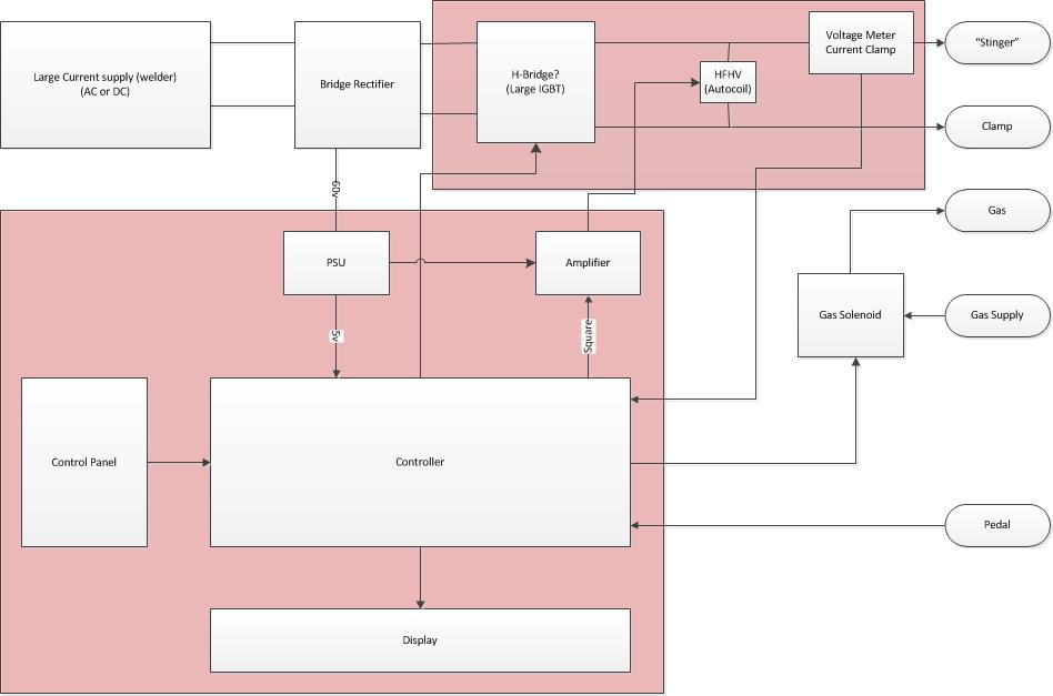
After a lot of thinking about this project I've finally settled on a "basic" hardware implementation.
Power Source:
Essentially the power source for the project will be a welding machine, either AC or DC can be used, regardless of the actual machine used the welder output will be fed through a full wave rectifier. meaning that DC will be used inside the box. - E.g DC stays DC and just passes through the diode, AC will become DC.
This DC should be around 60v at open circuit, although voltage will sag significantly whilst welding. The internal controller that generates the necessary waveforms will use a regulated 5v supply, the welding current should not sag to less than 5v. and so the welding machine should be reasonably safe from brownout conditions, However if it appears during testing that the voltage from the welding transformer (initial power supply) can sag so low during use the the micro controller used does brown out, then the solution will be to provide a backup battery, which will be charged during "non-weld" time. and provide power at all times.
(the welding transformer I intend to use provides very large current (250 Amps) with a 40% duty cycle. lower amperages increase the duty cycle, the machine is rated near 100% for 140Amps and lower, so capacitors, which cheap compared to batteries and may have large power storage capacity may not be useful for protection against brownouts at near 100% utilisation.)
The aforementioned controller will likely be a PIC 8bit micro, though I am yet to decide on the exact model. the choice of PIC micro is based on nothing more than I have experience using it, and have a PIC Kit II programmer. Code can be easily ported to Arduino if a person has a similar "I have this and don't want to change" mentality.
The controllers main job will be to read and store the operating parameters set by the operator. Generate the waveforms appropriate as dictated by the operator, and sense what is happening at the welding electrode output in order that the parameters can be controlled via a negative feedback system.
Welding Gas:
The gas Solenoid that controls whether gas flows, and when gas flows will be controlled by the micro controller, in this way a pilot arc (HV) may be sensed and pre-gas may be applied automatically before the main welding arc is struck.
Welding arc:
The welding arc will be controlled via IGBT transistors, these are chosen for their high voltage/High current handing capabilities.
HFHV / Arc Start circuitry:
The arc start circuitry will be provided by a high voltage high power source.
This will be based on a car coil.
The micro controller will generate a high frequency square wave (5v), This will be fed into an amplifier where the voltage will be increased to 15 volts. The square wave used by the micro controller causes the magnetic field in the coil to collapse instantly generating the high voltage spark, the high frequency used ensures that there are many sparks per second, appearing as a near constant stream of Electricity forming an ionised (lower resistance) path to the work piece ensuring that the welding arc can be struck, or stays struck when AC welding.
Feedback:
Near to the welding electrode output there will be some circuitry to sense the output voltage and current of the device.
Generally whilst welding the operator will specify a current setting, this is a current limit,
The amount of current in the welding circuit controls the temperature of the welding pool. -obviously on 1/4 inch steel a lot of heat is needed to ensure adequate penetration of the weld. but trying to weld very thin 16 gague steel with the same current settings will cause the work piece to simply melt.
A rough rule of thumb for mild steel is that 30A per mm is needed.
http://www.mig-welding.co.uk/tig-calculator.htm
So it is clear that it's no good simply switching the current on and letting the welder do it's own thing. some kind of current control must be implemented.
The method that I have decided to chose (for DC welding) will be to use pulse width modulation, that is turning the welding current off when it is too high in order to limit the current flow to the work piece.
It is not possible to measure the current via inductive coupling of the DC system, therefore the welding current setting at this operation will be a percentage of the input welding current. -as the welder power supply is a welding transformer, it means that the operator can select a desired current at the transformer (usually by dial indicator attached to the shunt) and then set this converter box to 100%. current may then be reduced mid weld via use of the foot pedal.
When using AC, the current will be measured via inductive coupling (much like a clamp current meter).
current will be limitted in this AC mode be operating the IGBT transistors within the linear region of operation, limiting the output voltage will limit the output current.
![]()
The diagram has two large red boxes. these denote where shielding should be applied.
The general world should be shielded from the HVHF arc start circuitry. and the control circuits should be shielded separately from both the HFHV and external interference.
The entire circuit should be provided in a plastic case for operator protection.
Large heat sinks will be required for both the diode bridge and the H-Bridge circuitry. Additionally fans may be used.
At the point I have an idea that active temperature monitoring may be beneficial for component protection (thermal cut out when the machine gets too hot. -but I have not fully thought this through hence it is ommitted from the diagram.)
Stick / TIG converter
An budget add-on box to convert a stick welder to a TIG welder. This project aims to produce a low current TIG welder for <£100
 Danny
Danny