Curt White
-
Tingle Research Paper Published
05/30/2019 at 20:22 • 1 commentThe Child Mind Institute Matter Lab has published a paper based on data gathered from the Tingle gesture recognition device (the primary prototype presented in this Hackaday project).
Check it out:
https://www.nature.com/articles/s41746-019-0092-2
Thermal sensors improve wrist-worn position tracking
Jake J. Son, Jon C. Clucas, Curt White, Anirudh Krishnakumar, Joshua T. Vogelstein, Michael P. Milham & Arno Klein
npj Digital Medicine 2, Article number: 15 (2019)
-
Building the Tingle
10/19/2018 at 19:27 • 0 comments1: Unboxing and Dissembling the N68 Fitness Tracker
![]()
This is the fitness tracker used as a foundation for current Tingle prototypes. It can be had for $30-40 from China ( Link1 , Link2 , Link3 , Link4 ) or $63 on Amazon Prime if you are in a hurry. The primary reason I chose the N68 it its cast metal enclosure and magnetic power adapter. The appearance of Tingle prototypes is extremely important. We will be asking parents of vulnerable children to put these devices on their child's wrist. A finished, off the shelf appearance is important to gaining their trust. In addition, these prototypes are handled by decision makers at CMI and potential funders, both of whom appreciate a polished product. The N68 as a color OLED screen, KX126 accelerometer, 8MB GigaDevice FLASH memory IC, vibration motor and simple LED/Photo-receptor heart rate sensor.
NOTE: As I'm documenting build steps I will be showing pictures of four devices being fabricated. Building these prototypes one at a time is very tedious. Also, multiple prototypes means you get to see multiple examples of each build step.
![]()
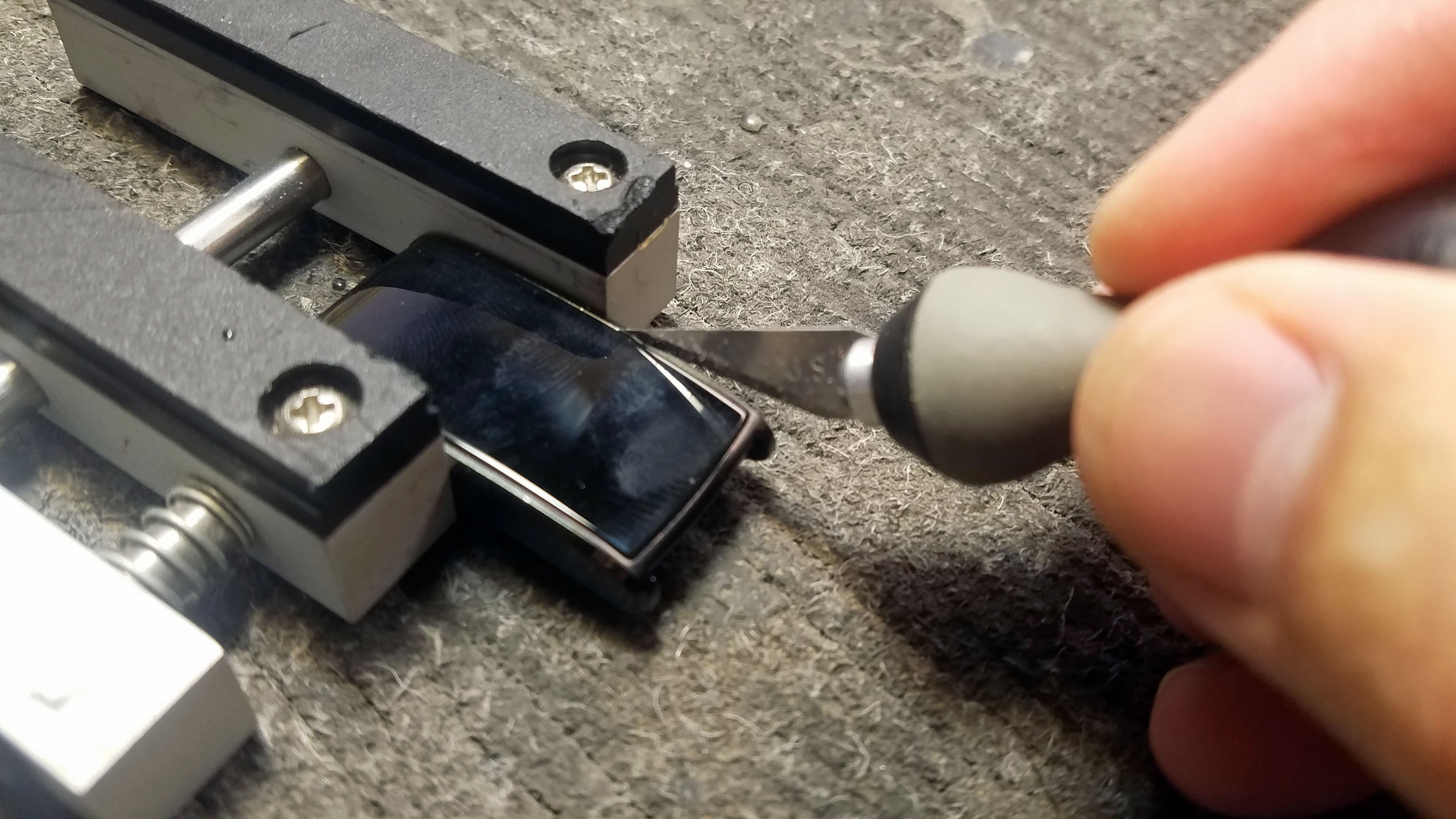
The strap and glass cover are both removed. The cover is attached with glue. I use a hobby knife to cut around the edges of the cover, thereby loosening in.
![]()
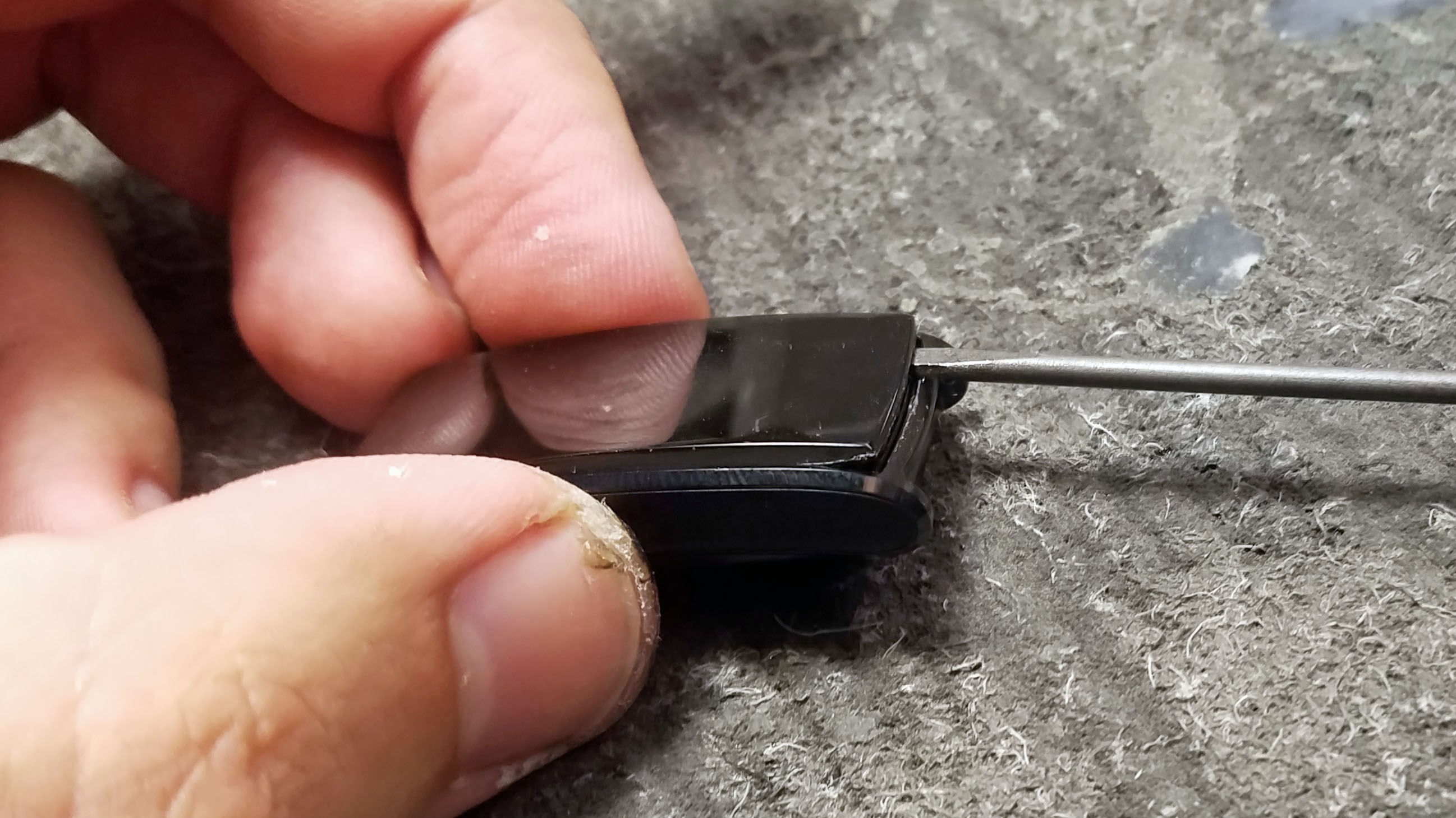
A small screw driver is used to pry up the cover.
![]()
Here you can see the cover removed and placed upside down. The bottom section of the cover has a contact for the touch sensor affixed, and the top has an extension of the Bluetooth antenna. There is also a PCB antenna embedded in the circuit board itself so this isn't strictly necessary.
![]()
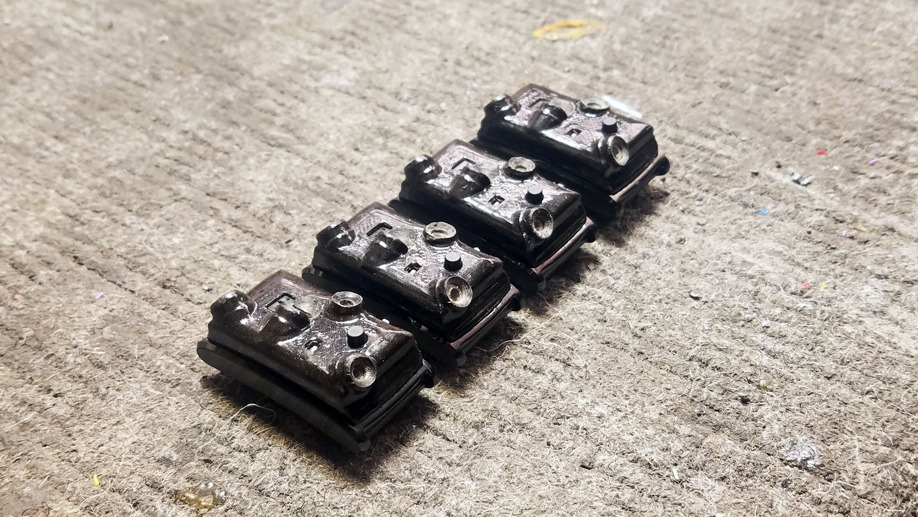
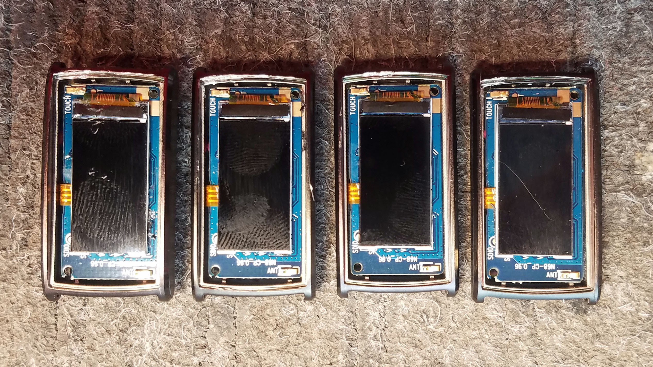
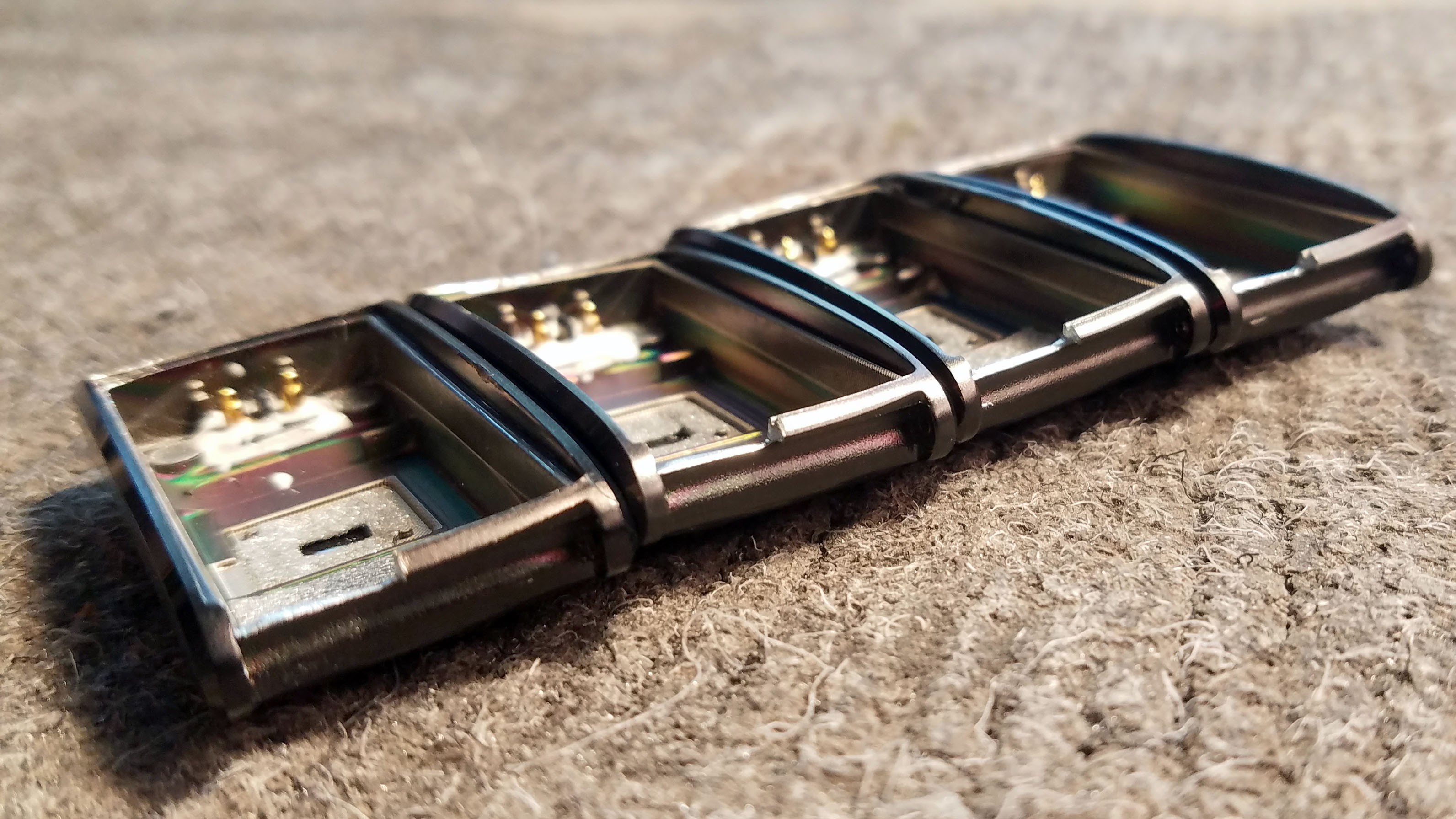
Here are all four N68s with covers removed.
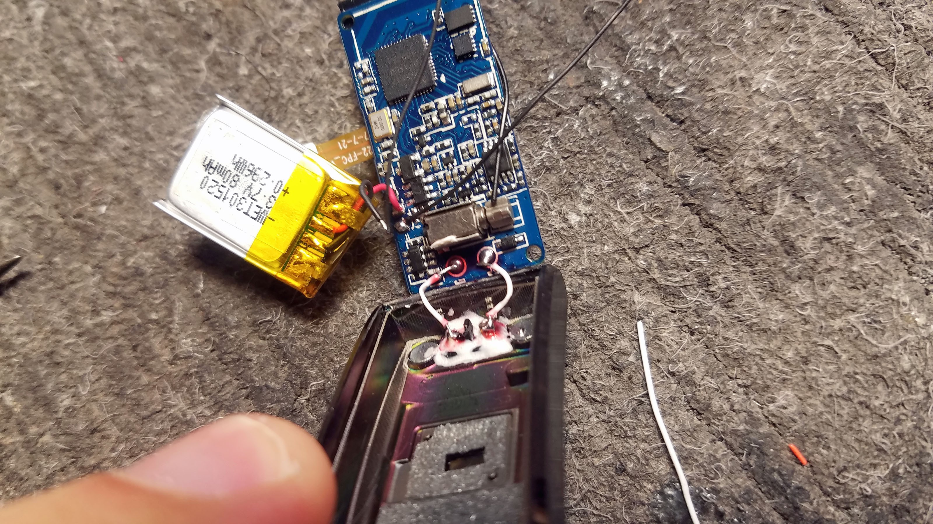
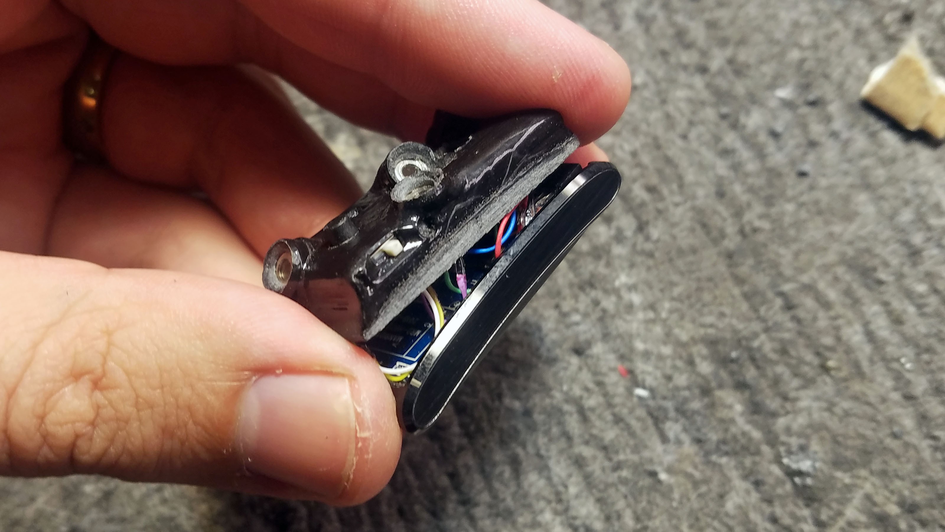
![]() The electronics have been removed from the enclosure. The battery and heart rate (HR) sensor are lightly glued to the bottom of the enclosure but can easily be lifted out with a small prying tool.
The electronics have been removed from the enclosure. The battery and heart rate (HR) sensor are lightly glued to the bottom of the enclosure but can easily be lifted out with a small prying tool.![]()
Here you can see the green LED for the HR sensor lit up. The HR sensor is not currently used in the Tingle prototype but this is just a matter of programming, these sensor is readily available for use. During a clinical study we hope to monitor HR during detected compulsive behavior events. The HR sensor might even offer additional filtering of false positive detections since elevated HR is correlated with the anxiety that underpins compulsive behaviors.
![]()
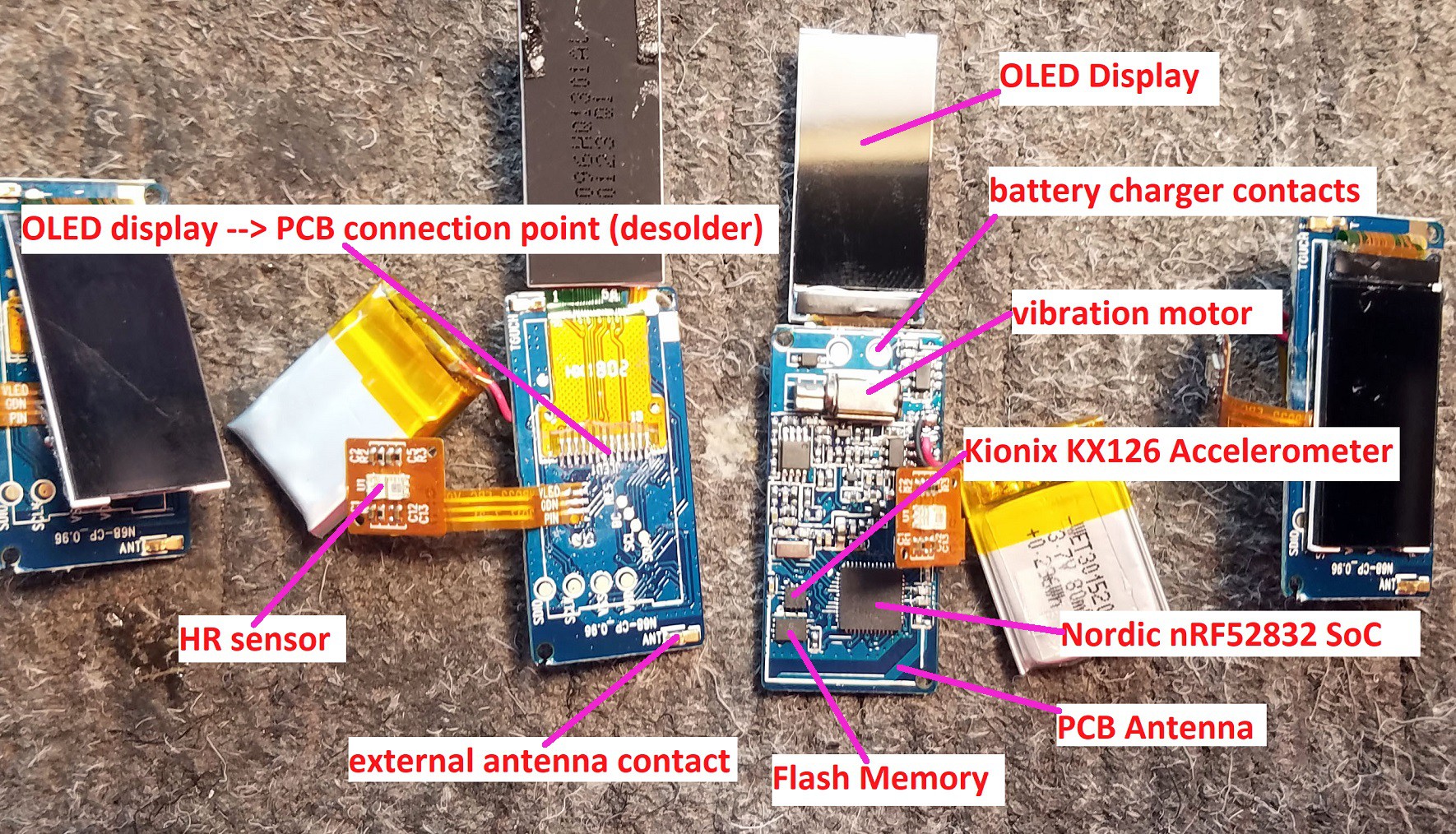
N68 Fitness Tracker Components
![]()
Closeup of N68 PCB ICs. External flash and HR sensor are not currently used in the Tingle but could be implements by simply writing additional code.
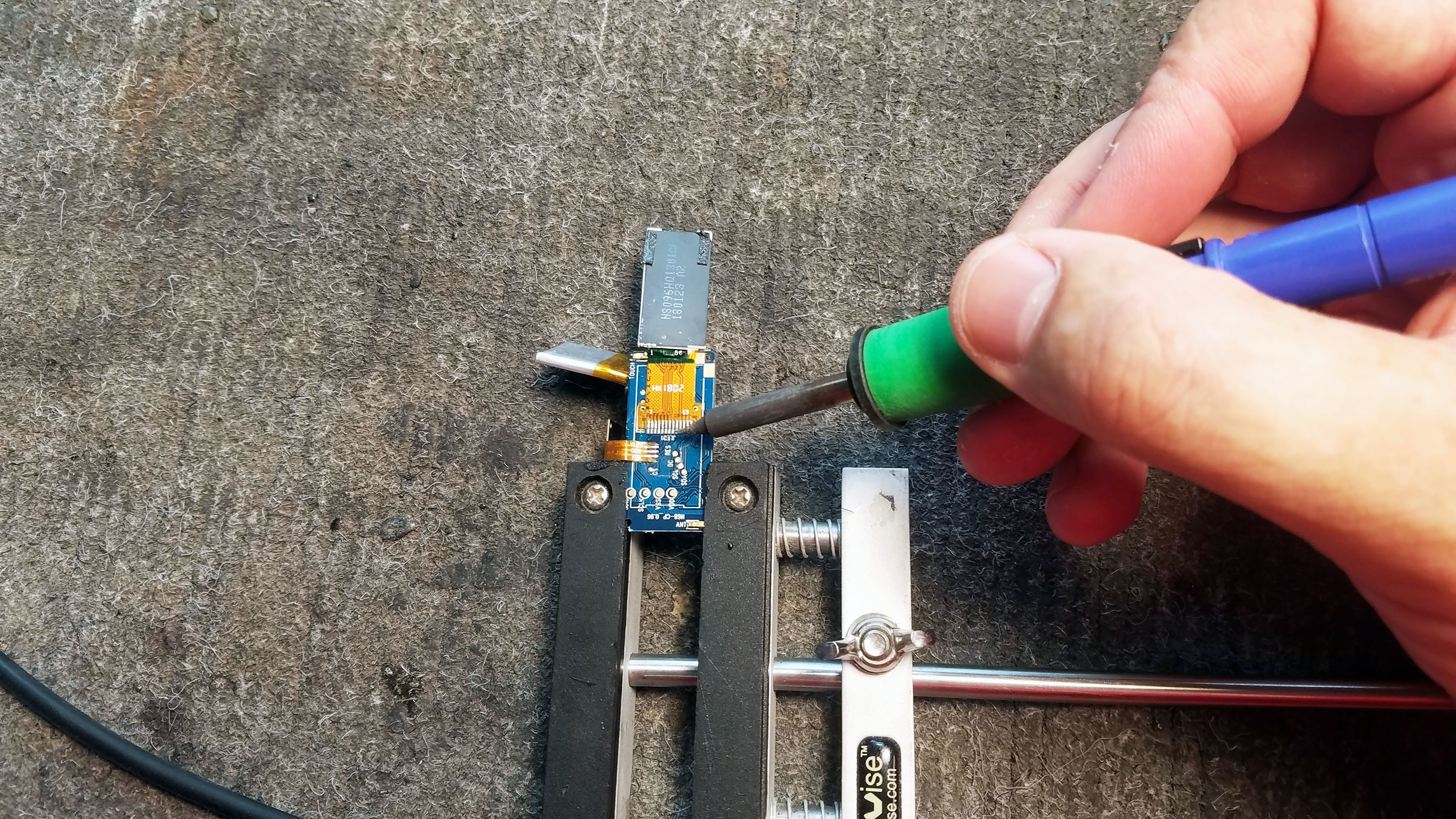
2: Removing the OLED Display
![]()
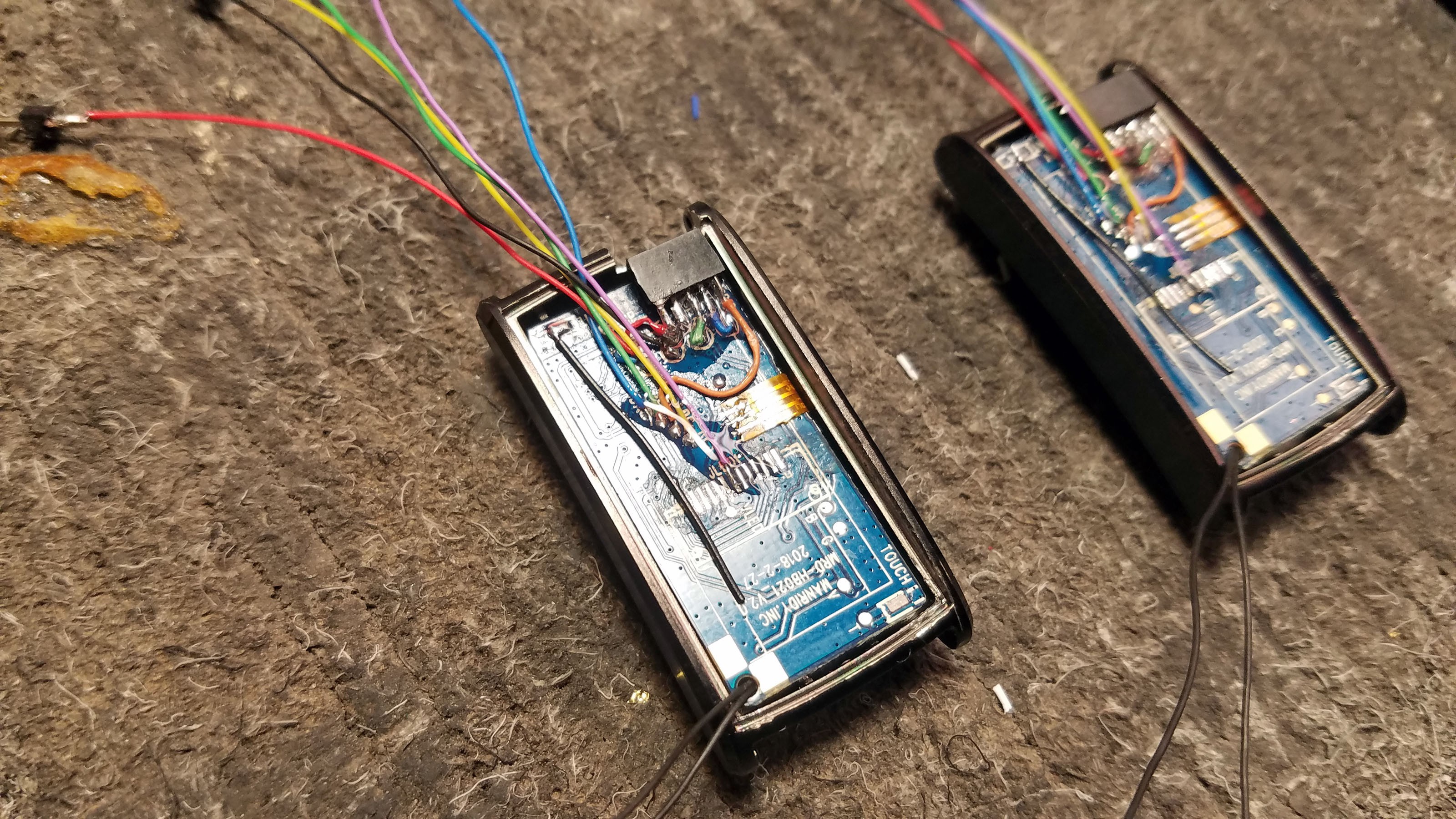
The Tingle does not use the N68's display. It uses up power and space which I would rather devote to sensors and sensor data processing. The display is easily removed with a soldering iron by gently pulling on the display as the soldering iron is played across the display contact area.
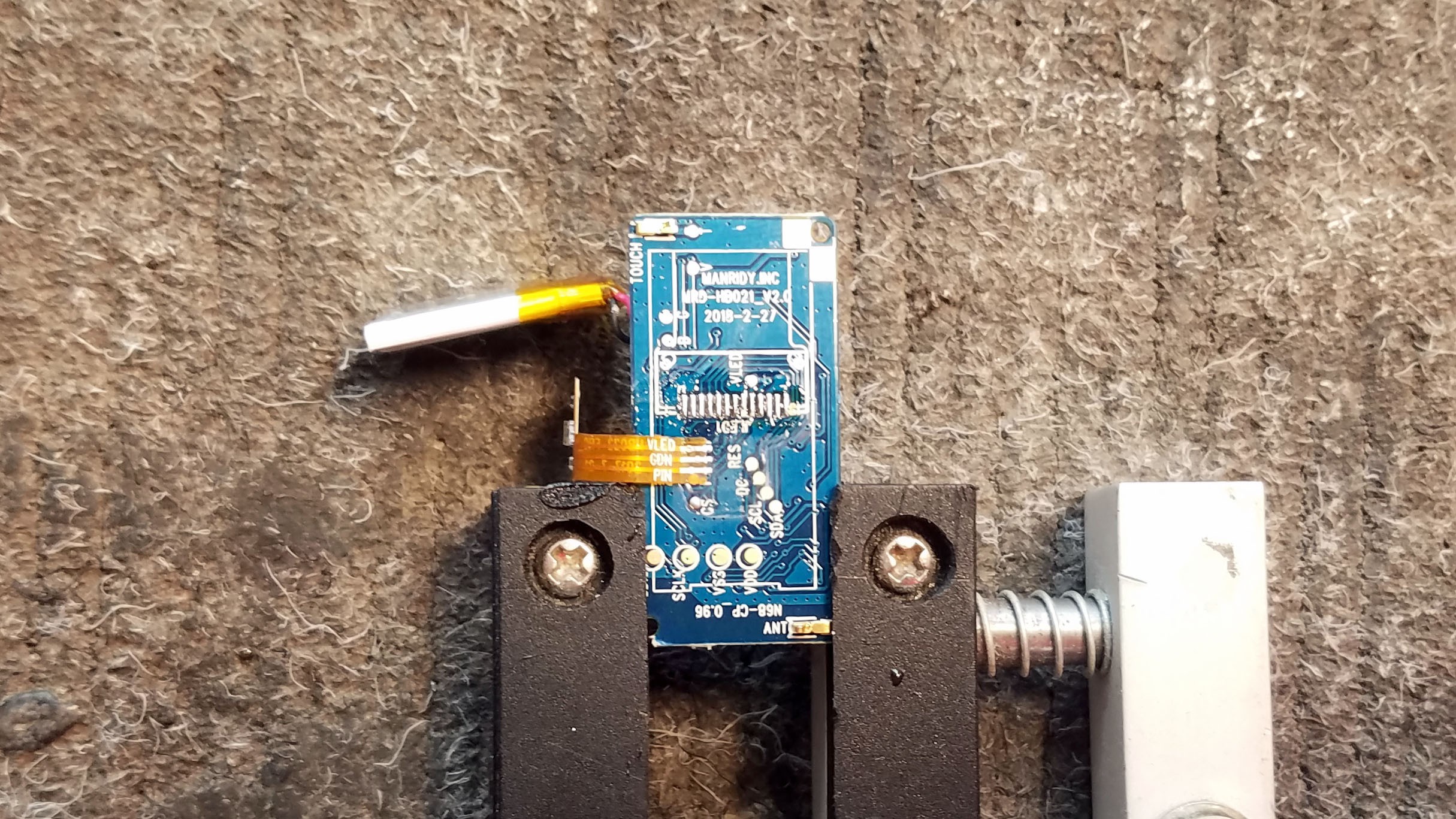
![]()
With the display removed.
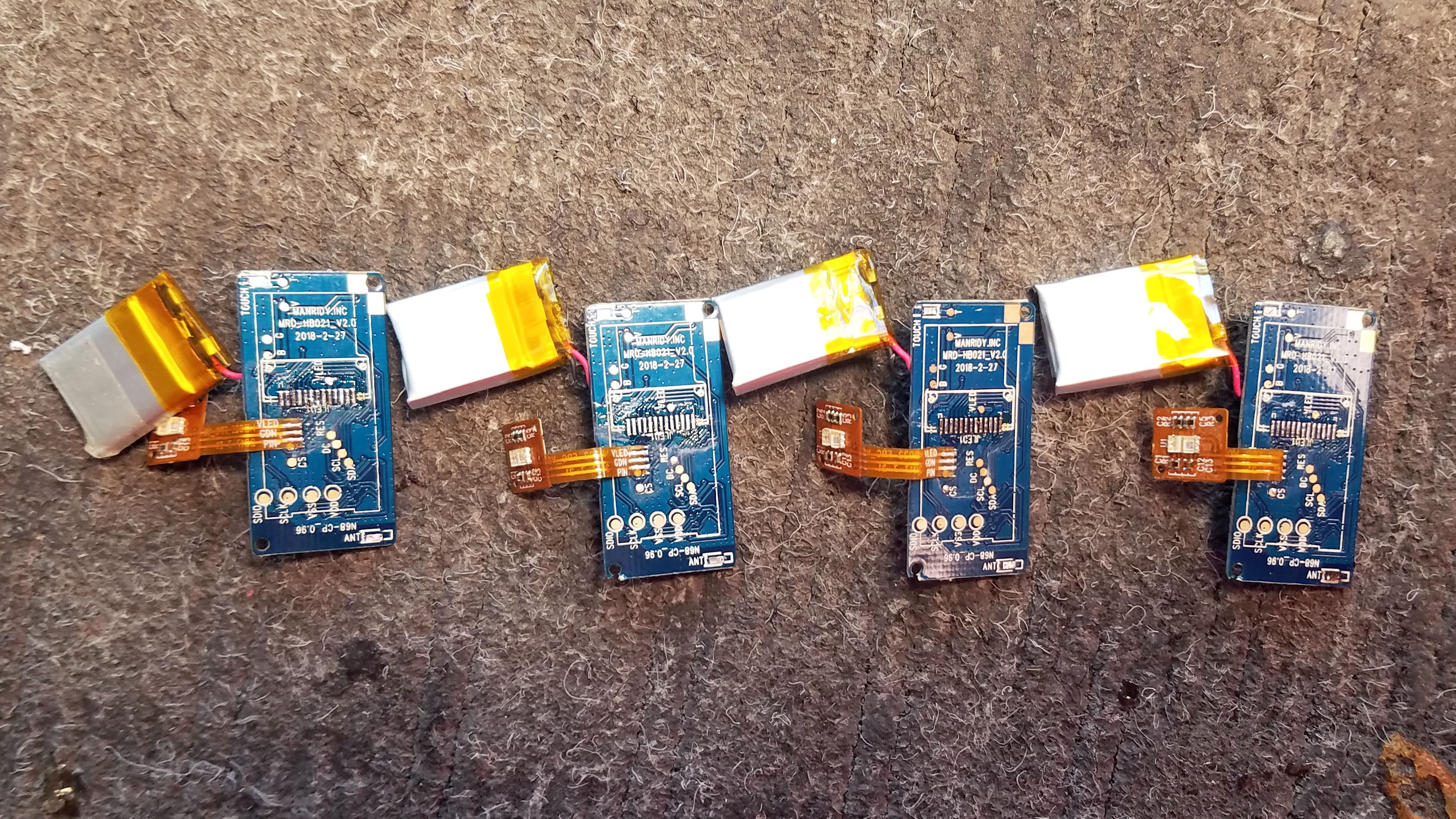
![]()
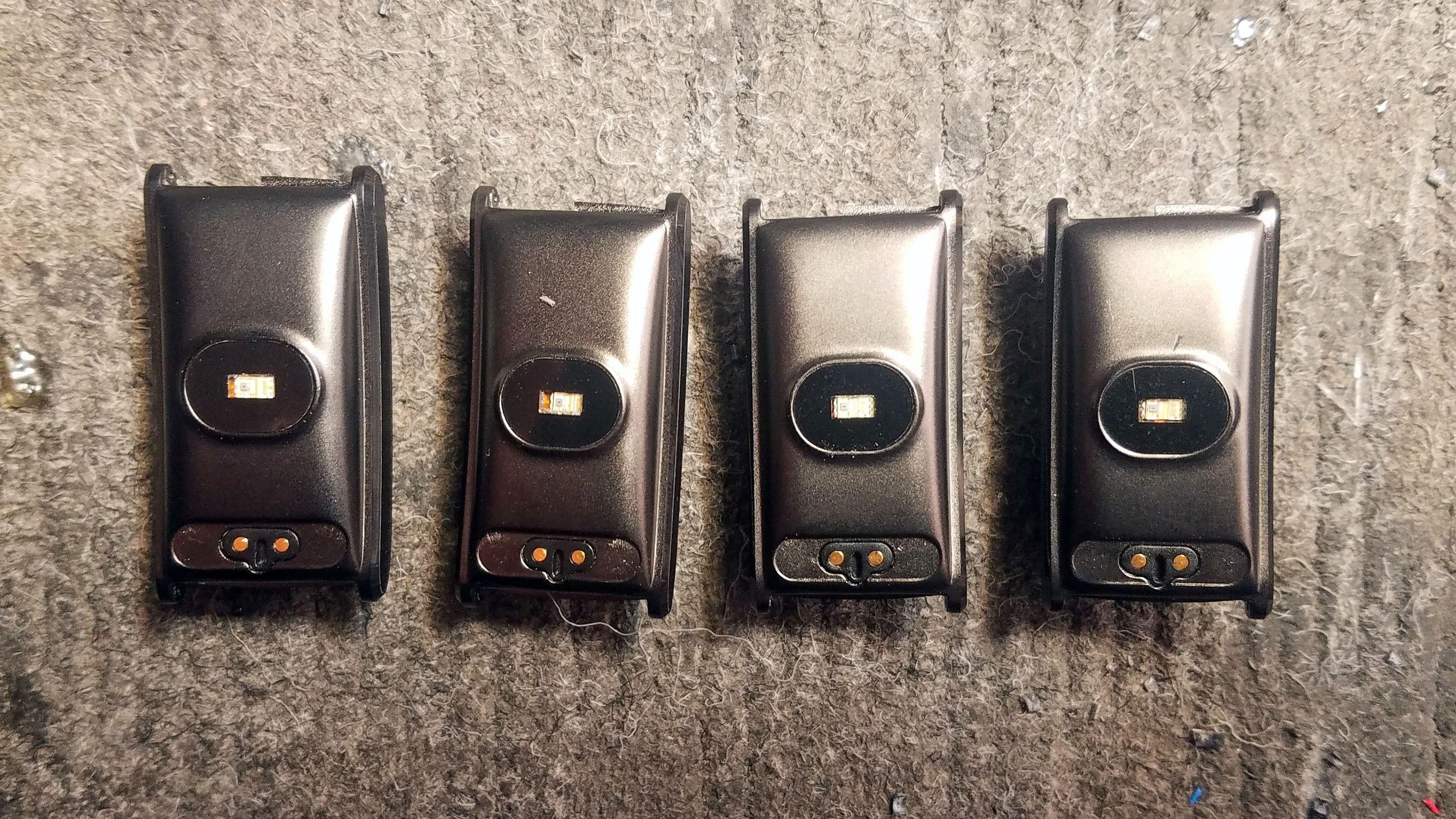
Display removed from all four prototypes.
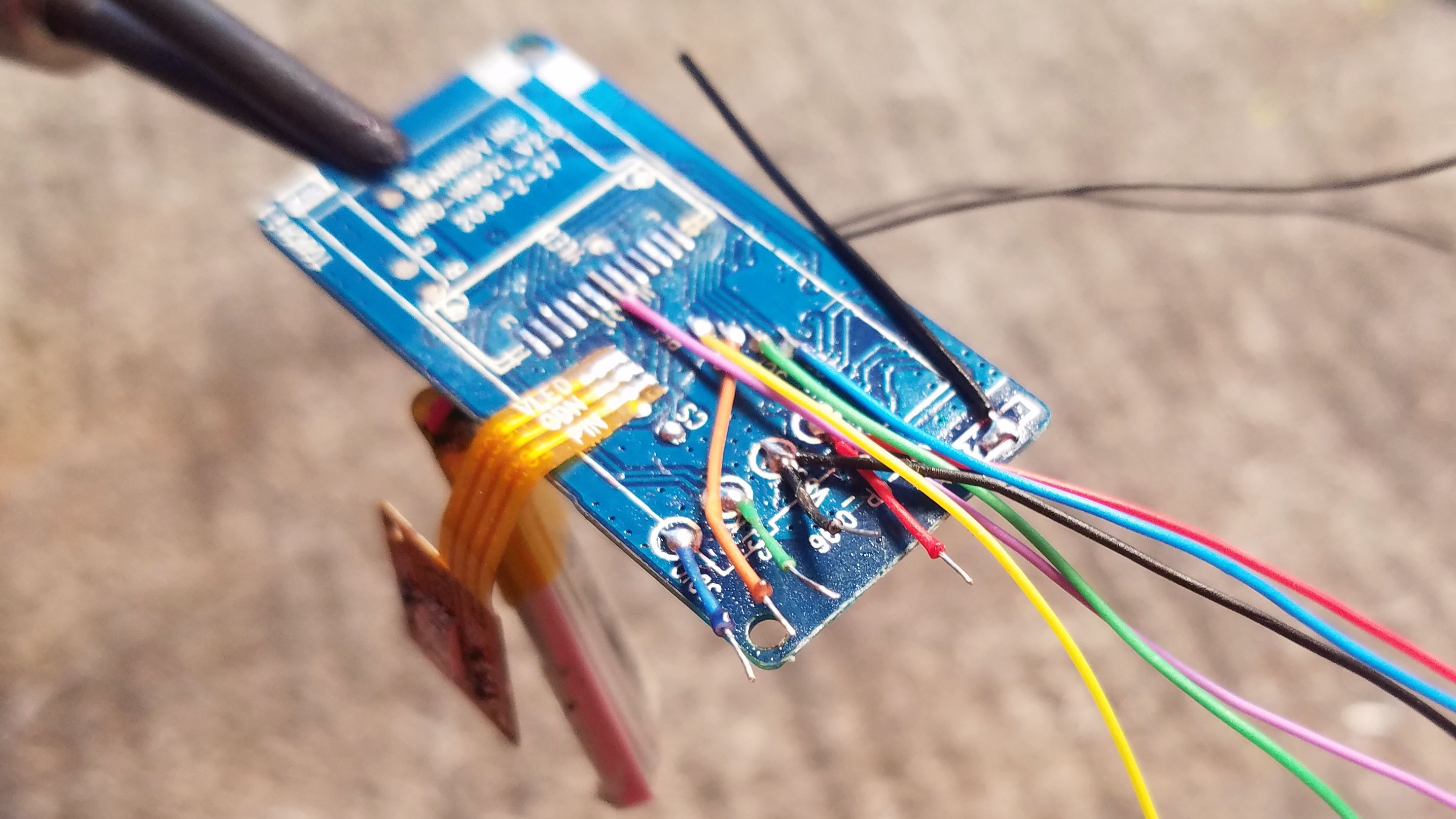
3: Wiring Up the N68 PCB
![]()
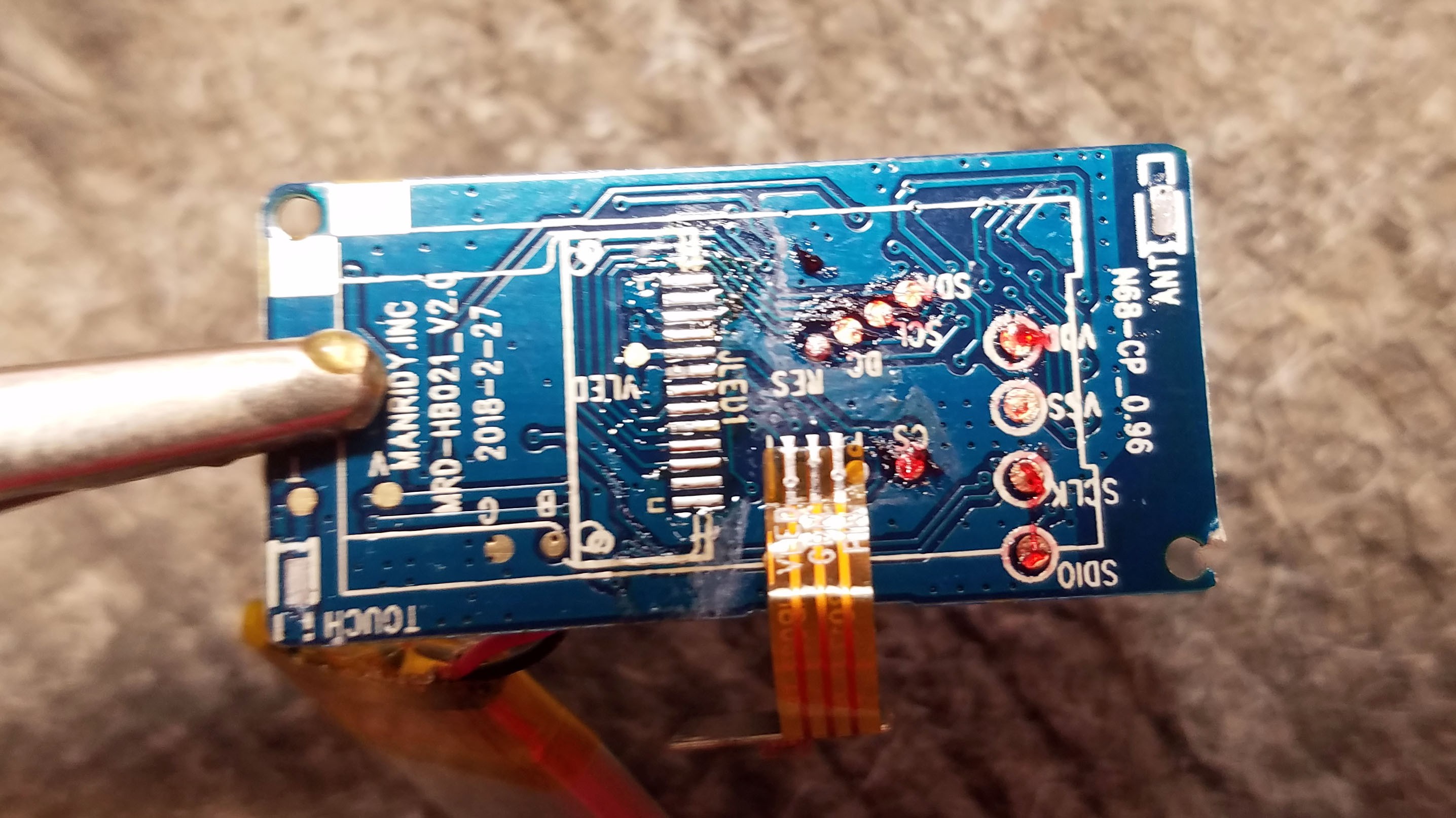
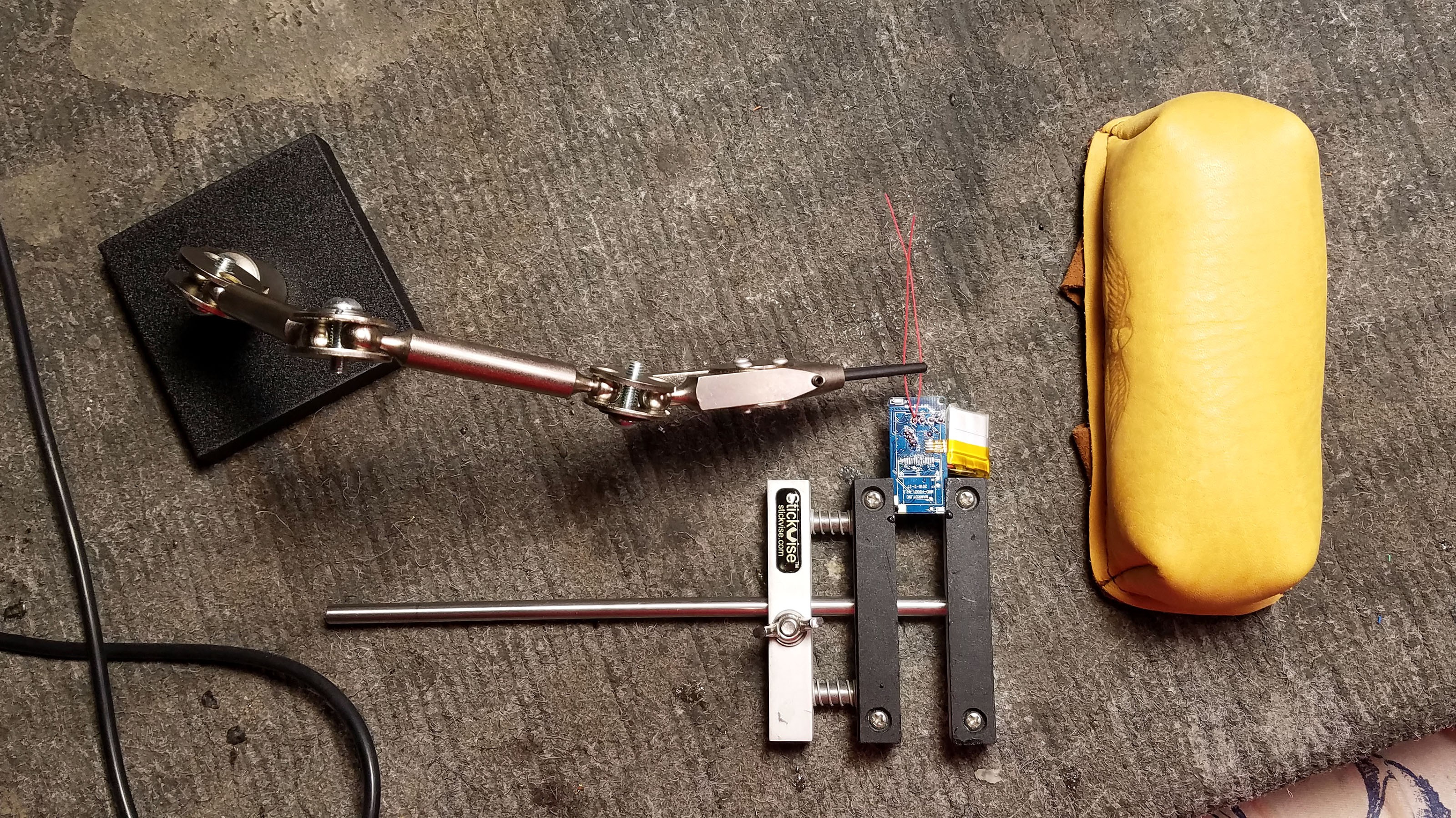
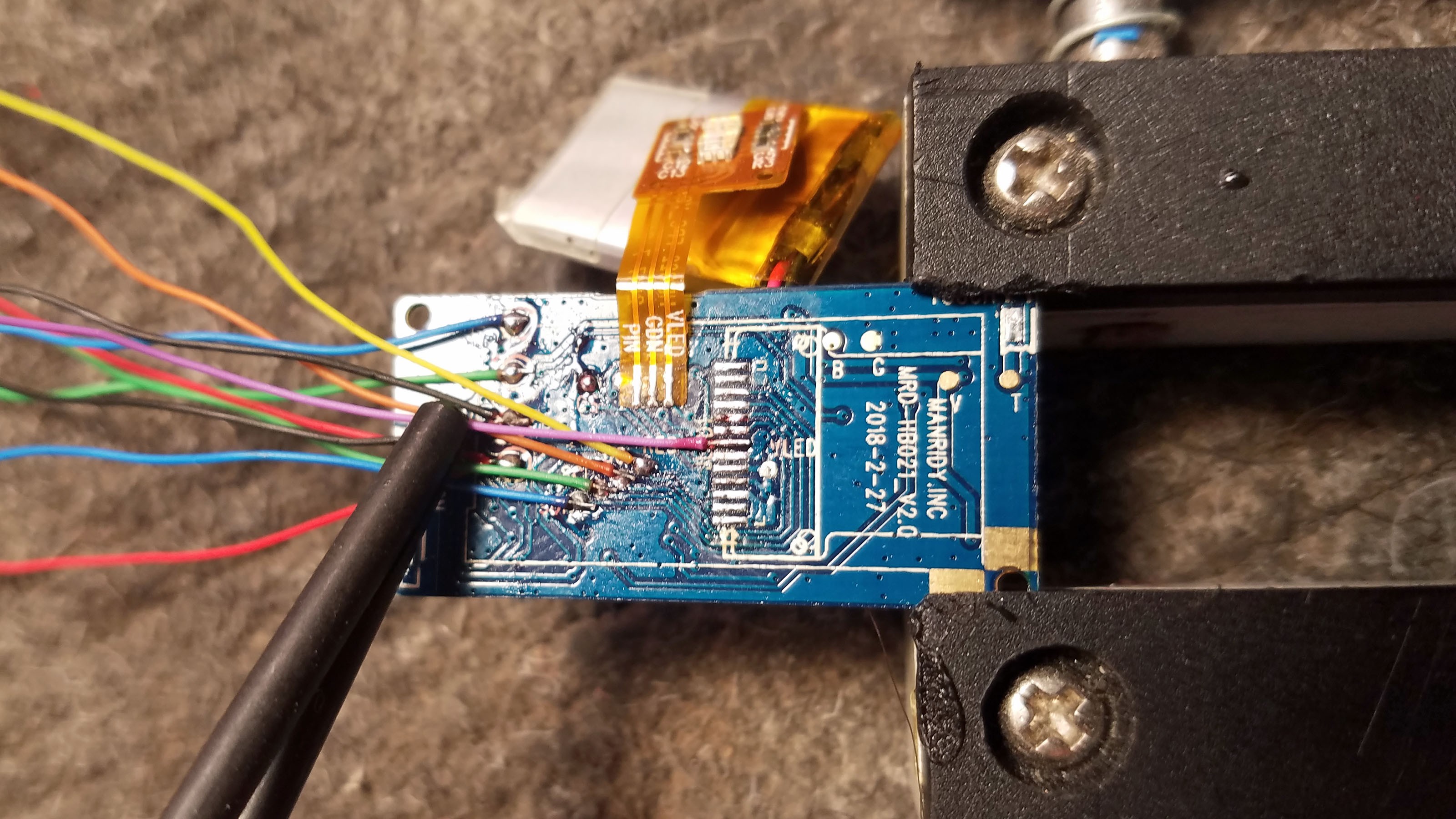
The N68 PCB will have to be connected to the sensor cap, an external programmer and power supply. Conveniently, there are factory test pads which I can solder wires to.
![]()
Fluxing the PCB test pads I will be soldering wires to.
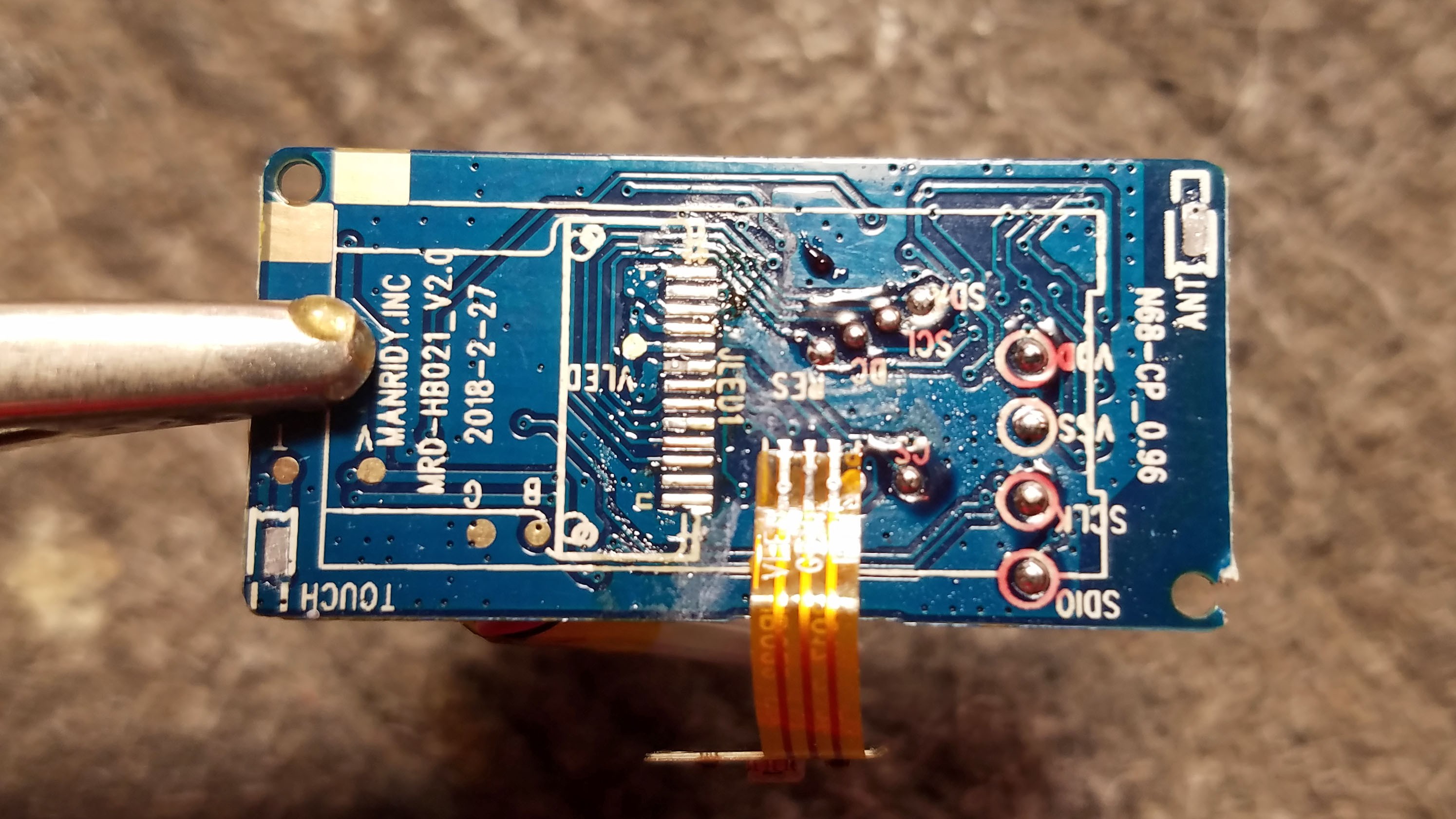
![]()
Pre-soldering the test pads to make soldering easier + stronger.
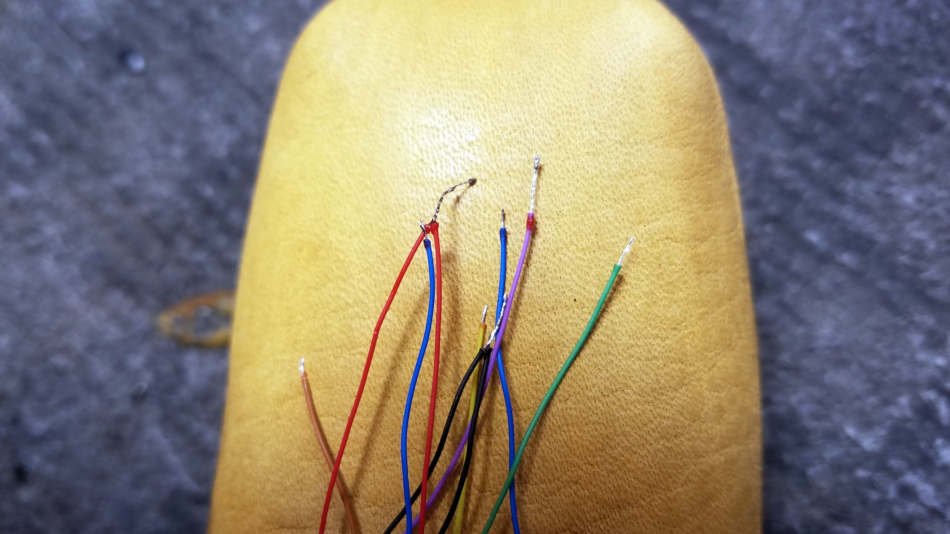
![]()
Fluxing and pre-soldering the ends of the wires I will be using.
![]()
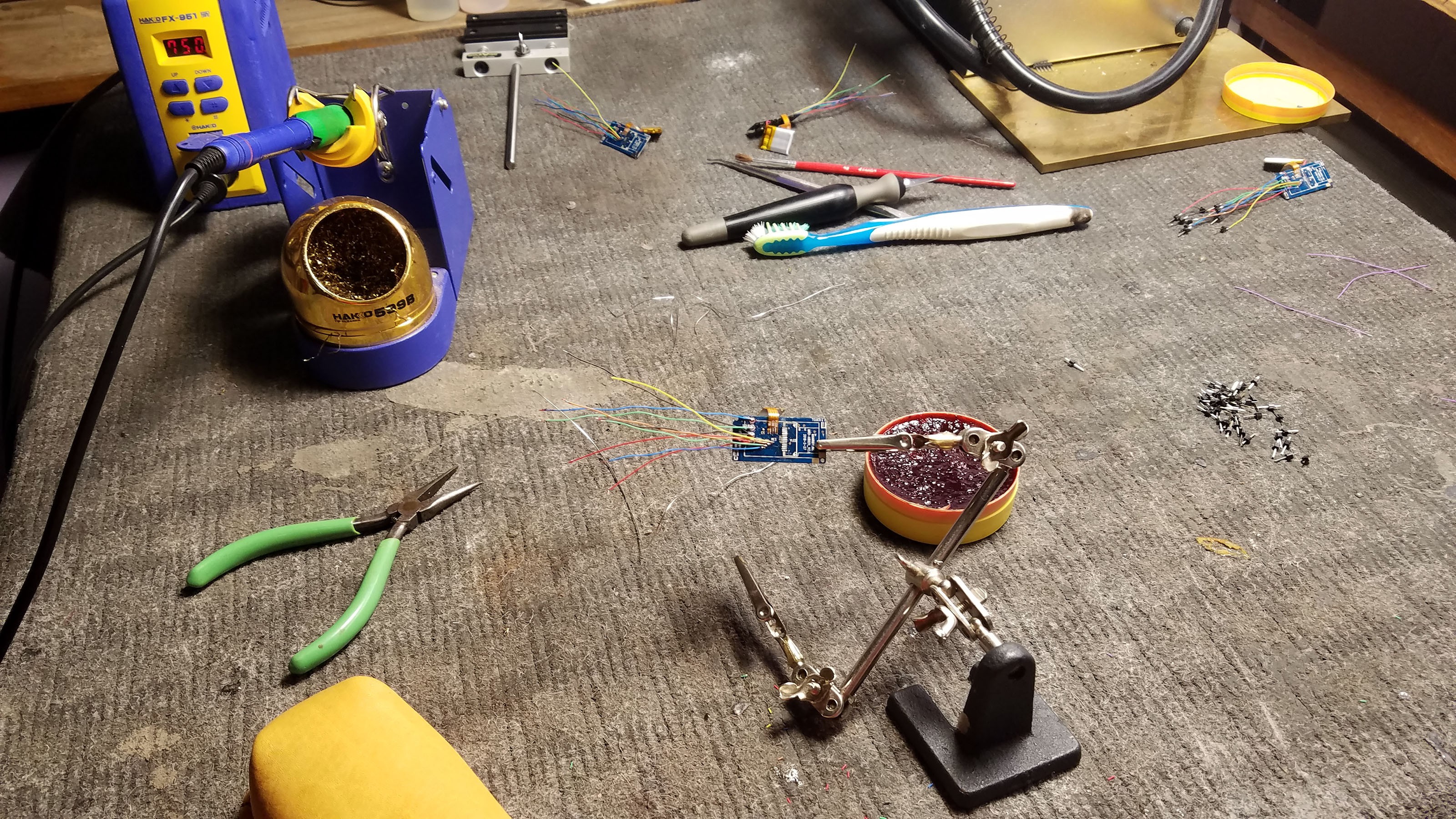
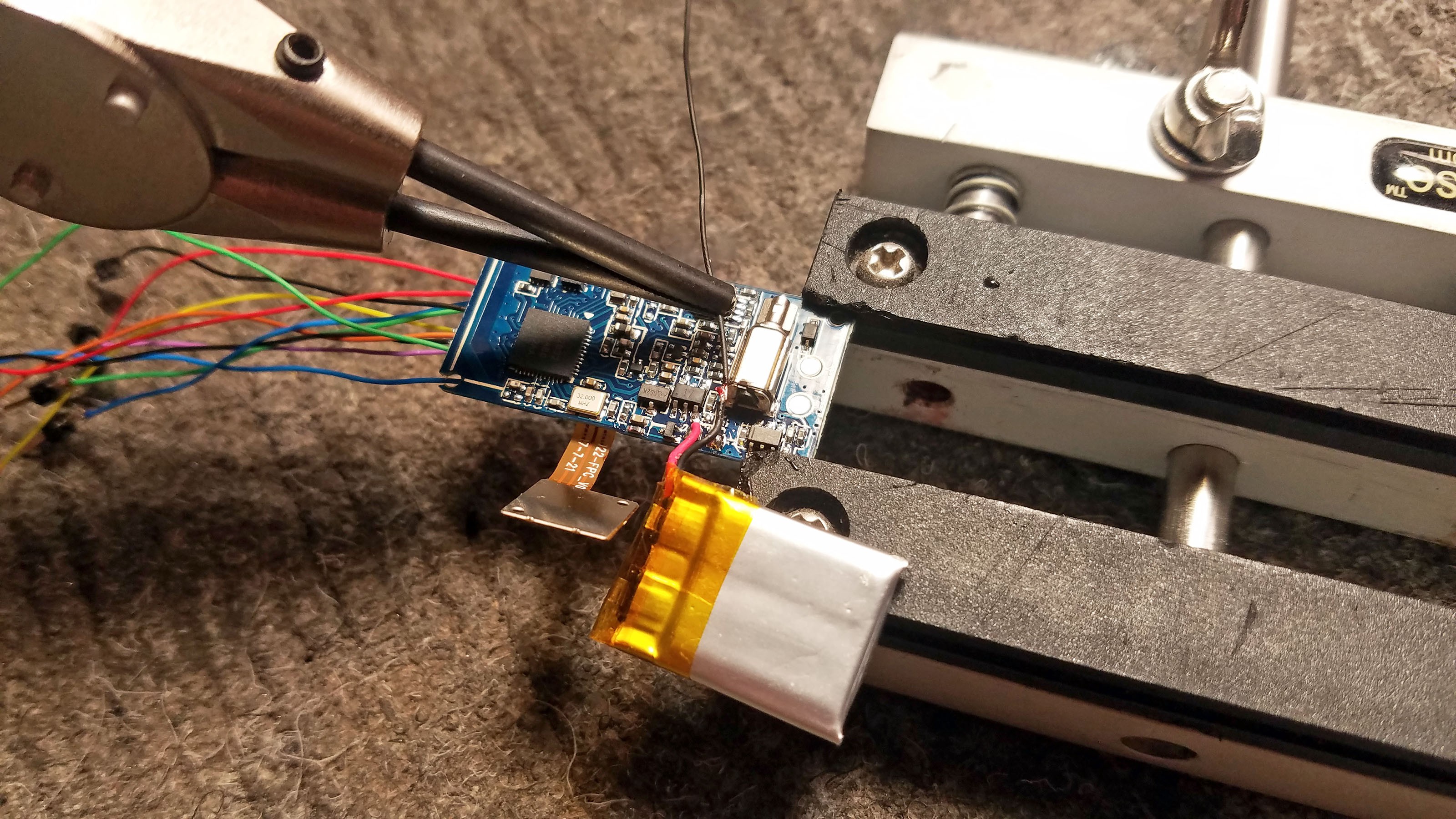
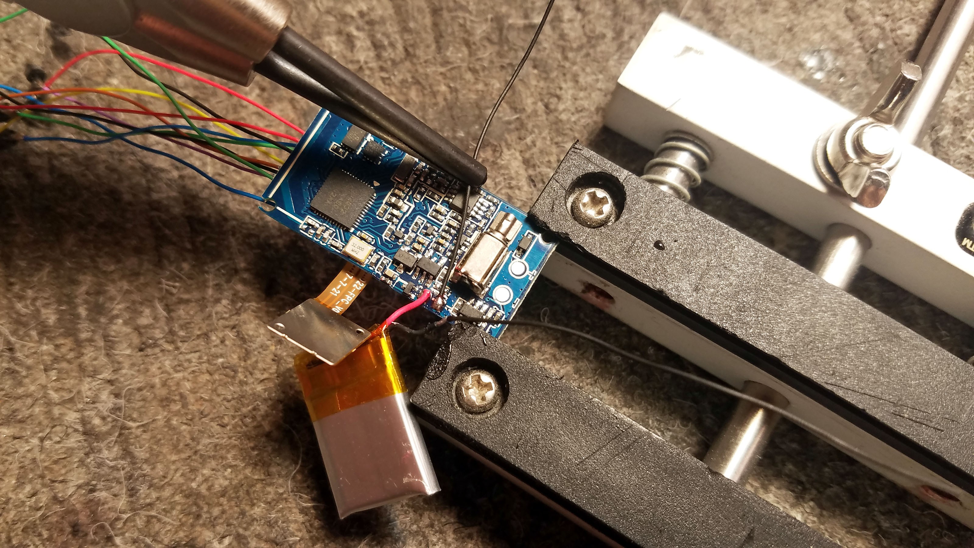
My soldering setup. I have a pretty nasty hand tremor so everything has to be setup as if I'm going to do it one handed. That way I can brace my right hand with my left while also resting my right hand on the above leather sand bag.
![]()
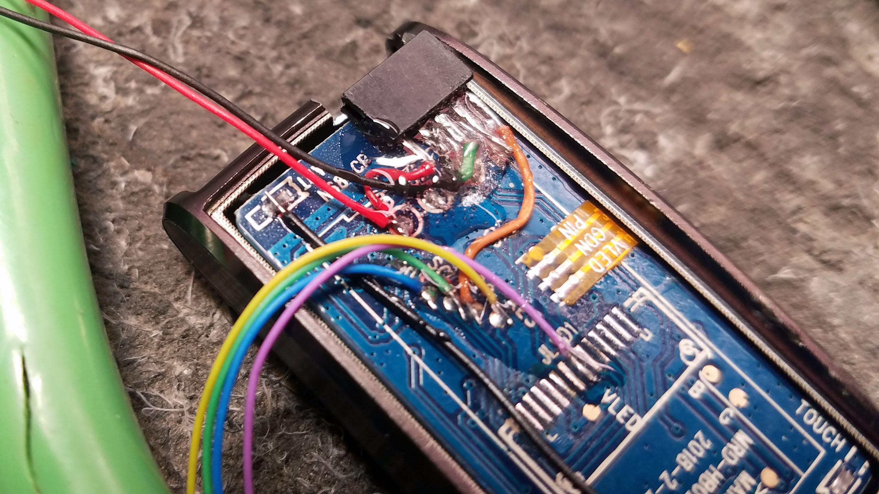
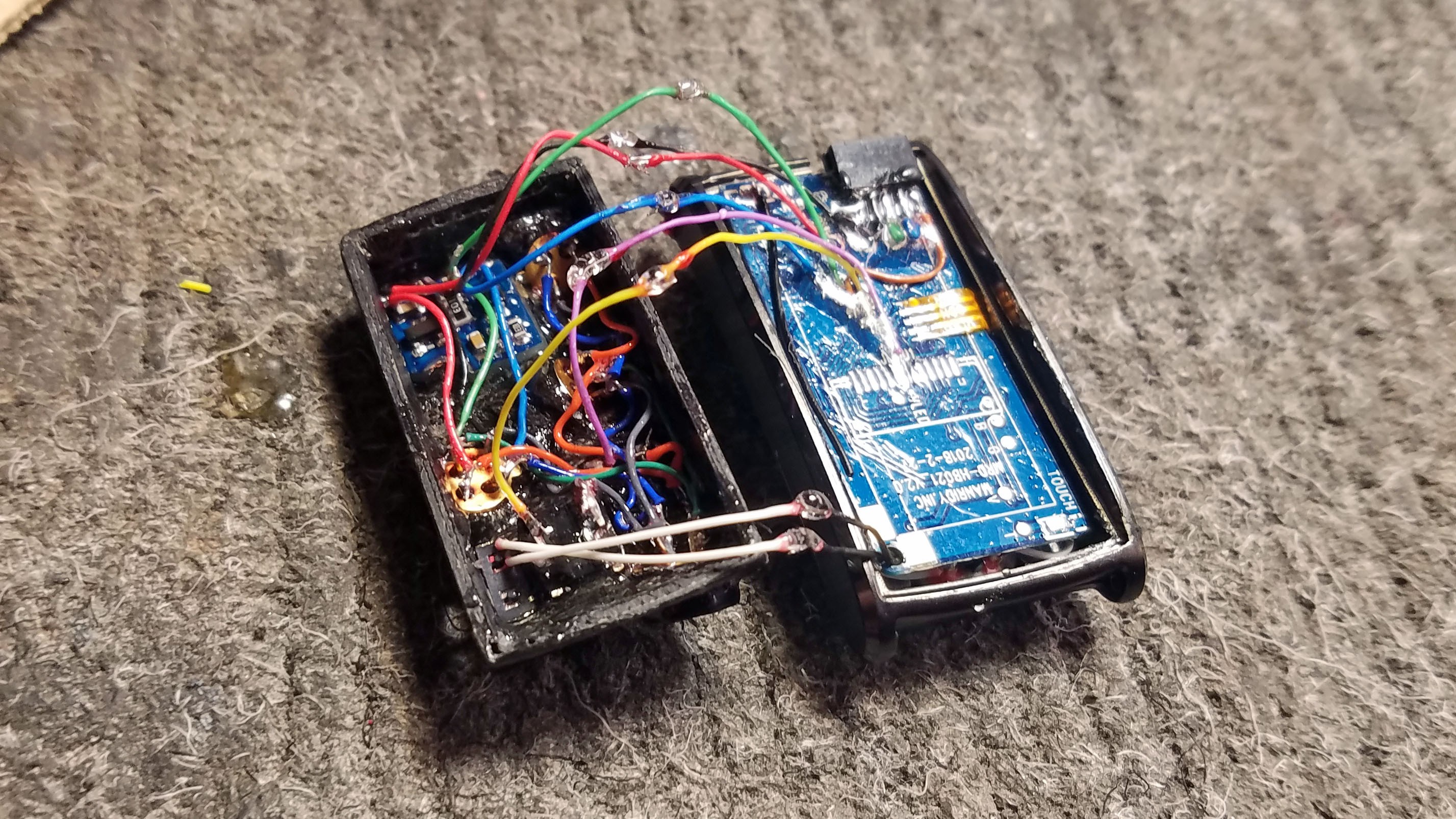
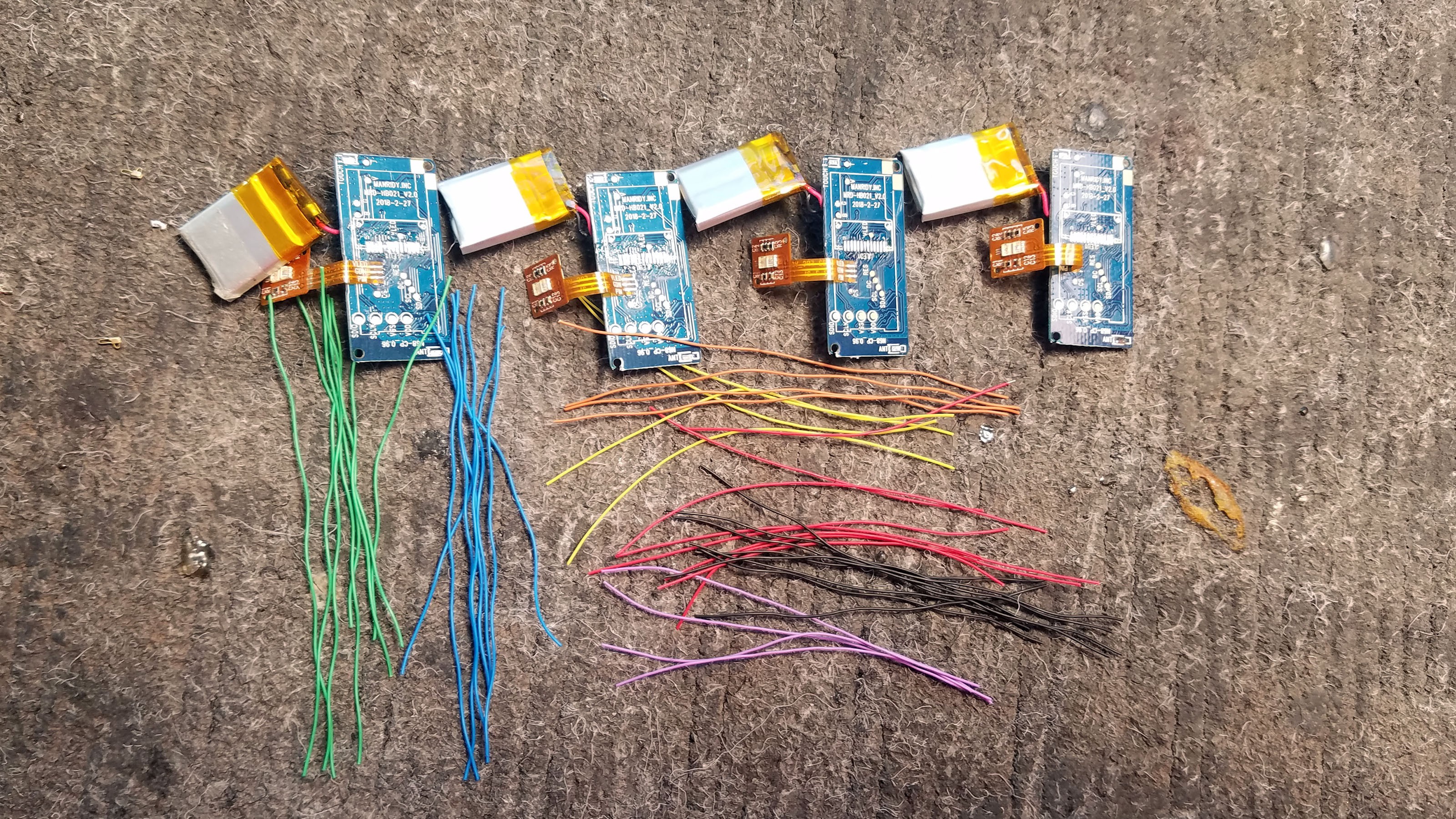
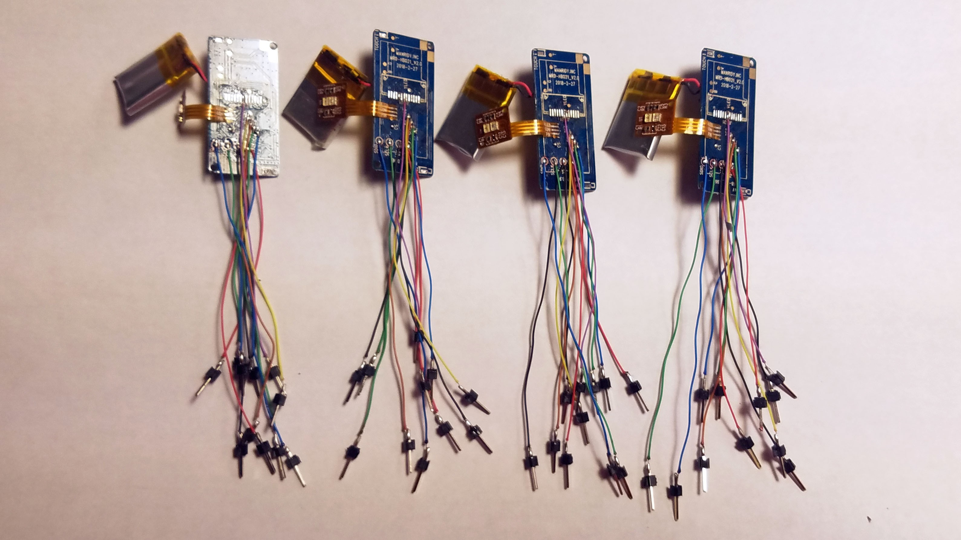
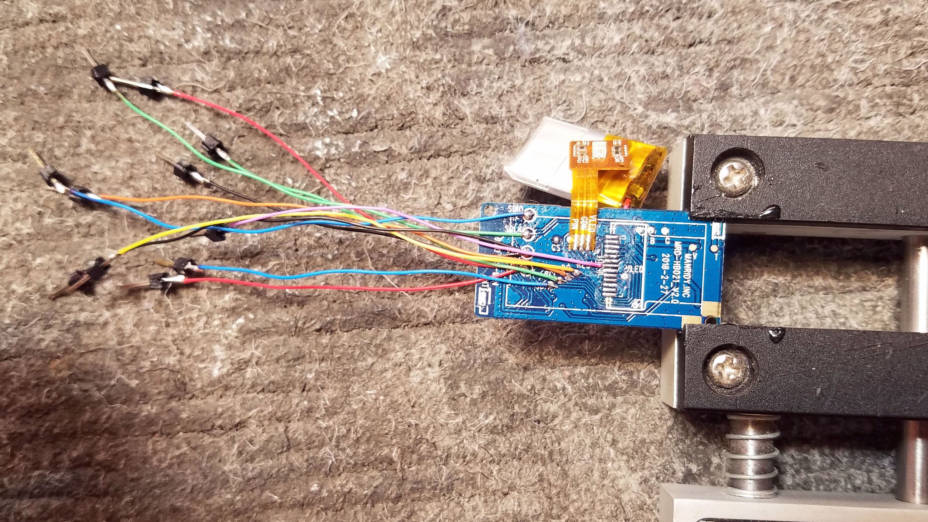
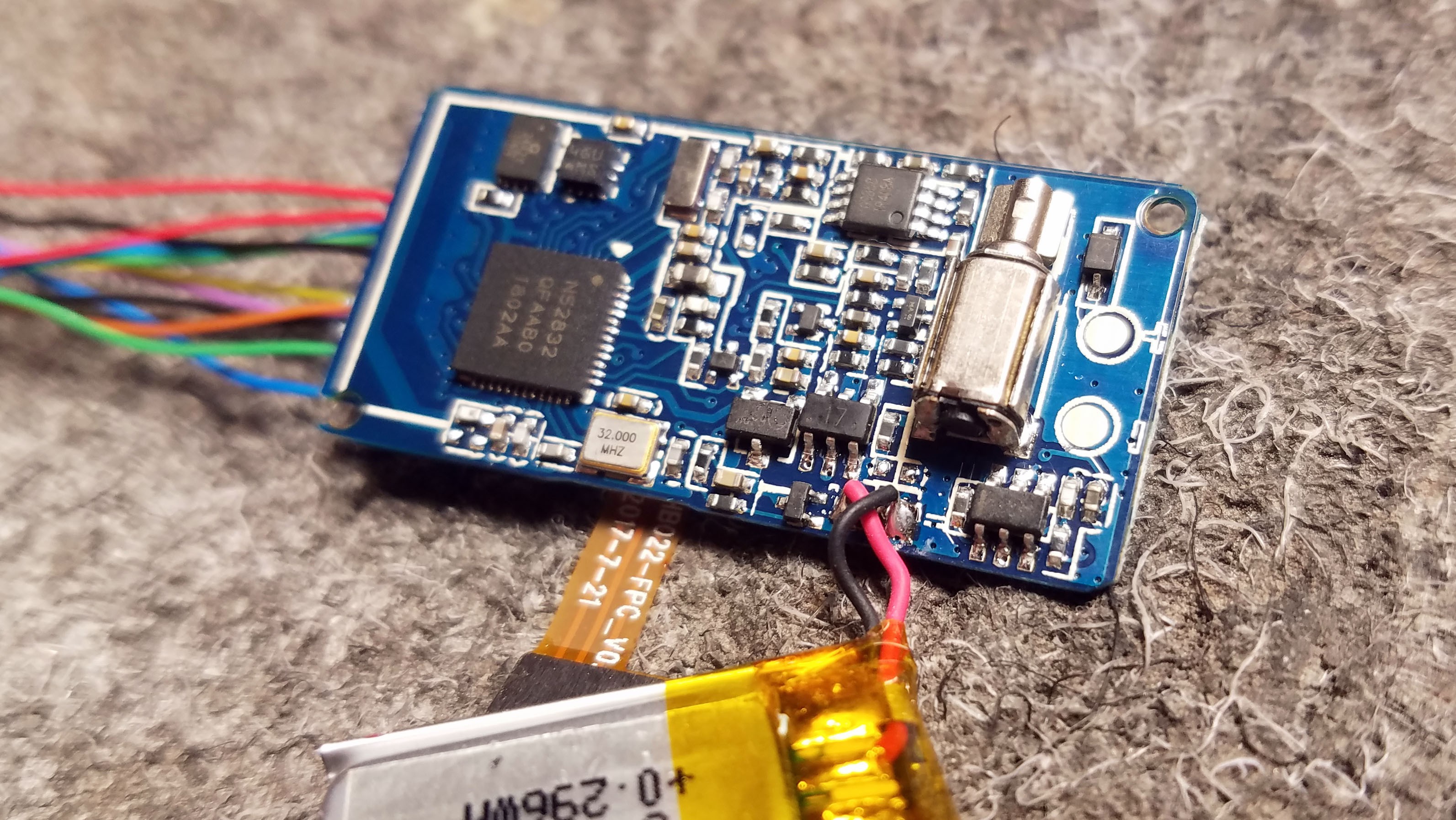
All the wires have been soldered on.
Red: 3V
Black: GND
Top Blue: SDA for I2C
Top Green: SCL for I2C
Bottom Blue: DIO for SWD programming
Bottom Green: SCK for SWD programming
Yellow: Button on sensor cap
Brown: Serial UART TX or Misc. GPIO for external adapter.
![]()
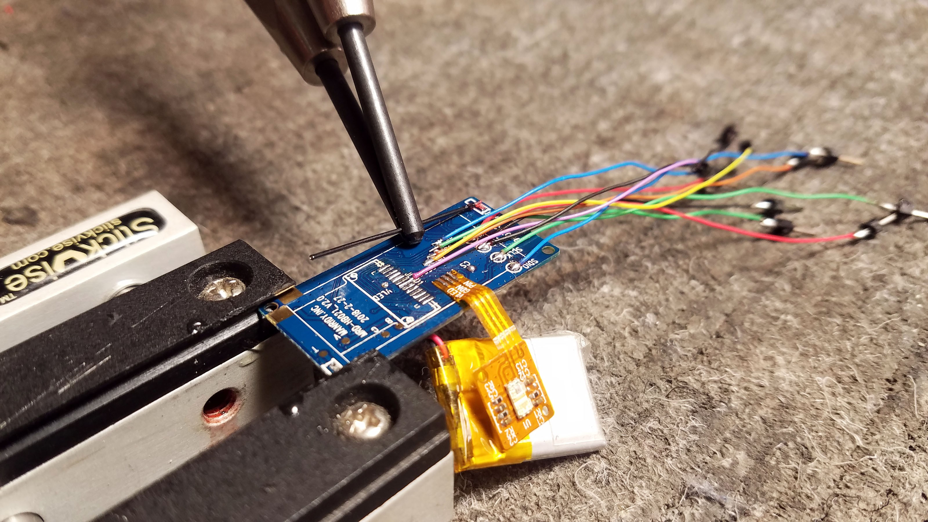
This last purple wire is kind of tricky. It recycles a GPIO that was used by the display but which is not easily accessed with a test pad. The puple wire controls the LED on the sensor cap.
![]()
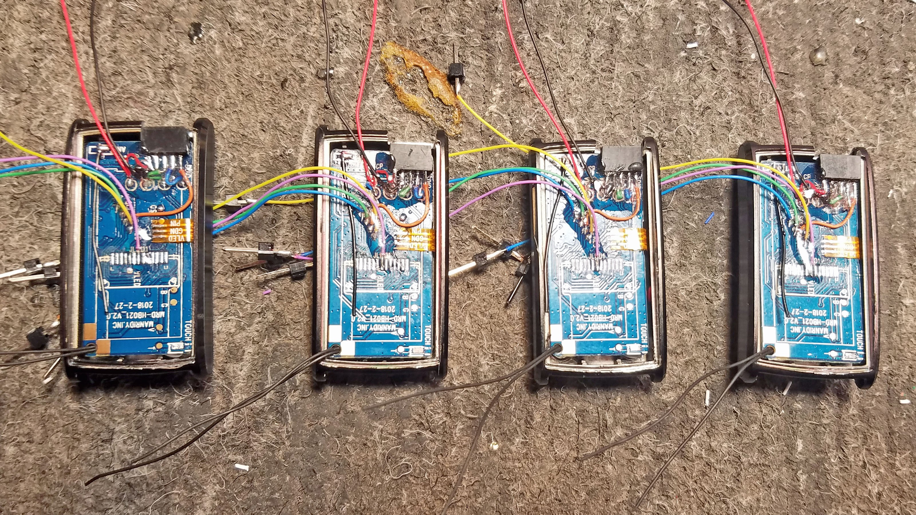
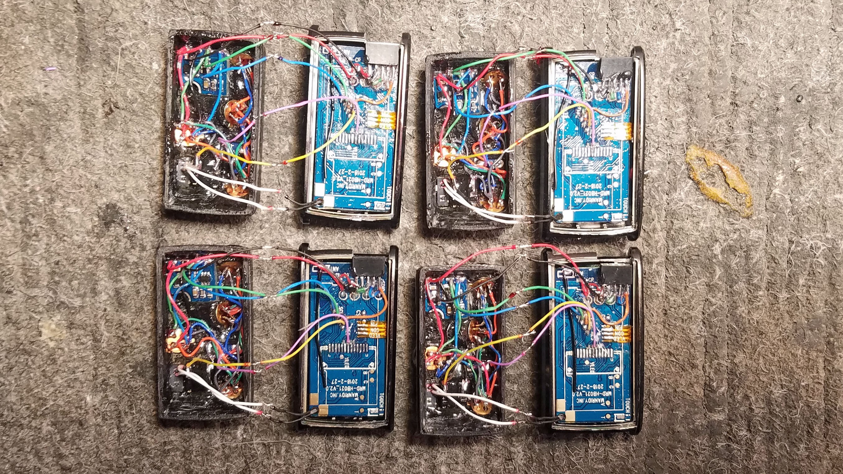
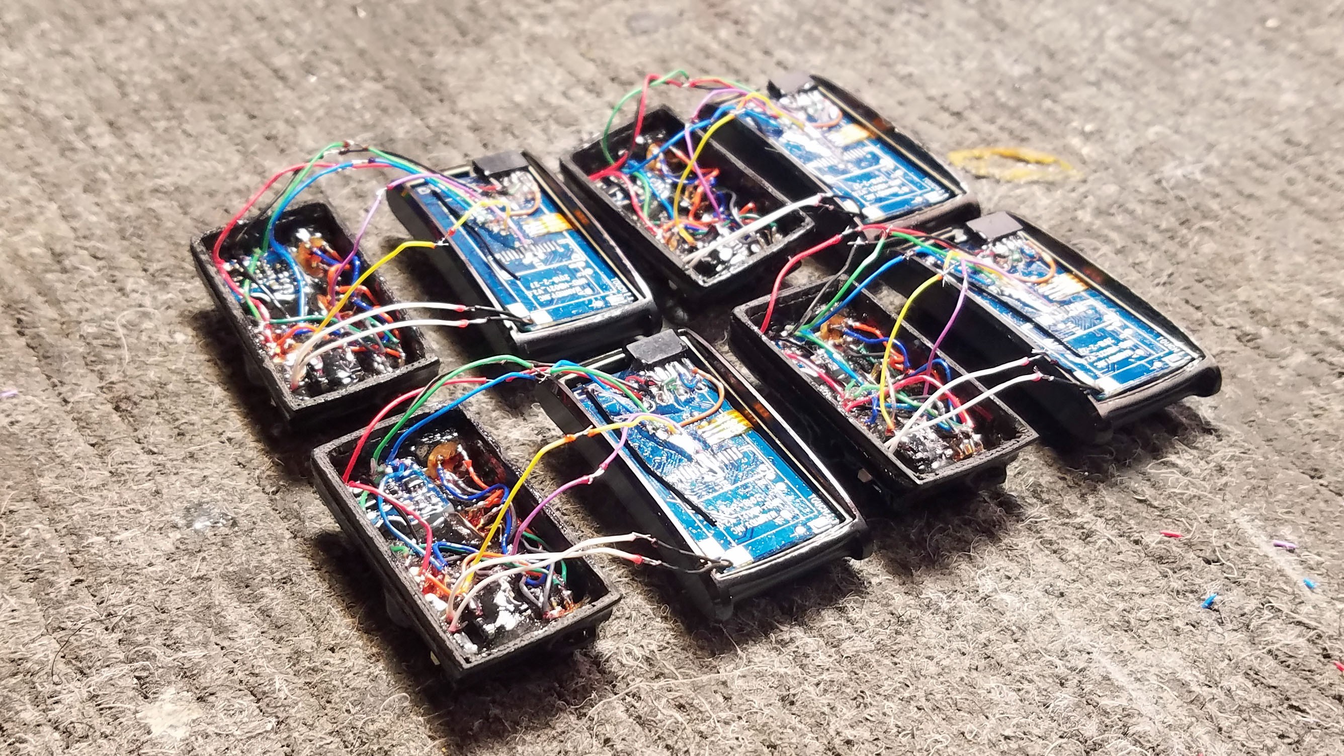
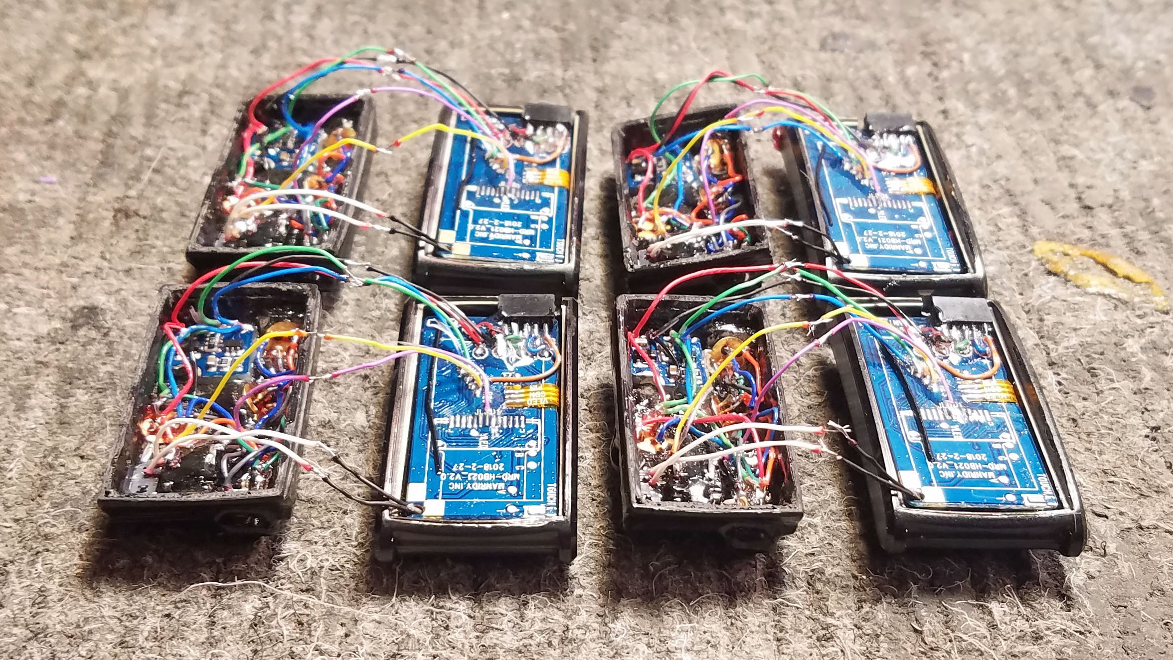
Once all the wires are soldered to the board I solder header pins to the other ends this is necessary for testing, something that is extremely important to do at multiple stages since there is so much hand soldering in play.
![]()
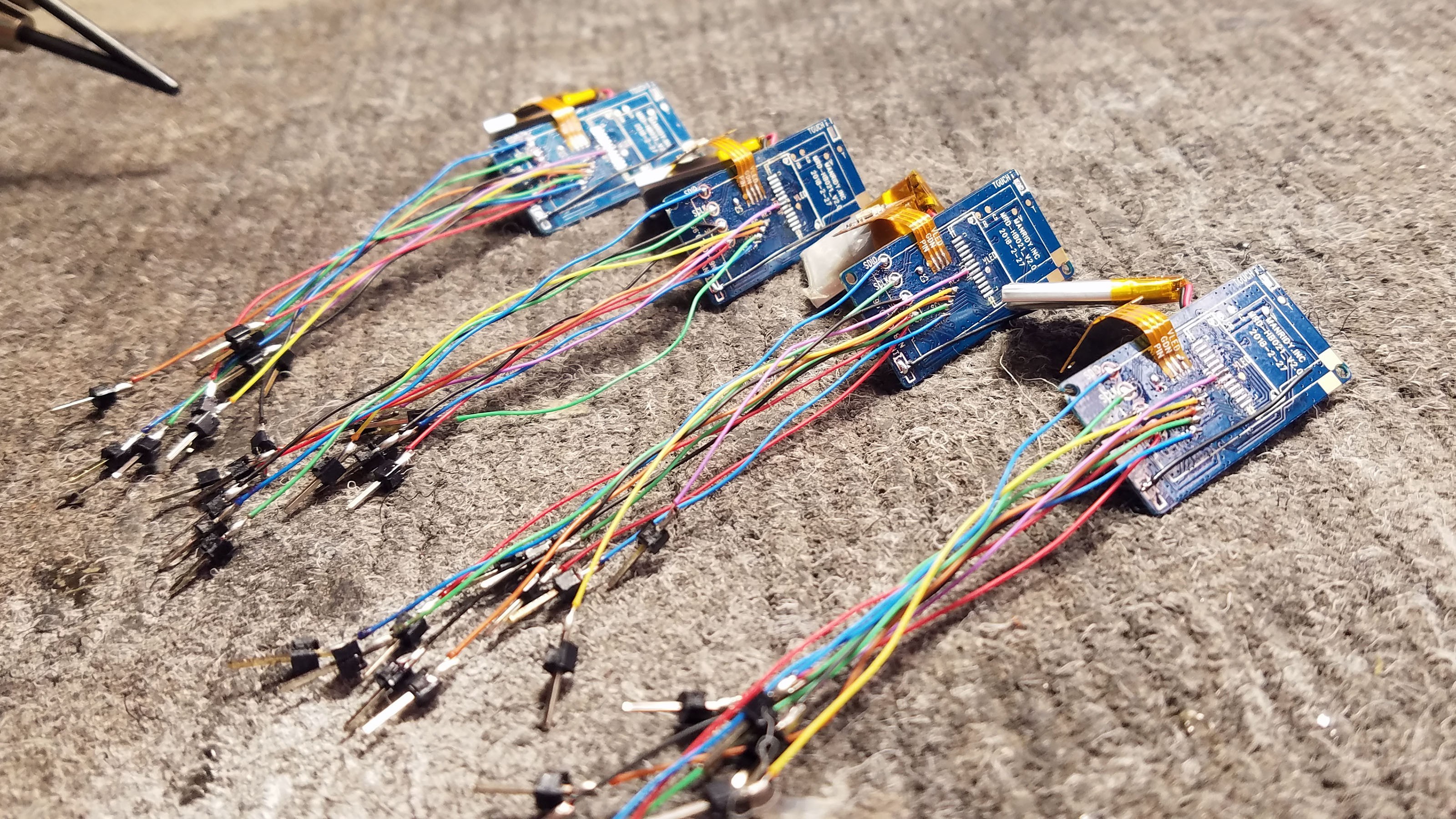
Finished with wiring up the N68 boards! (for now at least).
4: 3D Printed Sensor Cap Fabrication
![]()
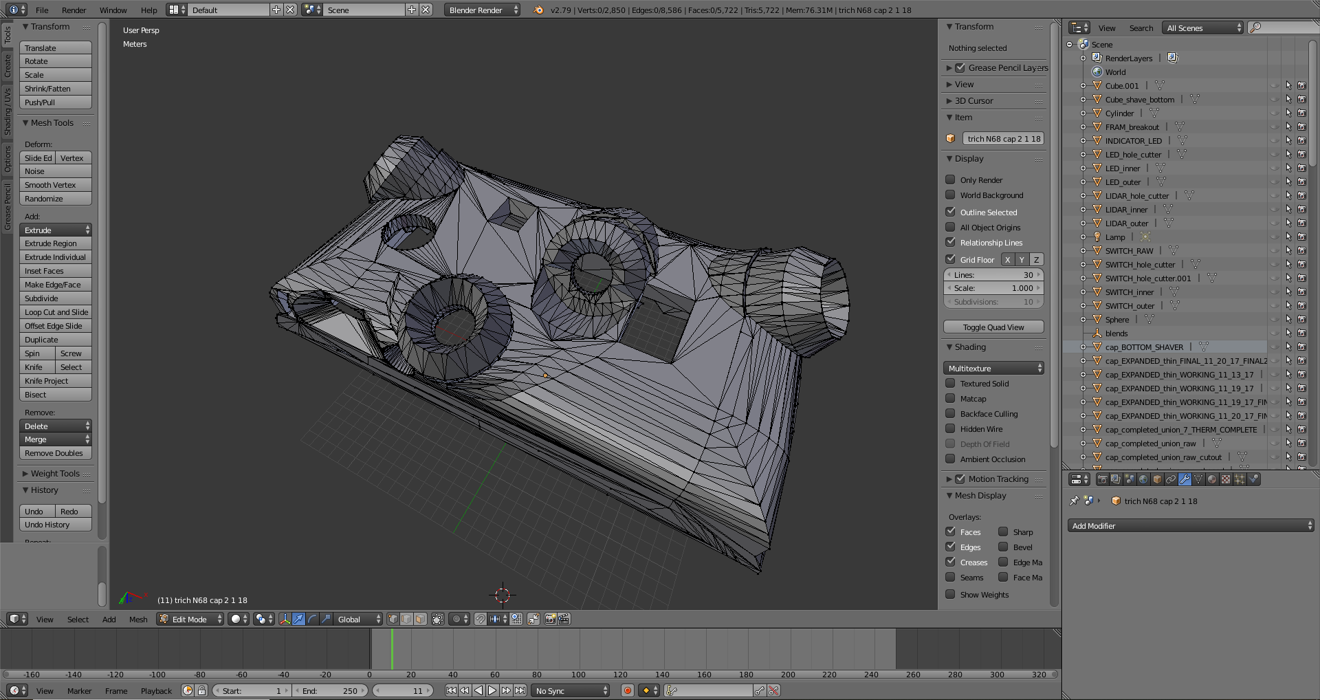
The sensor cap is where the magic happens. This is where the Tingle really sets itself apart from other attempts and gesture recognition feedback for compulsive disorders. Tingle really leverages the strengths of 3D printing. The angles and placement of Tingle's sensors are crucial to its function on an individual basis. In addition, all the sensor placements have to be exactly the same across prototypes, both to make the machine learning models work and also for research data collection. 3D printing allows for complete control over sensor position, plus the ability to rapidly iterate and test various sensor configurations. The above is the Tingle sensor cap model in Blender, the software I used to create it. The sensor cap model can be found in the Tingle project Github repository.
![]()
The inside of the cap has been modeled so that all the various components will slide into place exactly where they are supposed to go.
1a: MLX90615 Thermal sensor 1
1b: MLX90615 Thermal sensor 2
1c: MLX90615 Thermal sensor 3
1d: MLX90615 Thermal sensor 4
2: VL6180 distance sensor
3: LED
4: Button
5: Power switch
![]()
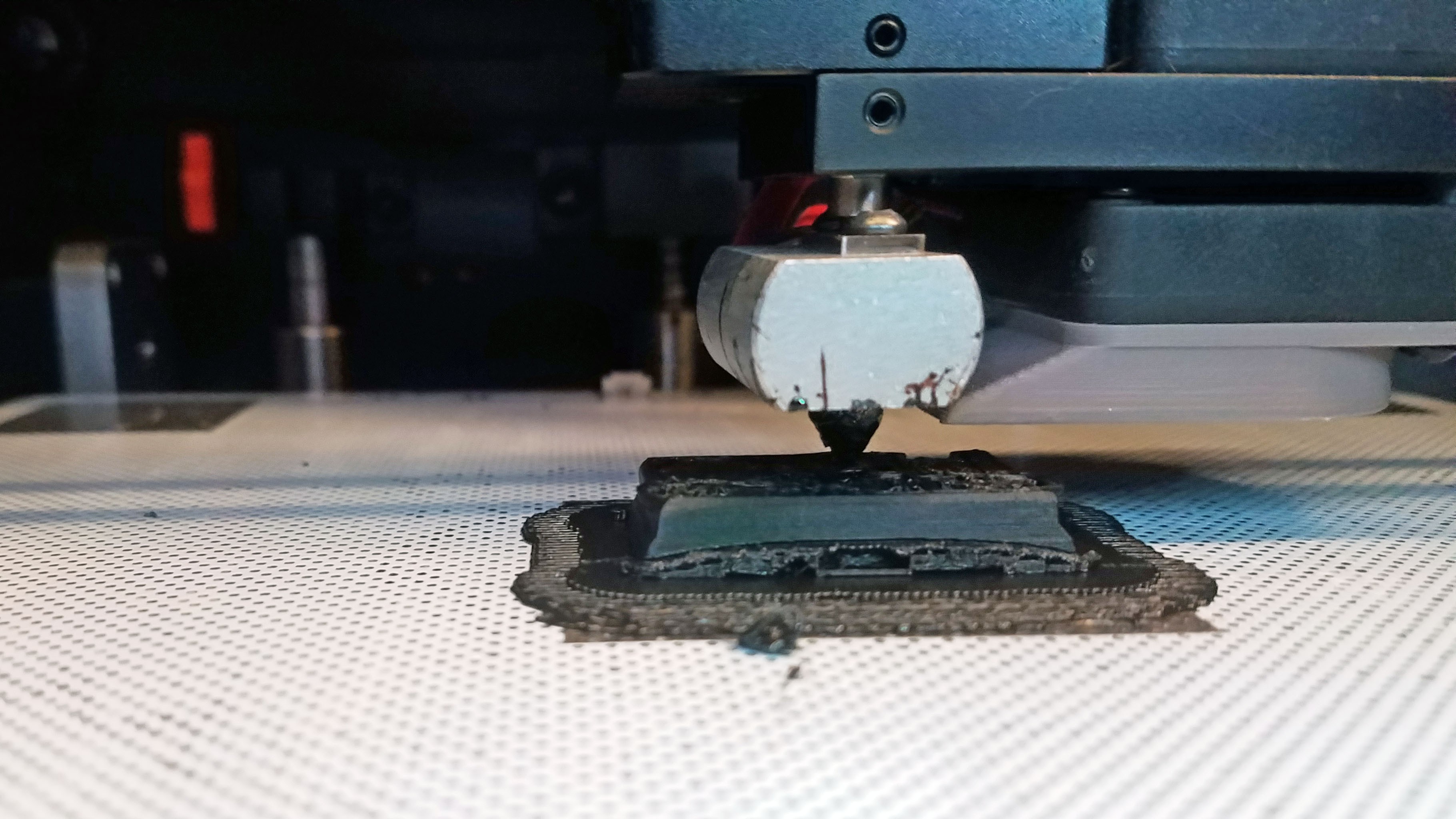
Sensor cap being printed on a Zortrax M200 3D printer in black ABS plastic.
![]()
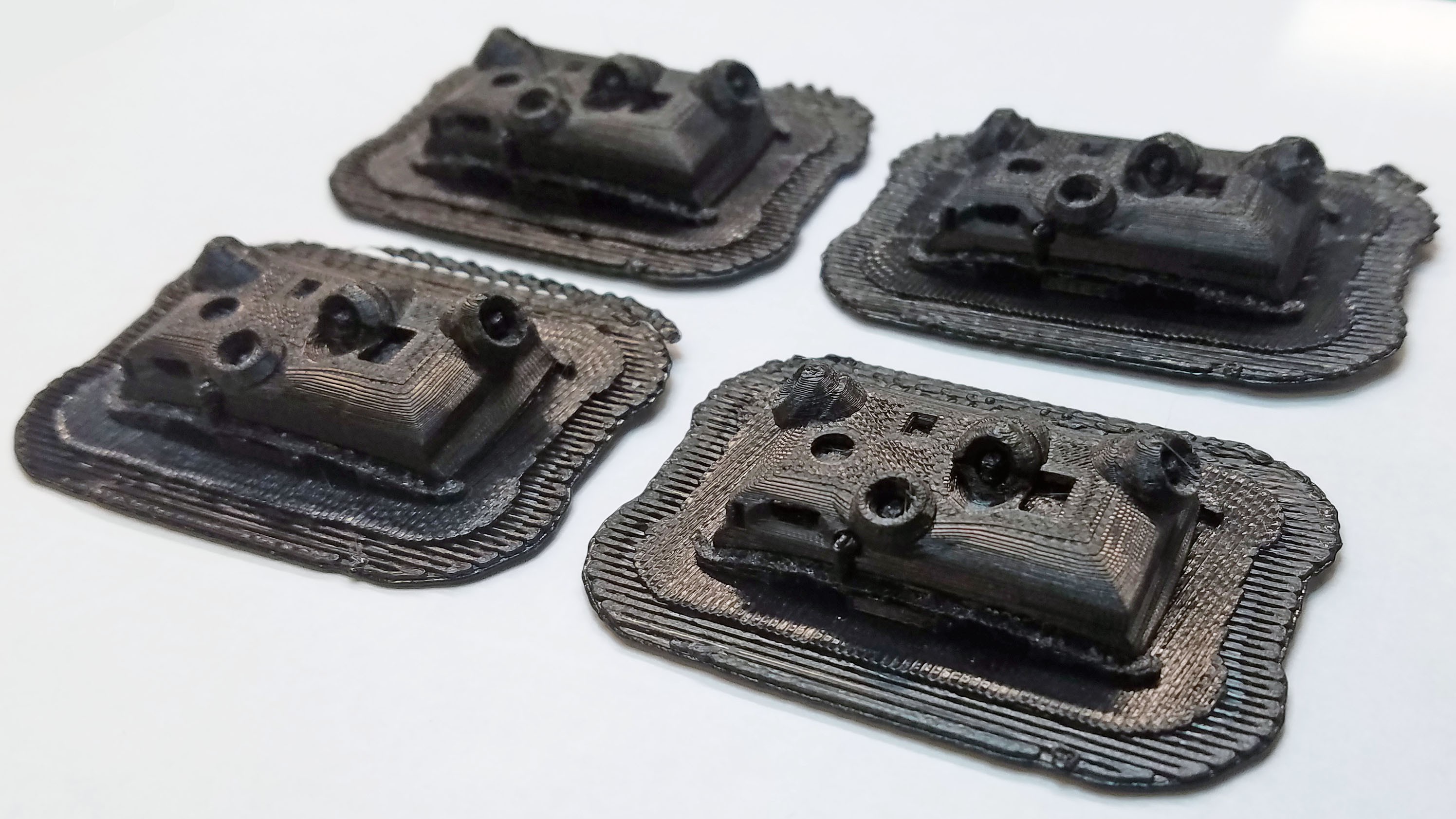
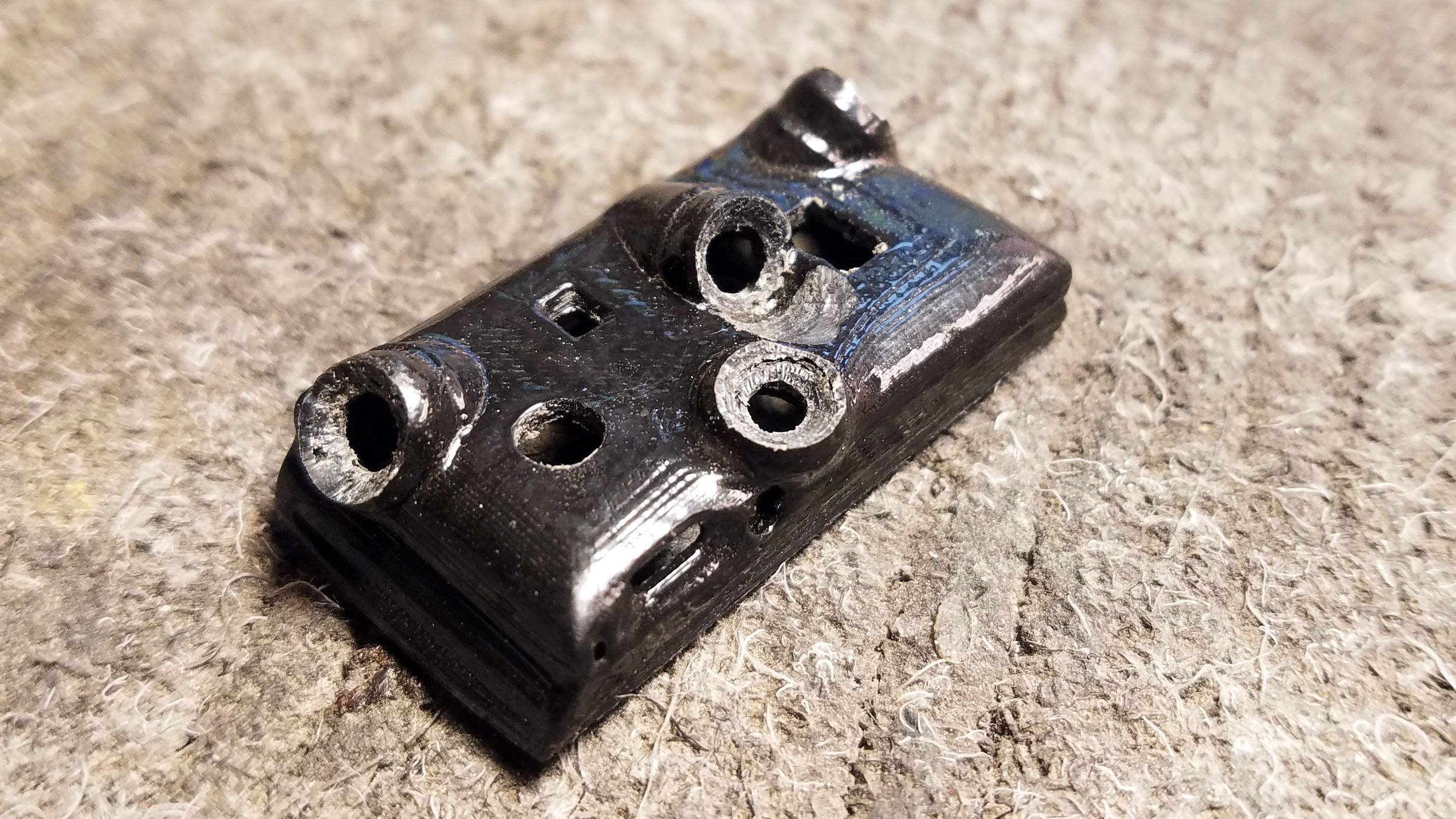
This is what the sensor cap looks like fresh off the printer.
![]()
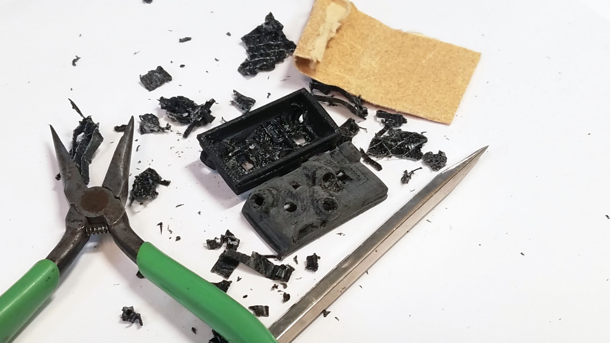
The inside and outside of the printed caps are going to be rough. I use sandpaper, hobby knife and scrapers to make them accurate representations of the original 3D model they need to match.
![]()
I finish the sensor cap with acetone and an ABS/acetone slurry. The truth is that 3D printed objects don't look that great, or at least not to parents, donors and administrators. There are many different techniques that can be used to finish ABS plastic with acetone. I've tried quite a few and this works best for me. Above you can see granulated black ABS plastic (the same plastic used to print the caps) about to be mixed with acetone.
![]()
Here you can see the ABS/acetone slurry, a mostly finished cap and some brushes I was using.
![]()
Here are the finished caps. I did a whole bunch at once.
![]()
The inside of the caps have been cleaned up to match the original 3D model.
![]()
The MLX90615 sensors are fragile so I have recessed them inside the enclosure with a protective bezel protruding out and around their field of view. I use a Dremel grinding tool and sandpaper to clean up the bezels.
![]()
Finished sensor cap plastic ready to have sensors mounted.
5: Testing Components![]()
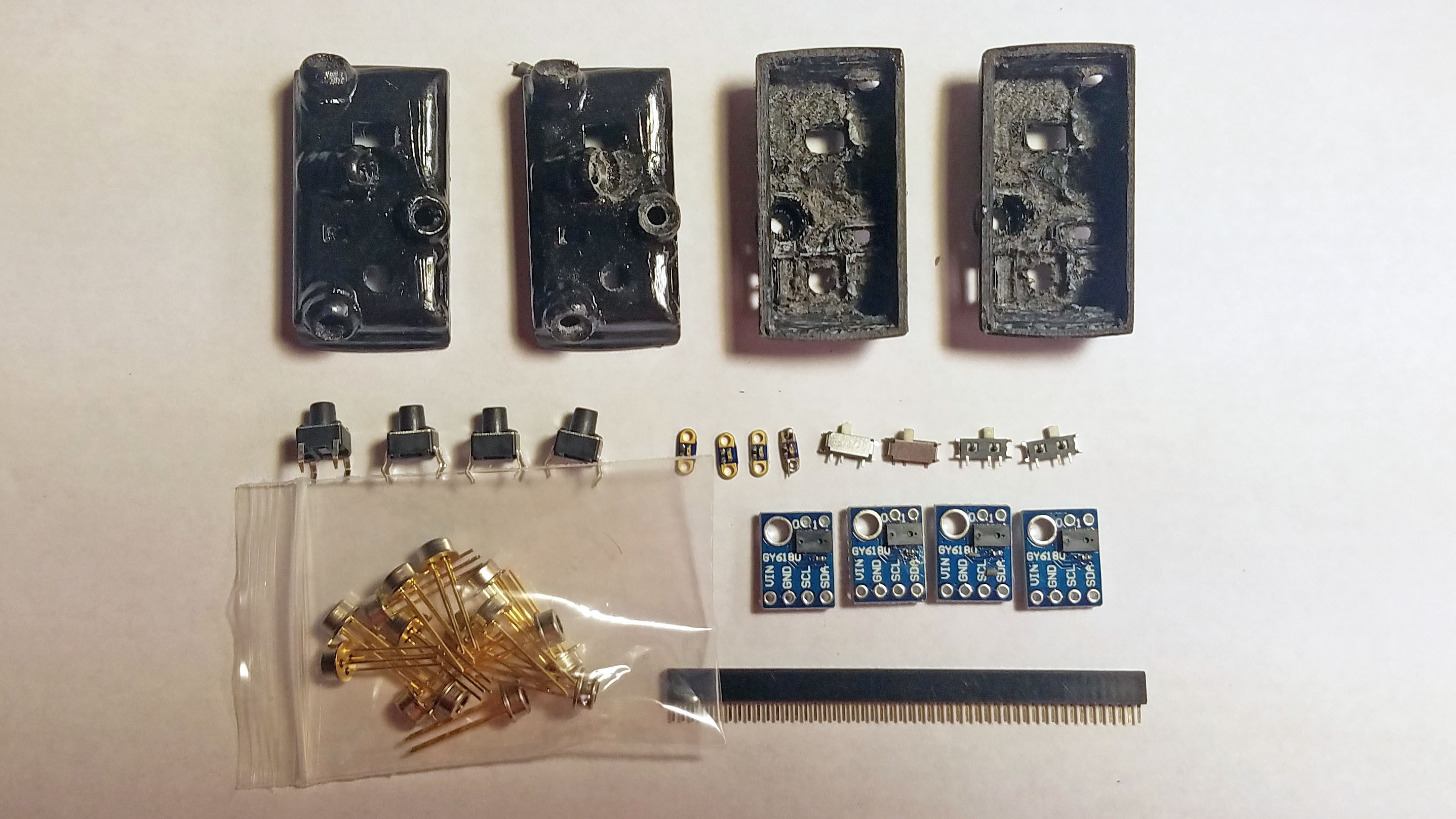
There are many stages at which testing is necessary. Testing saves a huge amount of time in the long run. Above you can see all the components layed out for testing and inspection.
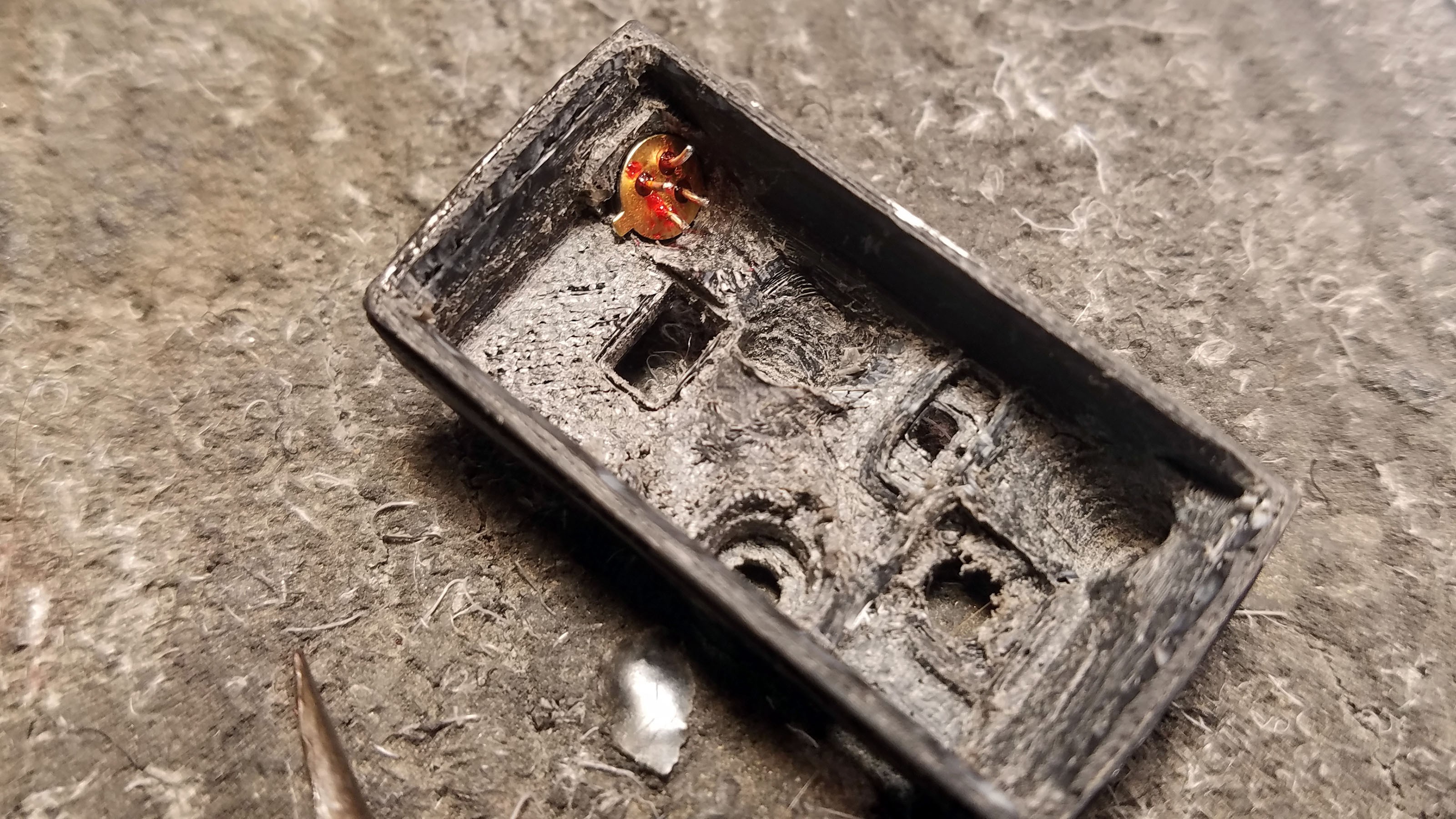
6: Grinding Out Metal Enclosure Bottom![]()
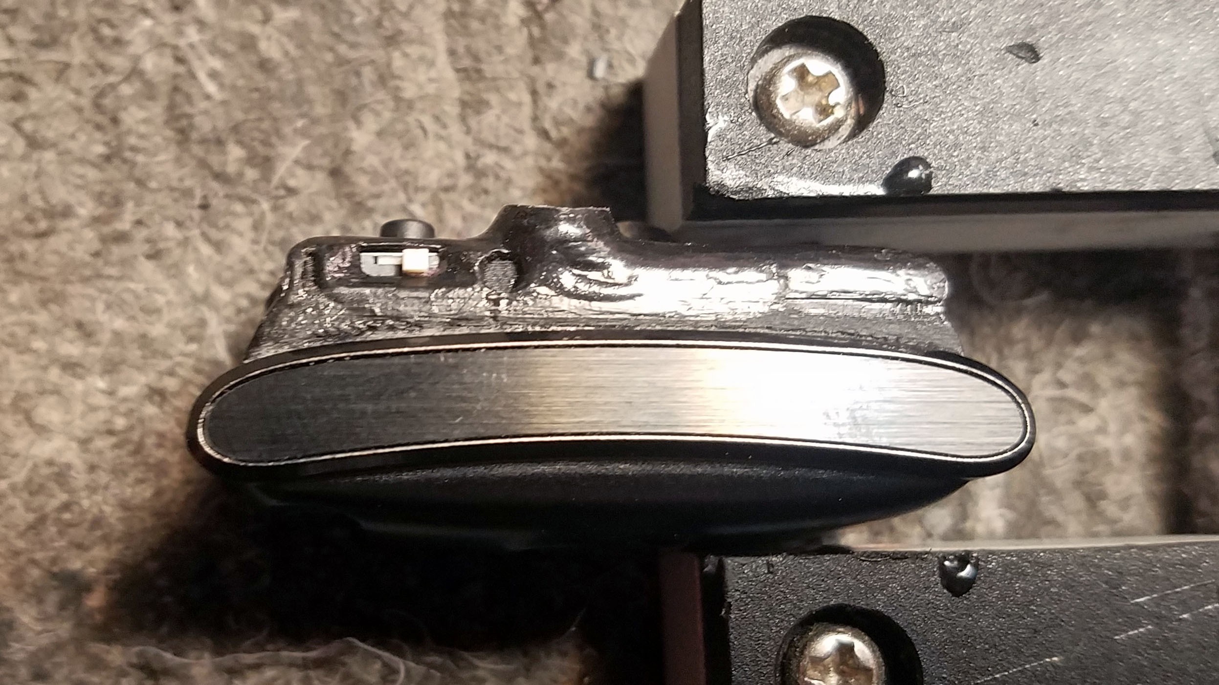
The Tingle needs to interface with an external programmer on a regular basis. The Tingle's Nordic nRF52832 SoC is programmed over a two wire (clock and data) SWD interface. In addition, ground and power from the nRF52 must be exposed to the programmer. An additional GPIO (P3) is exposed for use for debugging (data logging) over serial UART. All five connections are made avalable using a 1mm pitch header pin socket recessed inside the enclosure. To make extra room (and keep the connector flush with the PCB) I grind and outlet into the cast metal alloy enclosure bottom. Here you can see the connector flush against the enclosure.
![]()
![]()
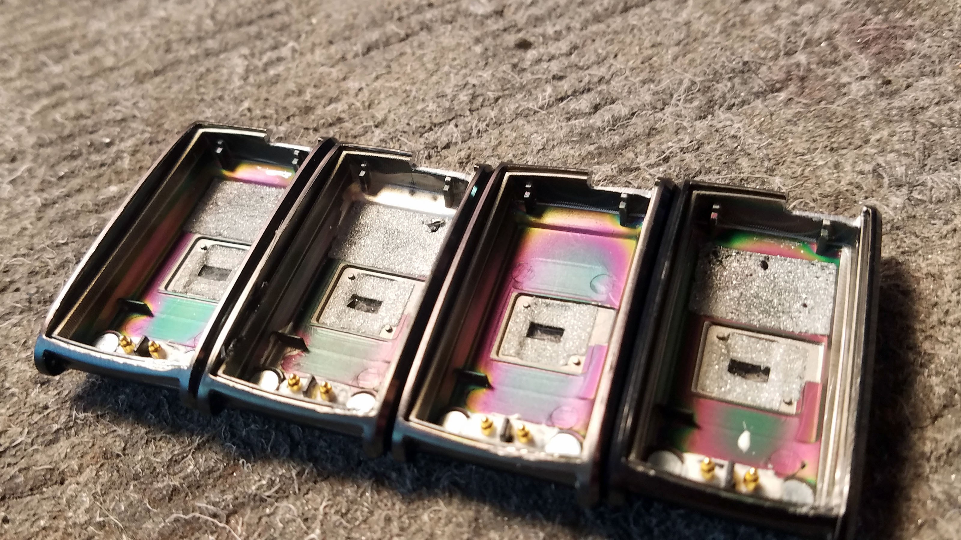
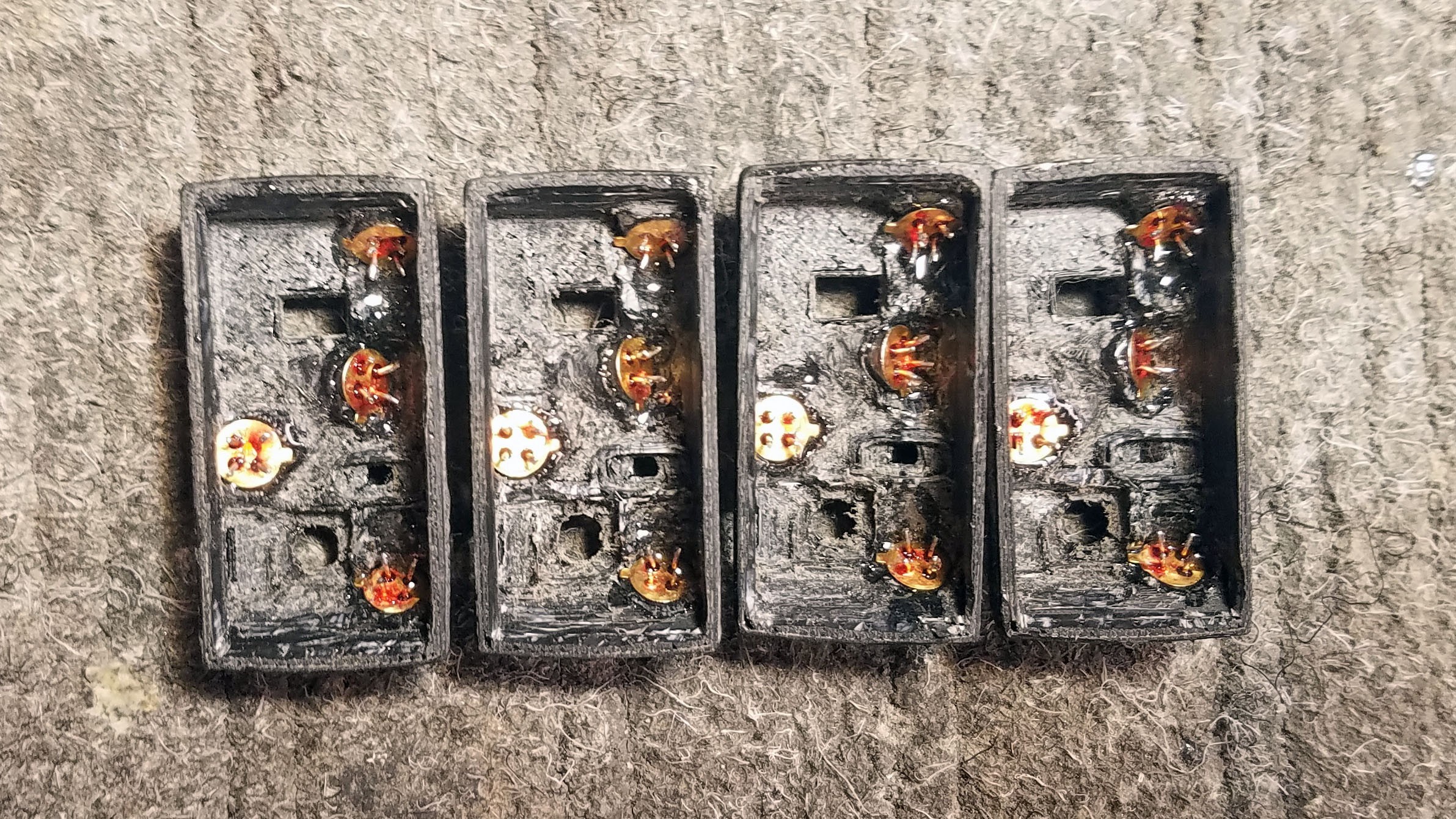
This is what the enclosure looks like after using a Dremel cut-off wheel to grind out room for the connector.
7: Prepping the VL6180 distance sensor
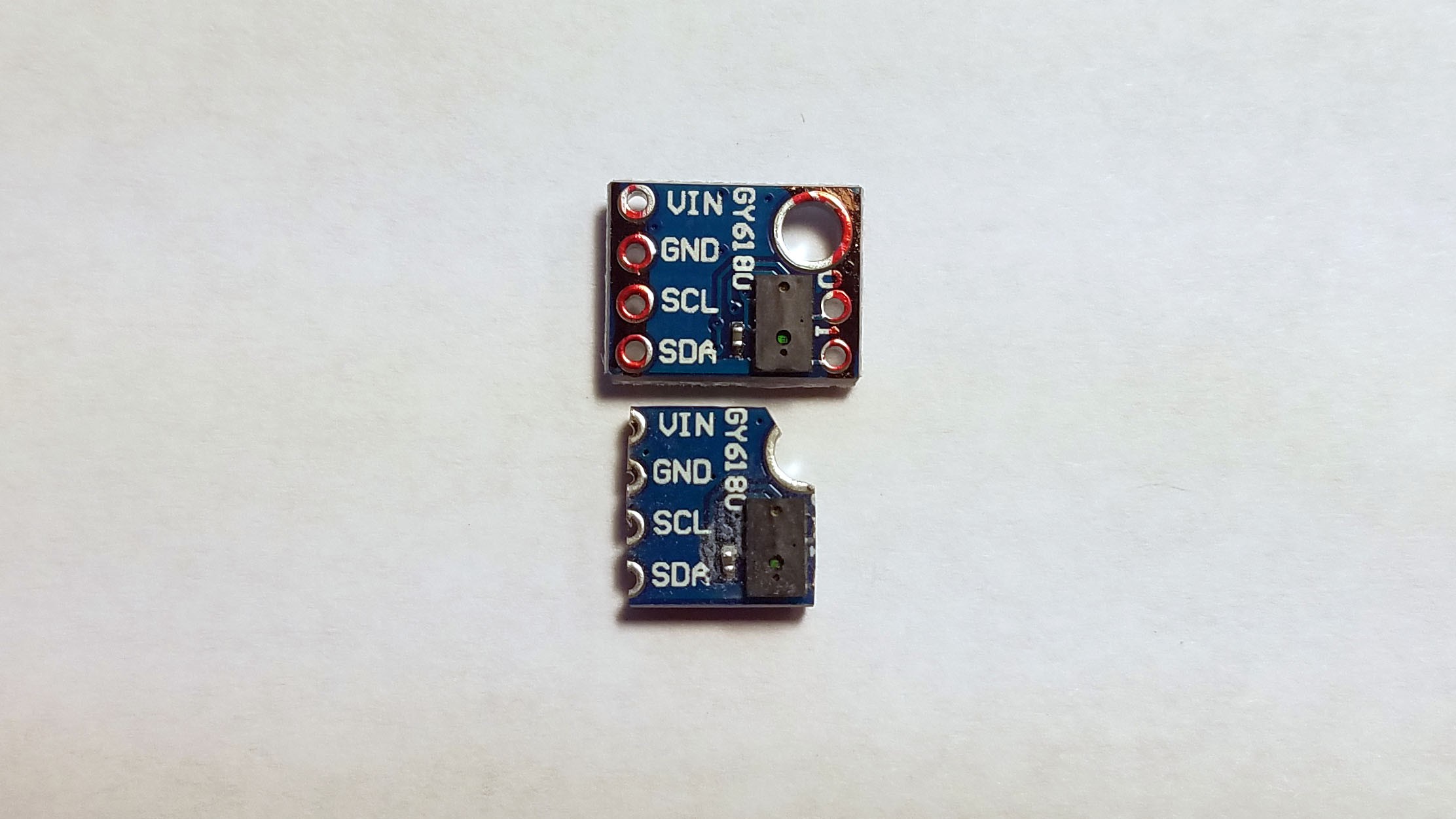
![]()
Above top is a small VL6180 time-of-flight (Lidar) sensor breakout as it looks when first purchased. I use this sensor on an I2C bus along with all the thermal sensors. The two pull up resistors on this breakout cover the I2C needs of the thermal sensors since they are all on the same I2C bus. Above bottom is the same model breakout with all extraneous material ground off with a Dremel cut-off wheel to save space inside the Tingle sensor cap.
![]()
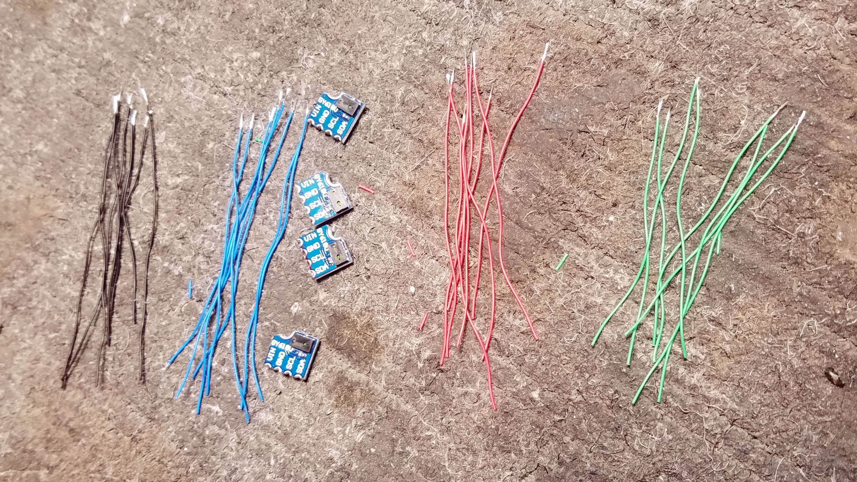
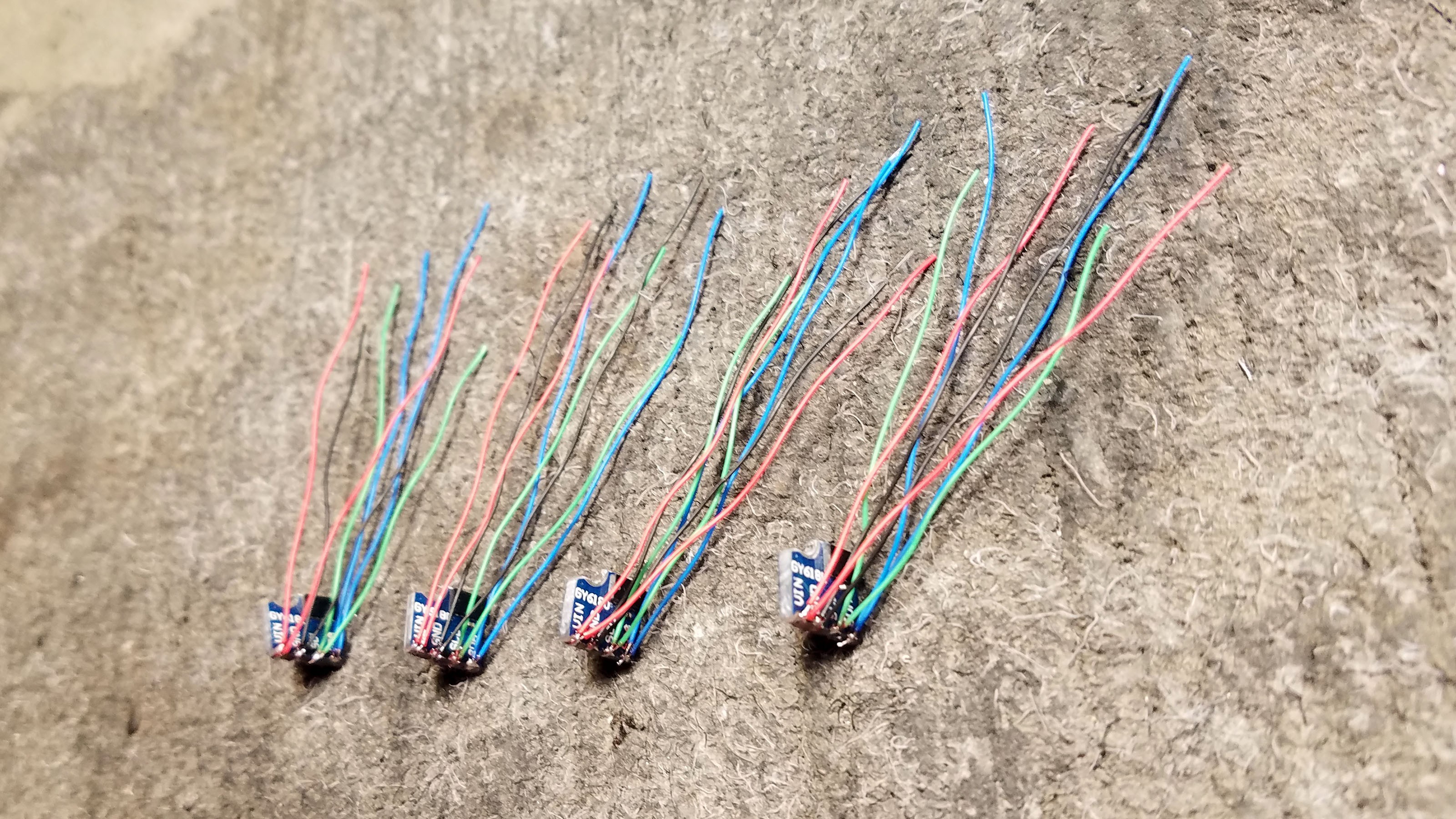
All four sensor breakouts with wires which I will solder to them. The wire tips have been fluxed and pre-soldered.
![]()
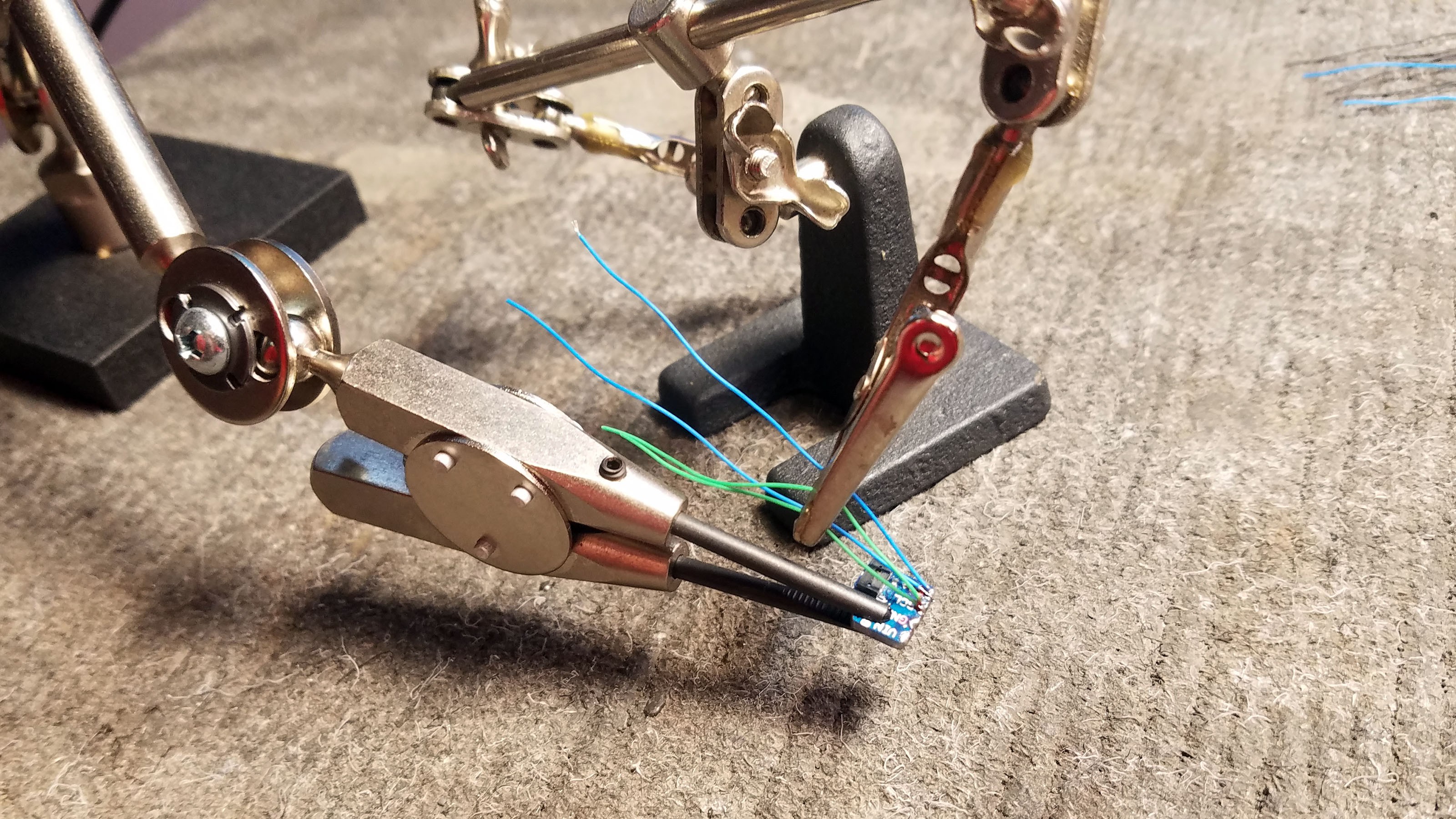
Two wires are soldered each to GND, V+, SDA and SCL. One set of wires will be connected to the N68 PCB and the other set of wires will be connected to the MLX90615 thermal sensors.
![]()
fully prepped VL6180 sensor breakouts.
8: Adding an Antenna
![]()
A little foil antenna was glued to the glass cap of the N68 fitness tracker. Since we removed it, we should replace it. I say "should" instead of "must" because the PCB tracings act as an antenna no matter what. Adding an antenna as I show will increase Bluetooth range though. The white blob on the bottom left corner of the PCB above is a contact for the antenna.
![]()
I solder a 3cm SOLID copper wire to the antenna contact. It is very important that this wire be solid metal if it is to act as an antenna.
![]()
Antenna wires have been soldered onto all four N68 PCBs.
9: Battery Connector Wires for Switch
![]()
Being able to cut off power to prototypes is essential because it is an easy way to reboot them. The easiest way to do this is a switch between the battery and the device. I desolder the ground (black) wire from the battery to the PCB.
![]()
An extension wire is soldered to the battery ground (black) wire for eventual connection to a switch.
![]()
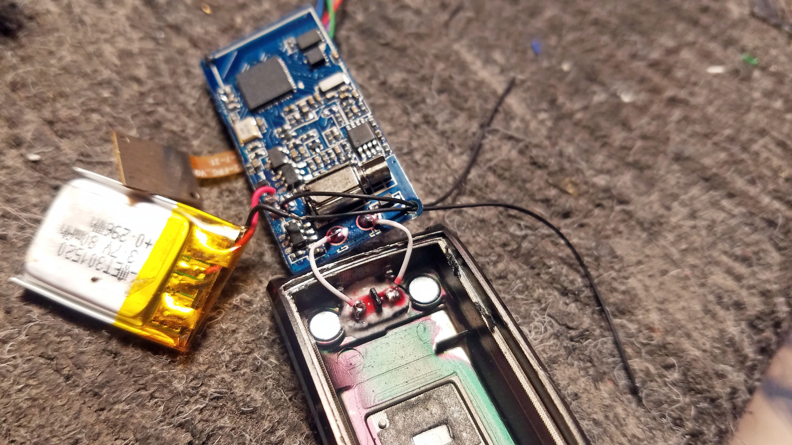
Another wire is soldered to the PCB where the battery was previously connected.
![]()
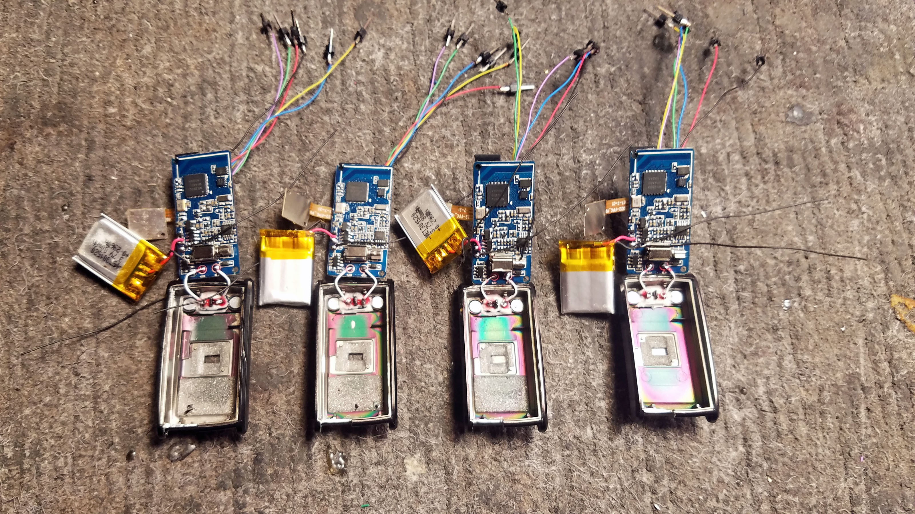
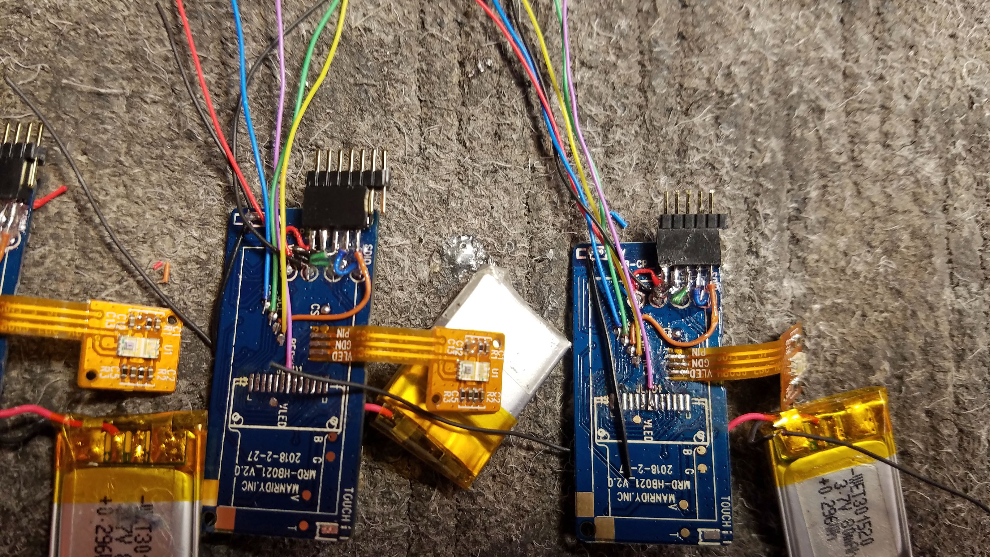
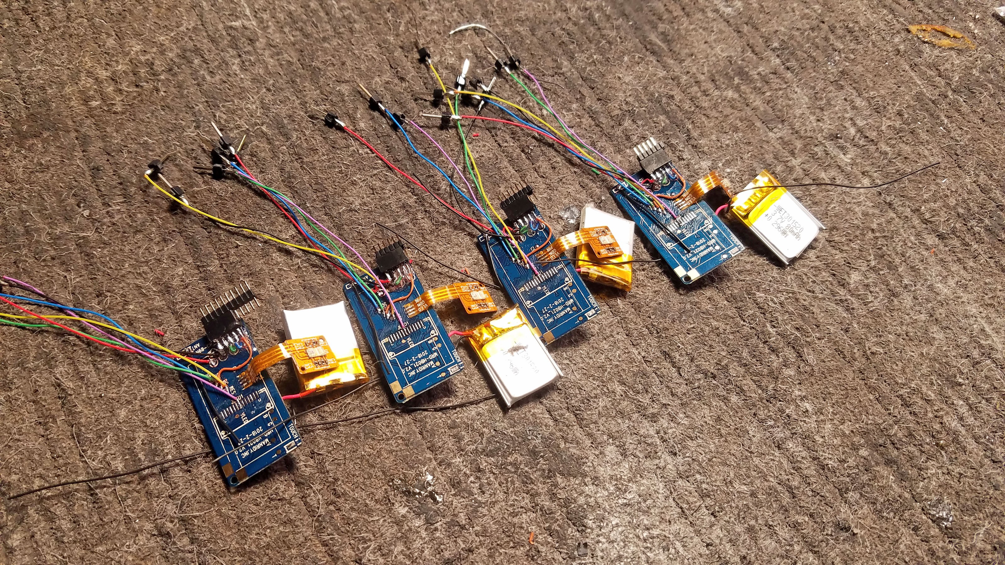
Here you can see battery connection extension wires on all four N68 PCBs
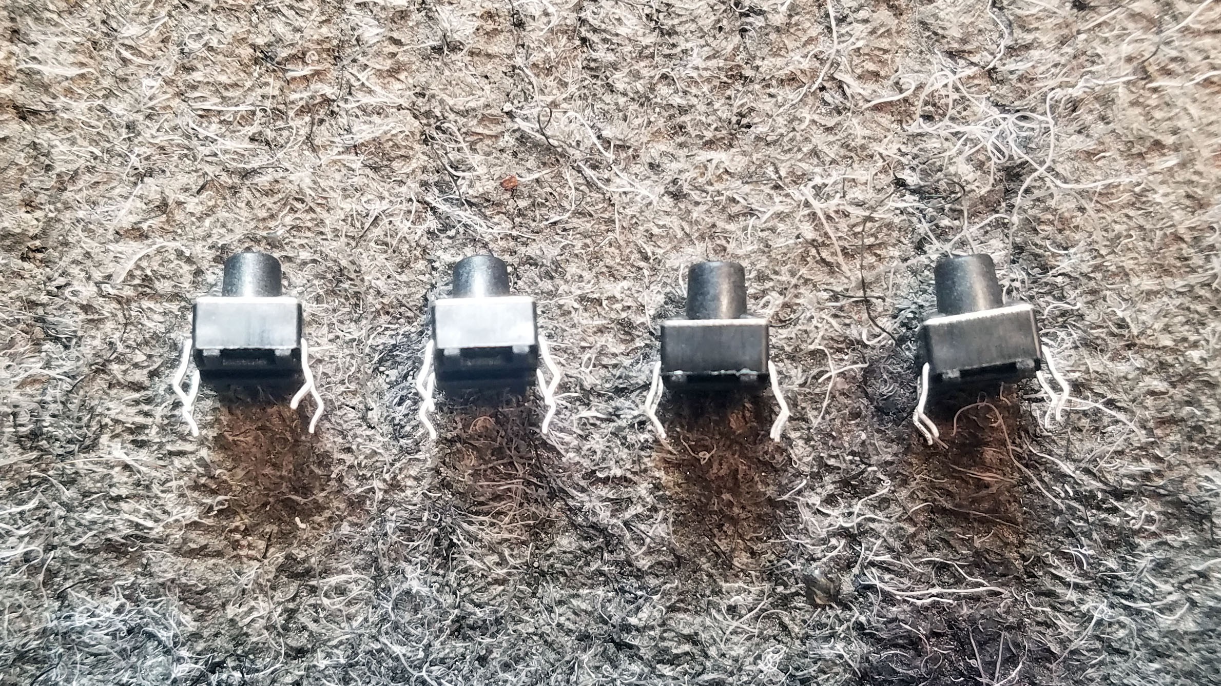
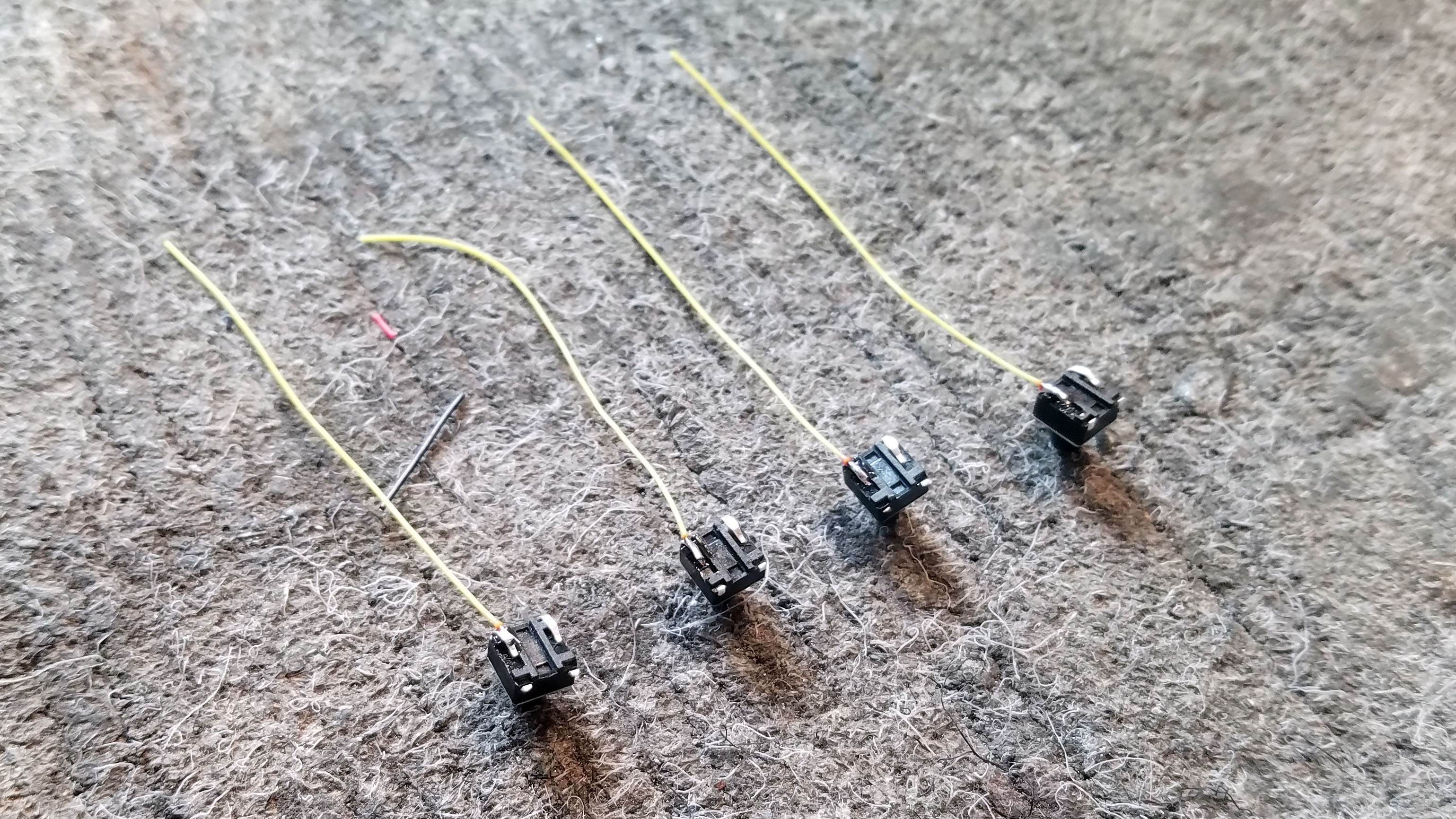
10: Prepping the Tingle Sensor Cap Buttons![]()
Your typical momentary push buttons.
![]()
I cut off extra pins and press the two remaining against the body of the button.
![]()
I solder one wire to each button. This one yellow wire will be connected to the matching yellow wire soldered to the N68 PCB.
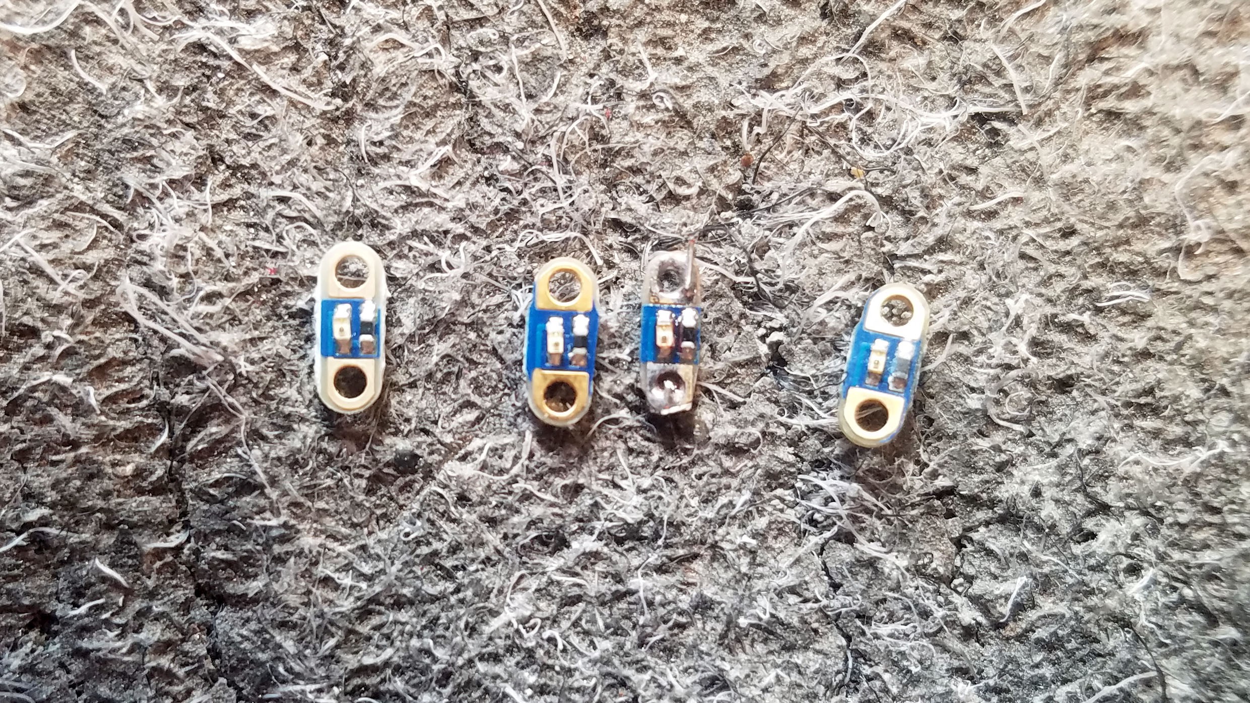
11: Prepping the LED breakouts
![]()
These little SMD LED breakouts from Tiny Circuits are handy. I could have accomplished the same effect many ways but this is convenient and durable.
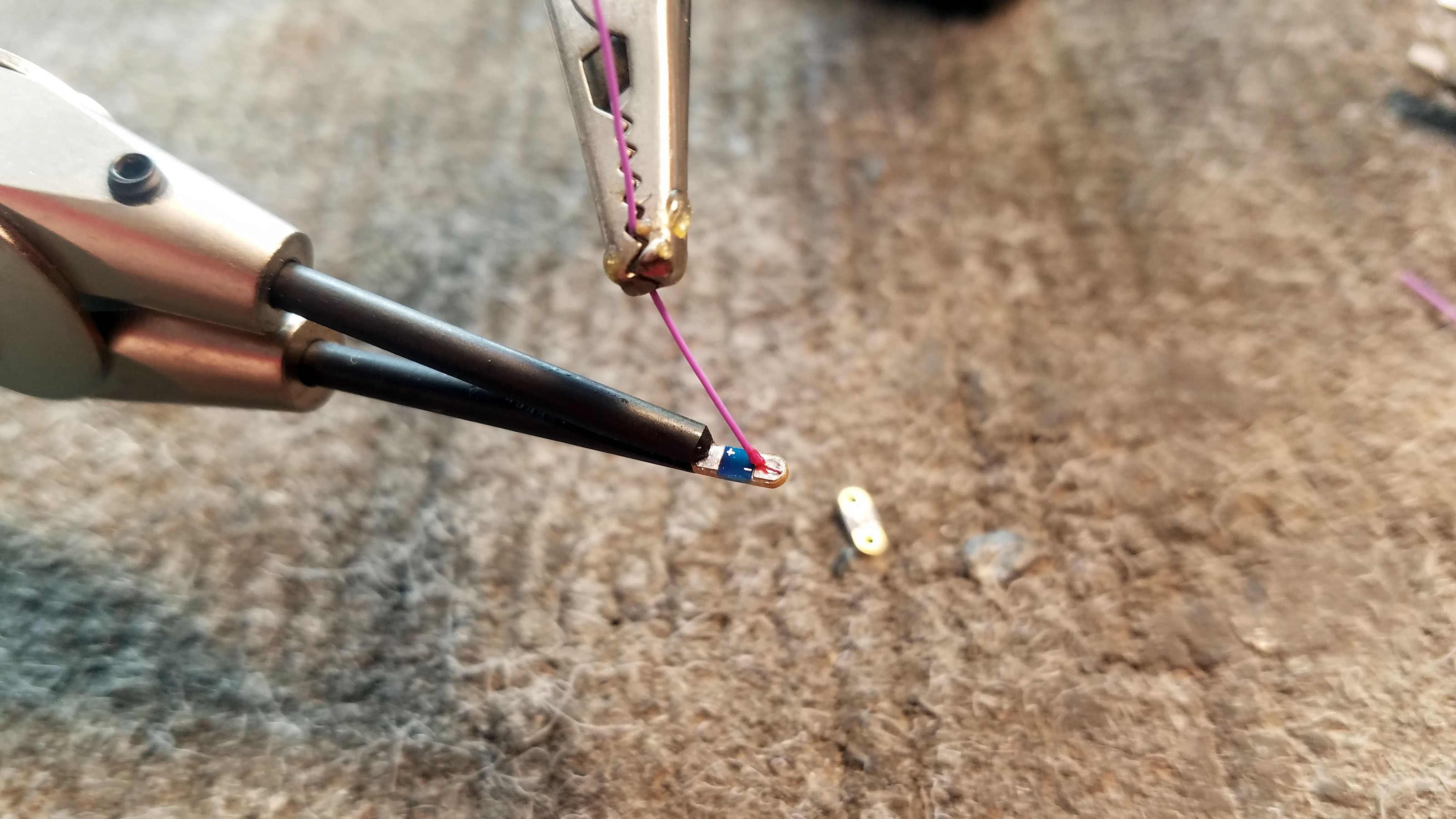
![]()
I solder one wire to the negative connector on the breakout. This purple wire will be connected to the matching purple wire on the PCB.
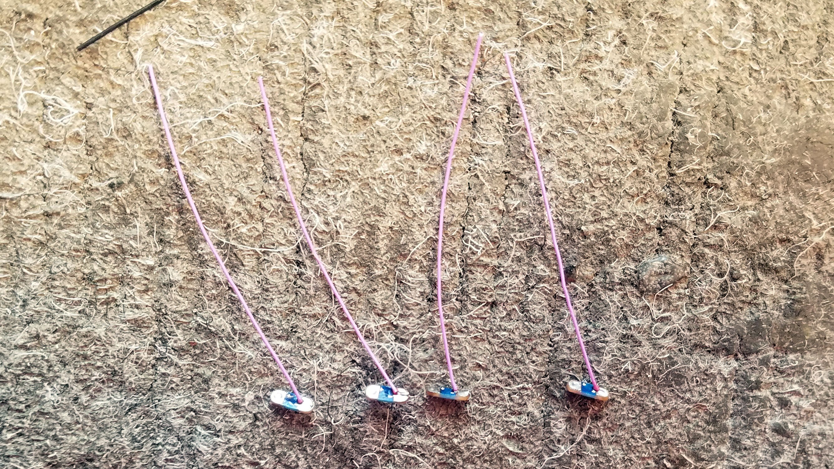
![]()
Here you can see all four LED breakouts with wires attached.
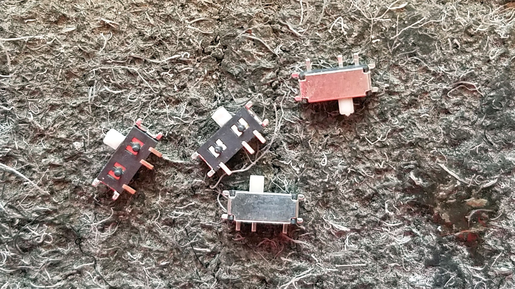
12: Prepping the SMD Switch
![]()
These switches are really small. They are connected to the N68 battery.
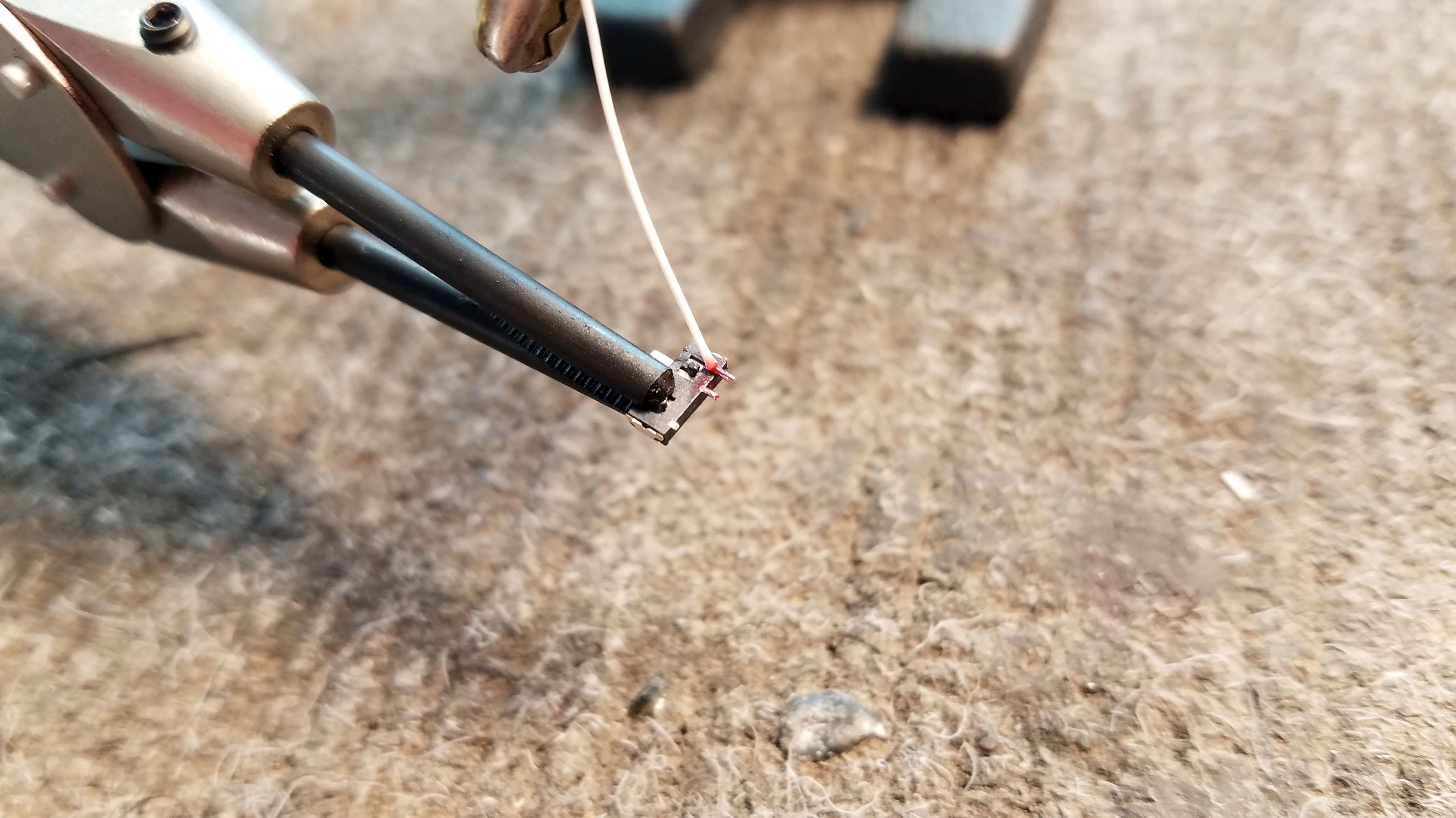
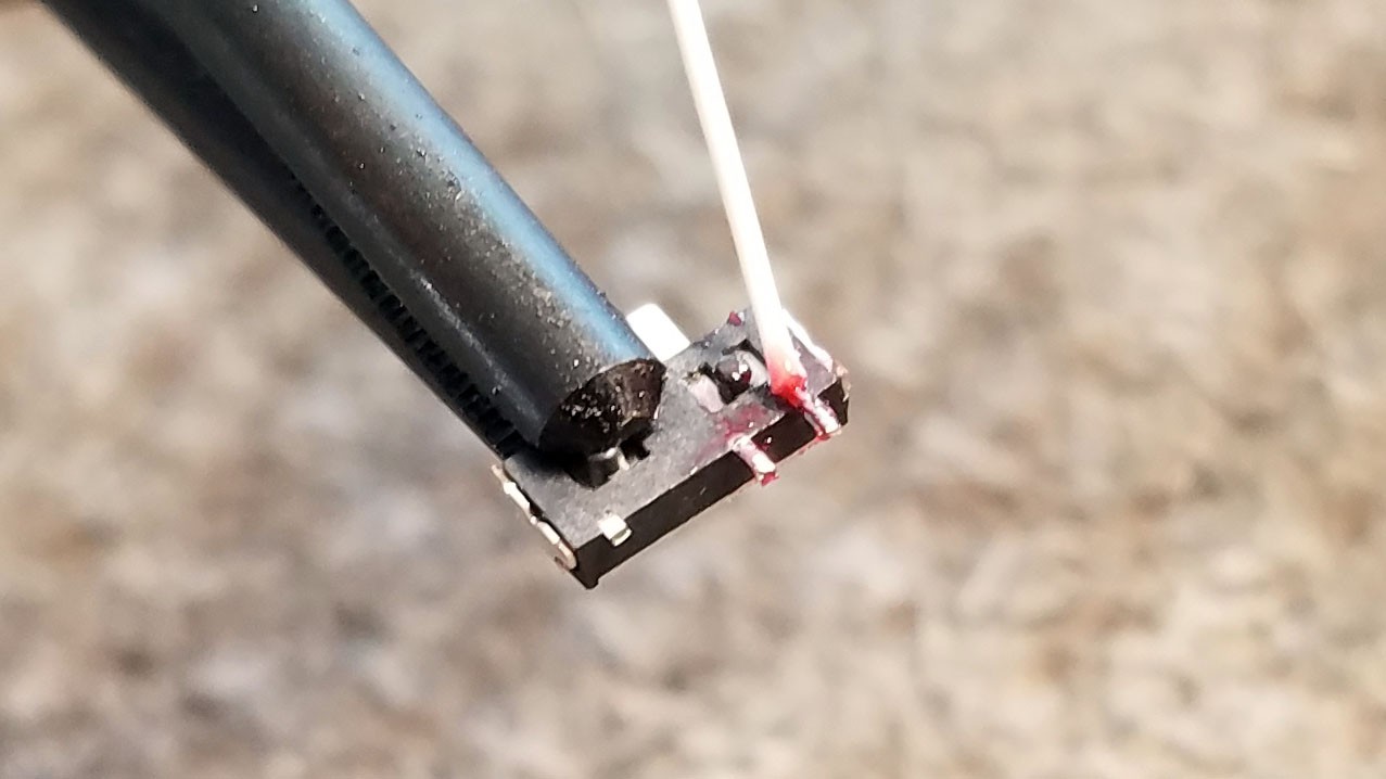
![]()
![]()
Wires are soldered to each of the two pins. These wires will be connected to the black wires previously soldered to the battery and battery/PCB connection point.
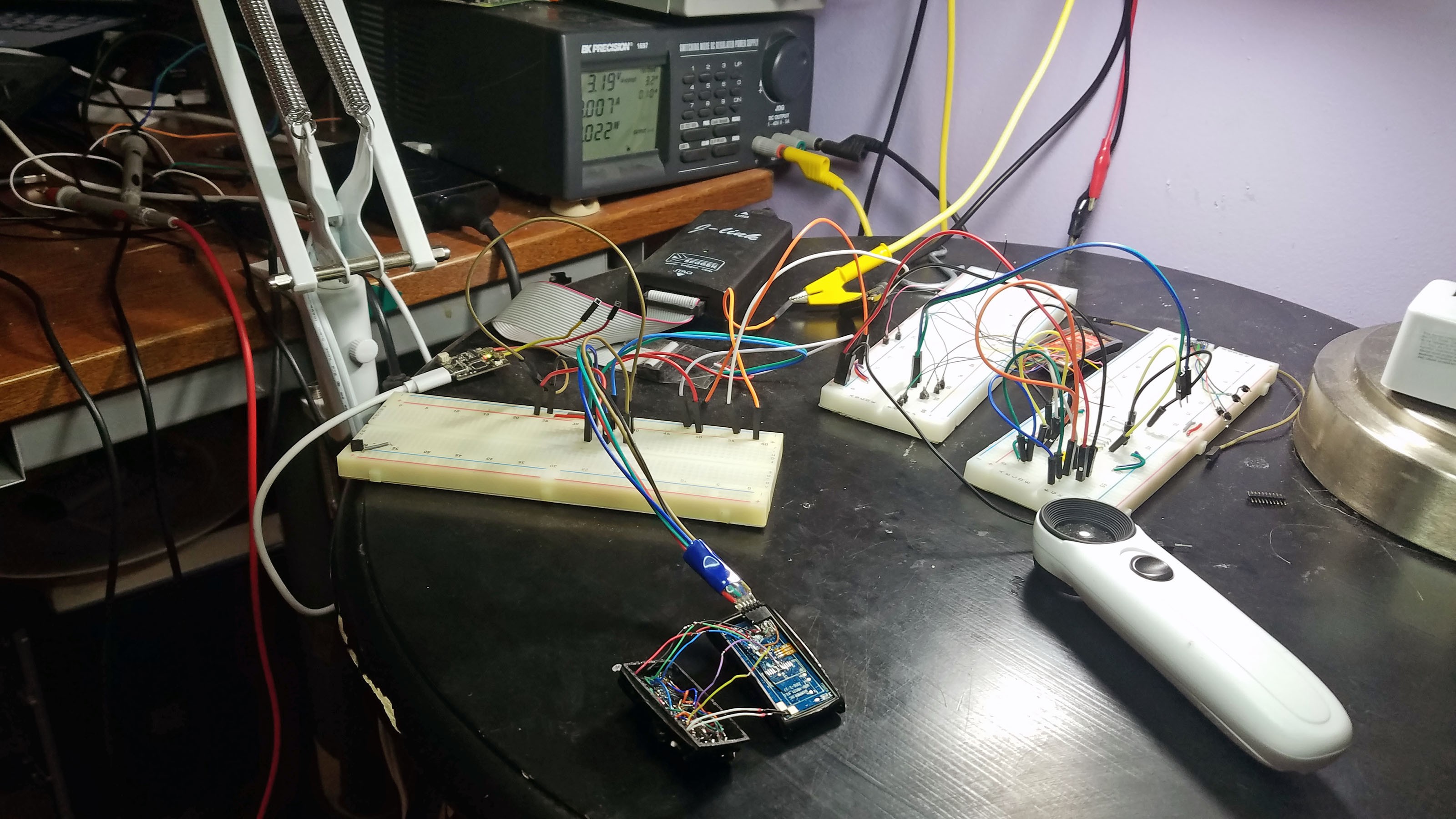
13: Testing the N68 PCB before Attaching Header Pin Socket Connector
![]()
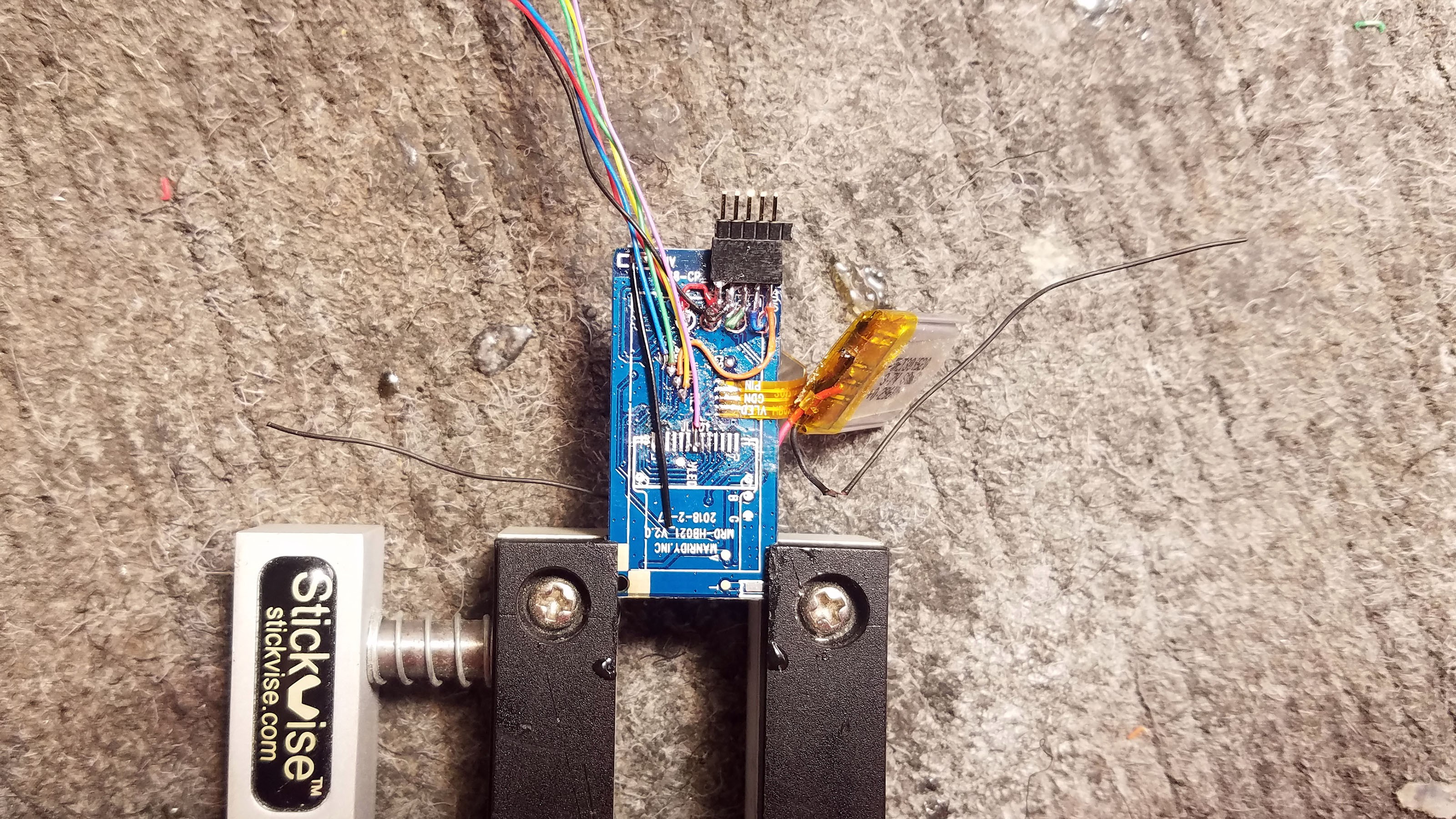
If you are building prototypes for yourself and they stop working, no big deal. If you hand off a prototype to a colleague, or even worse a tester/patient, and it stops working, it really sucks. Hand building prototypes the way that I am demonstrating is an inherently unstable process. There are many many ways in which things can go wrong and chances are that one of them will. Obsessively testing throughout the build process is the only way to ensure that this process produces a durable prototype. I constantly inspect everything that I do under a jewelers loupe. I wiggle each wire to make sure the solder connection is good. I drop everything from a height of two feet every now and then for a little stress testing. I also breadboard all the components multiple times throughout the build process. Here I am connecting the SWD programmer to the N68 PCB to make sure everything is working the way it should.
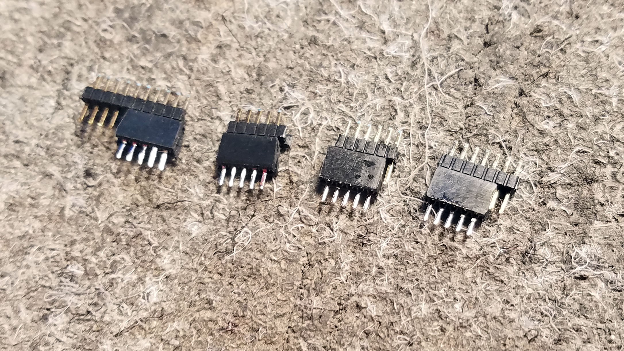
14: Adding a Header Pin Socket Connector
![]()
All the wires we are soldering to the connector at trimmed back.
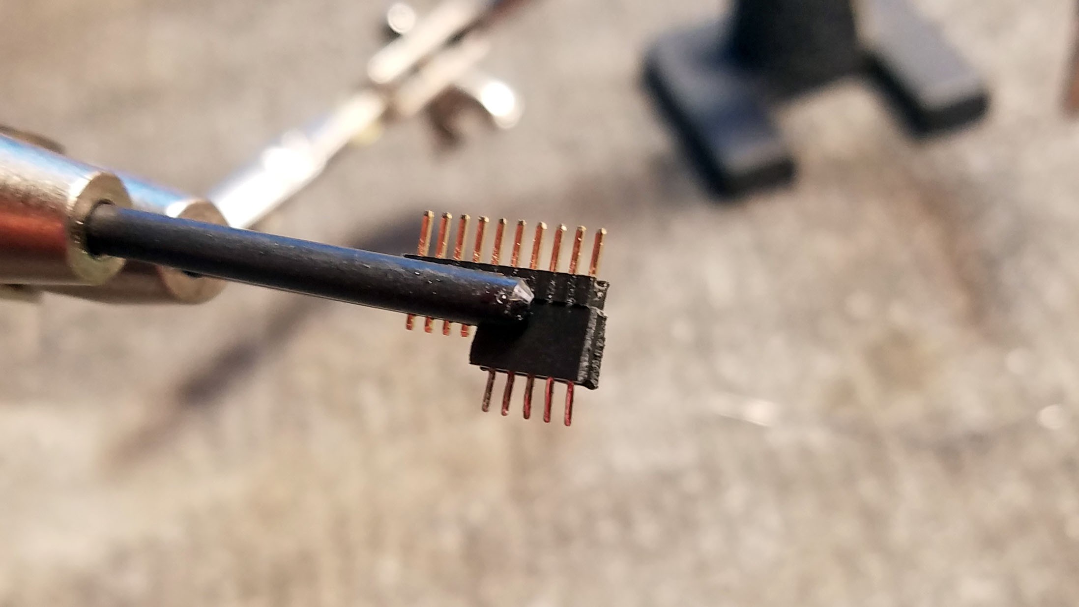
![]()
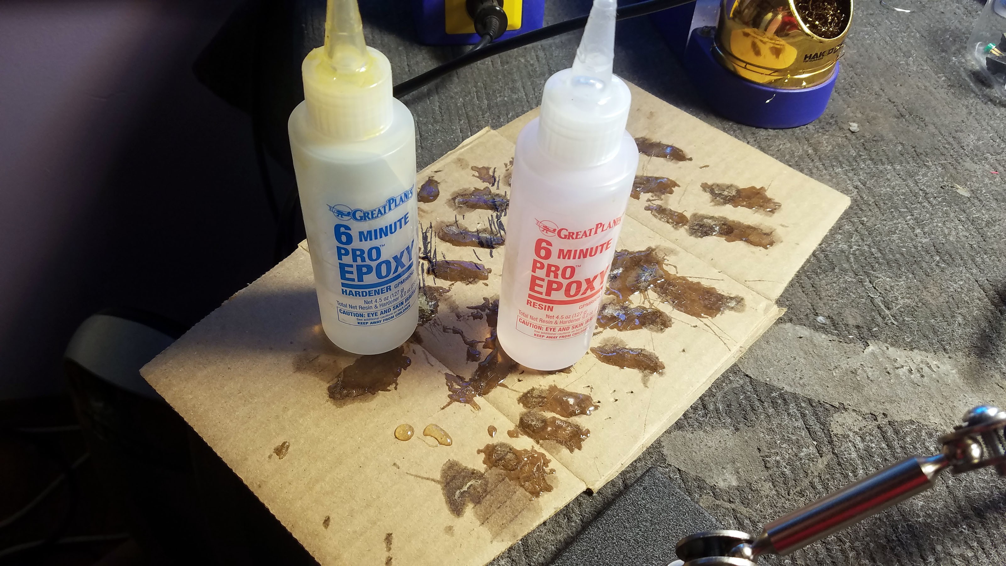
I put header pins in the socket to keep out epoxy and make sure the heat from the soldering iron doesn't warp the inside of the socket.
![]()
As always, all solder connection points are fluxed and pre-soldered.
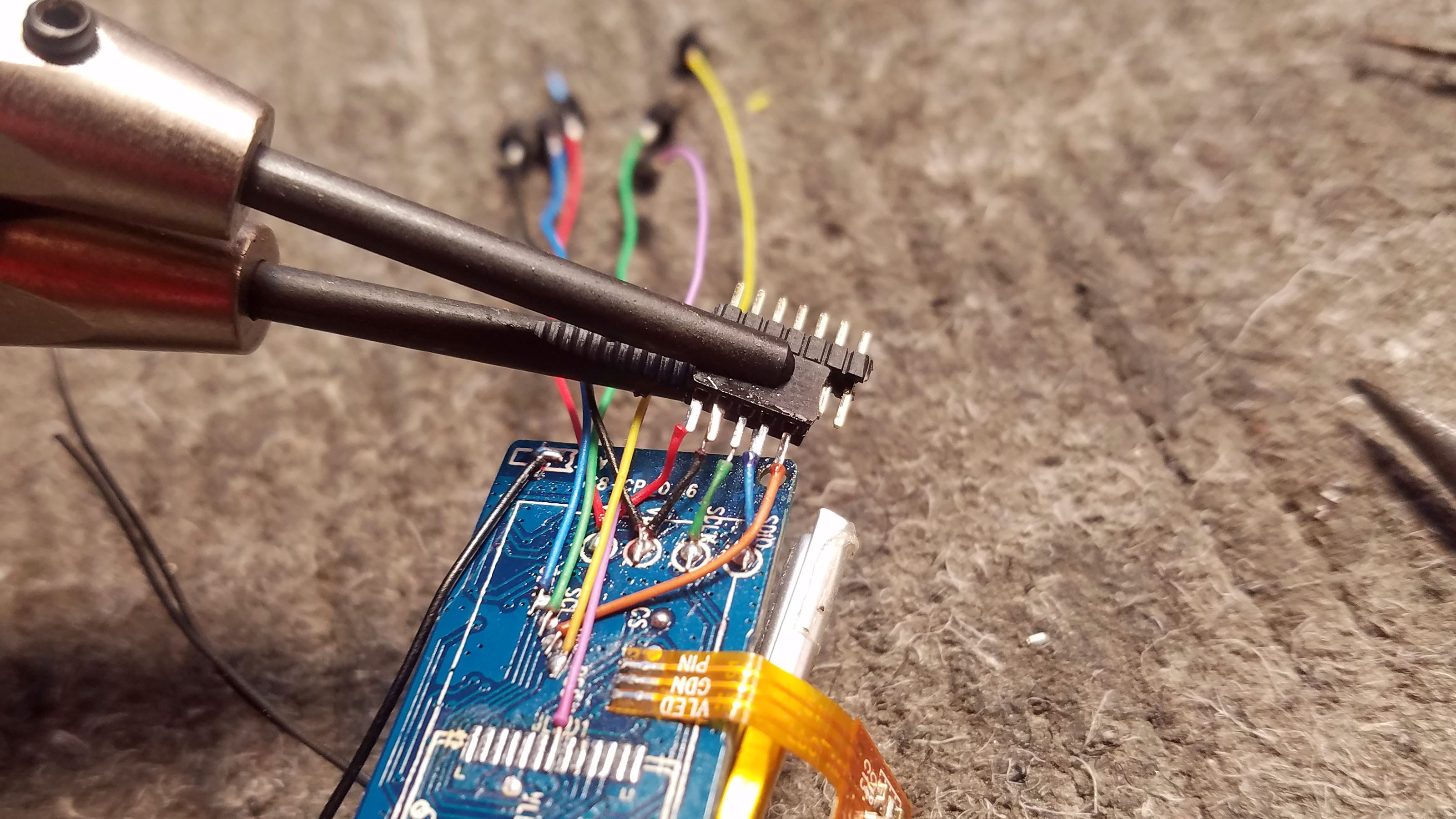
![]()
Soldering the socket to the PCB wires.
![]()
I start on the outside with my brown Serial TX wire.
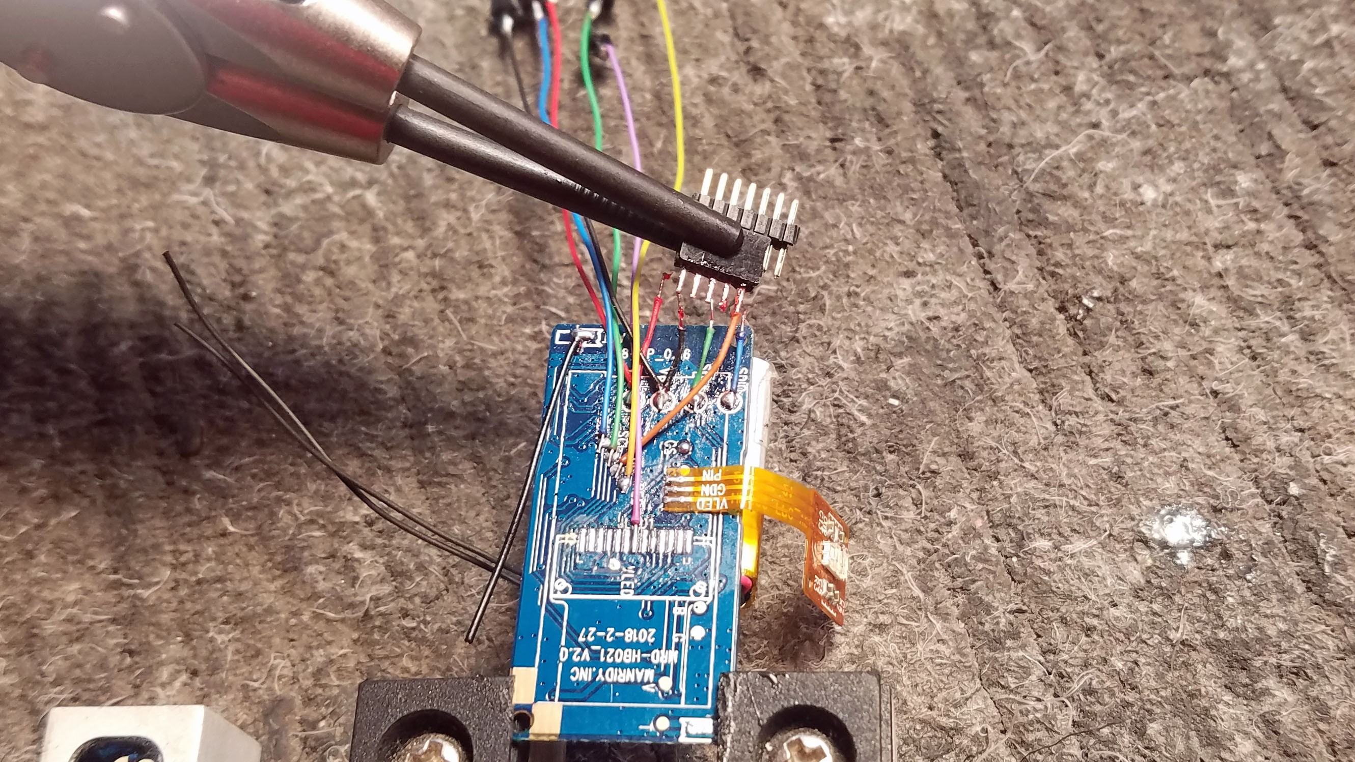
![]()
All five wires soldered to the header pin socket
![]()
The header pin socket connector is epoxied to the PCB to stabilize it.
![]()
The connector has been soldered to the PCB. It should extend 1.5mm over the edge of the PCB.
![]()
A little perspective...
![]()
For this step multiple examples are nice. You have to fold the wires against the PCB to get everything fitting nicely.
![]()
All four PCBs with connector sockets attached.
15: Prepping the MLX90615 Thermal Sensors
![]()
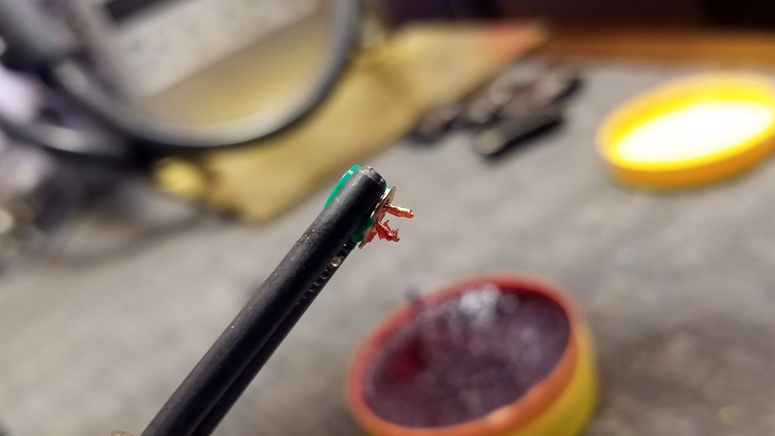
Each thermal sensor has to be individually programmed before use. I cover this in the "Programming the Tingle" project log. Here the leads of the sensor have been trimmed and bent back. Leaving 2mm works well for me.
![]()
I just dunk the sensor leads in flux.
![]()
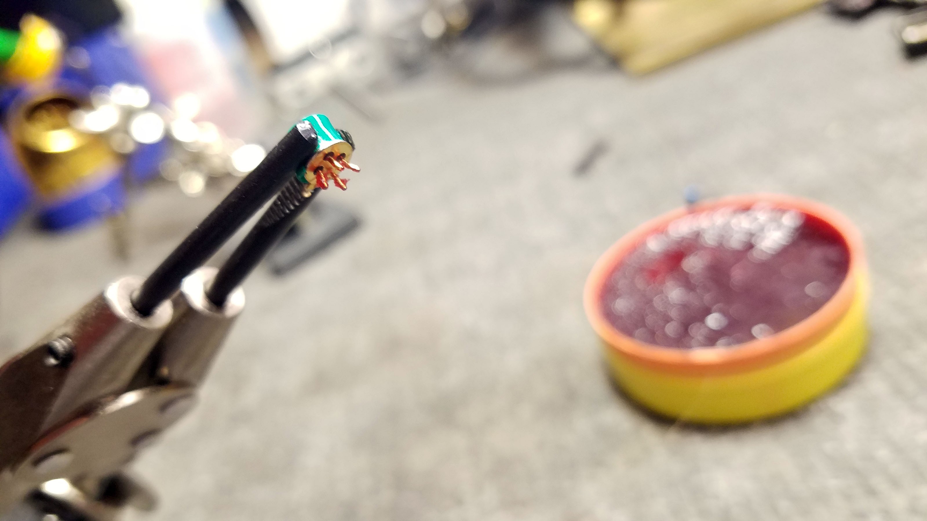
You have to be careful when soldering the leads. The body of the sensor is connected to ground, and there is only 0.3mm of space between each lead and the body where the lead meets the body. If any solder gets in the dark area you can see at the base of each lead above it will short that connection to ground.
![]()
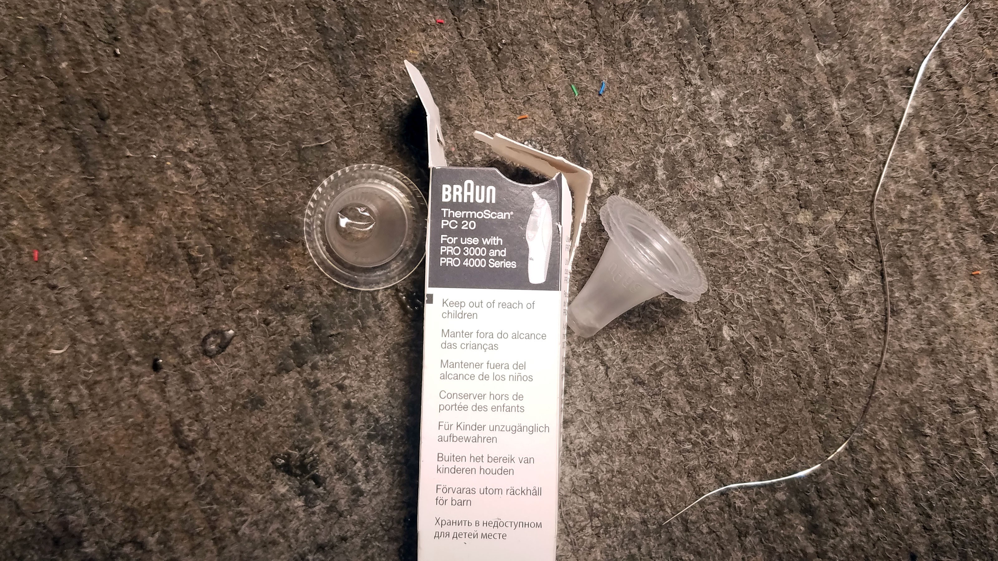
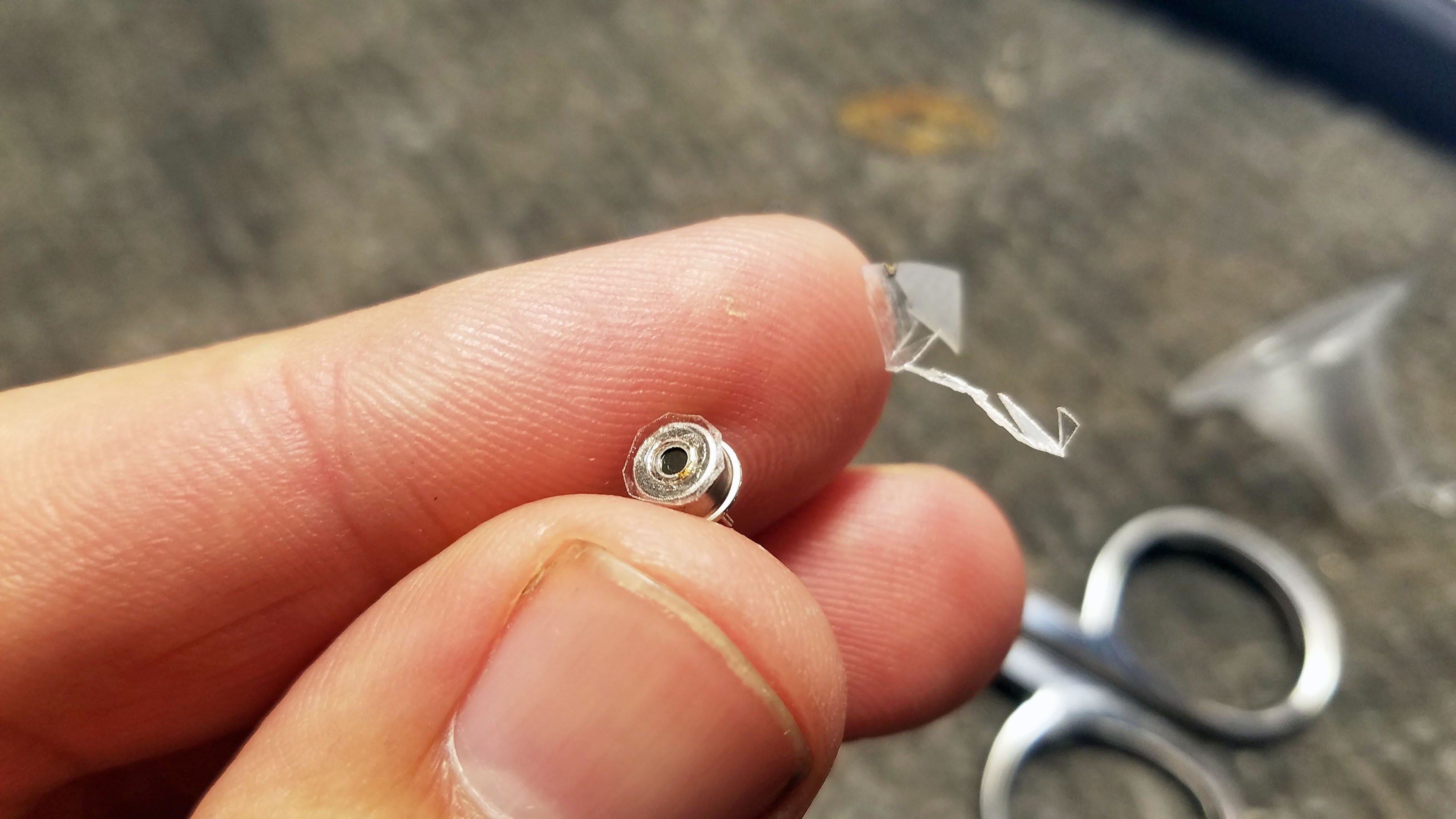
The MLX90615 sensor elements are exposed and very fragile. If you were to smear peanut butter on them by accident, the whole device sensor cap would be toast - they are very difficult to replace. I use an ear thermometer cover to protect them. I hate this part of the build, but it works well and I have yet to find a better way of doing things. The ear thermometer covers are extremely thin but surprisingly strong.
![]()
Double sided tape. Bet your weren't expecting to see that. I use double sided tape to attach a small piece of ear thermometer cover to the top of the thermal sensor.
![]()
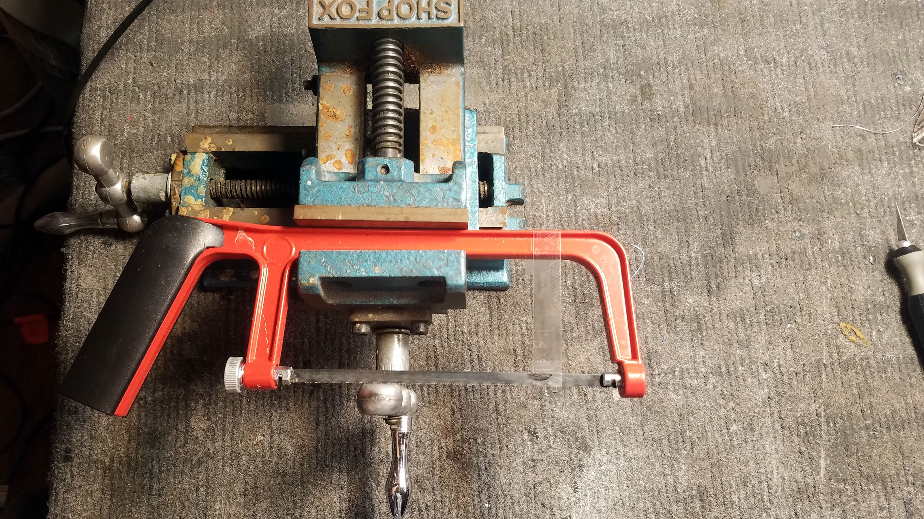
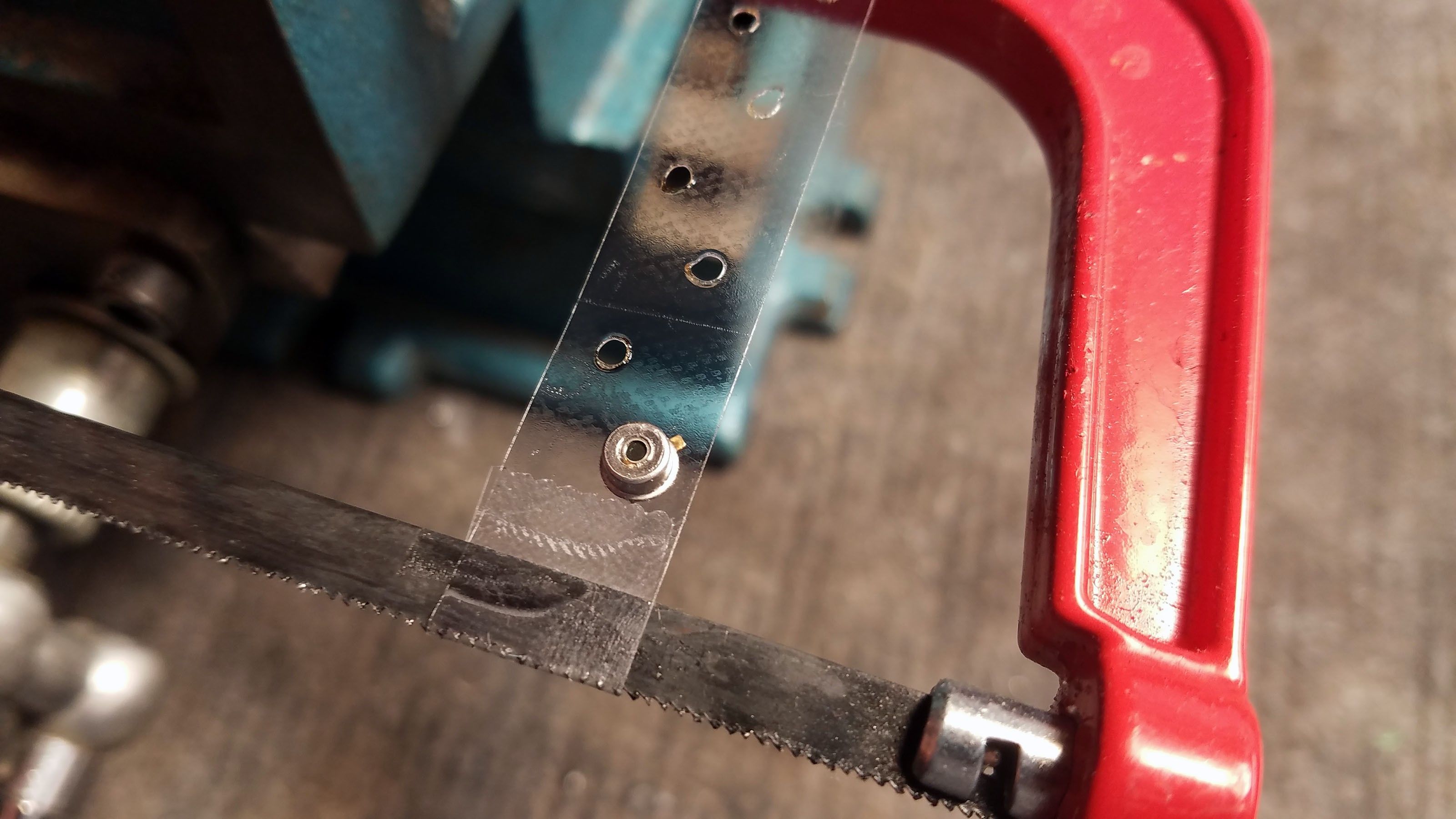
Here is where things get a little wild. The hole in the tap must exactly match the size of the MLX90615 sensor element. Too big and there wont be enough tape left on the sensor to keep it attached. Too small and it will cover up the sensor itself. I spread a peace of tape across a mini hack saw (could have used any number of things) and carefully poke holes in it with a soldering iron. I poke a whole bunch of holes for each sensor because it takes a couple tries to get a hole the right size.
![]()
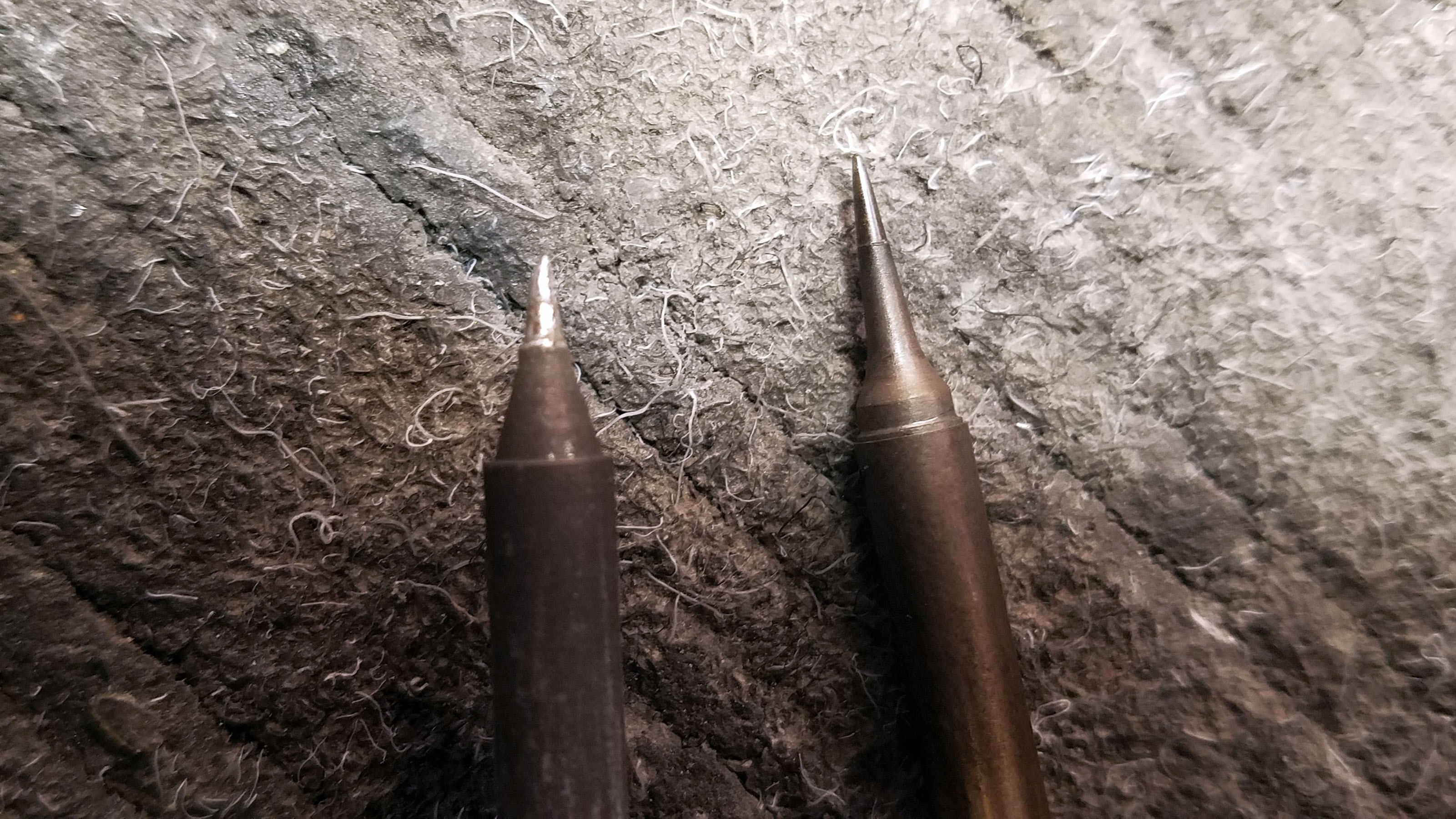
I switch from my primary iron tip (left) to a really long tip I only use for poking holes in plastic.
![]()
Poking holes in double sided tape.
![]()
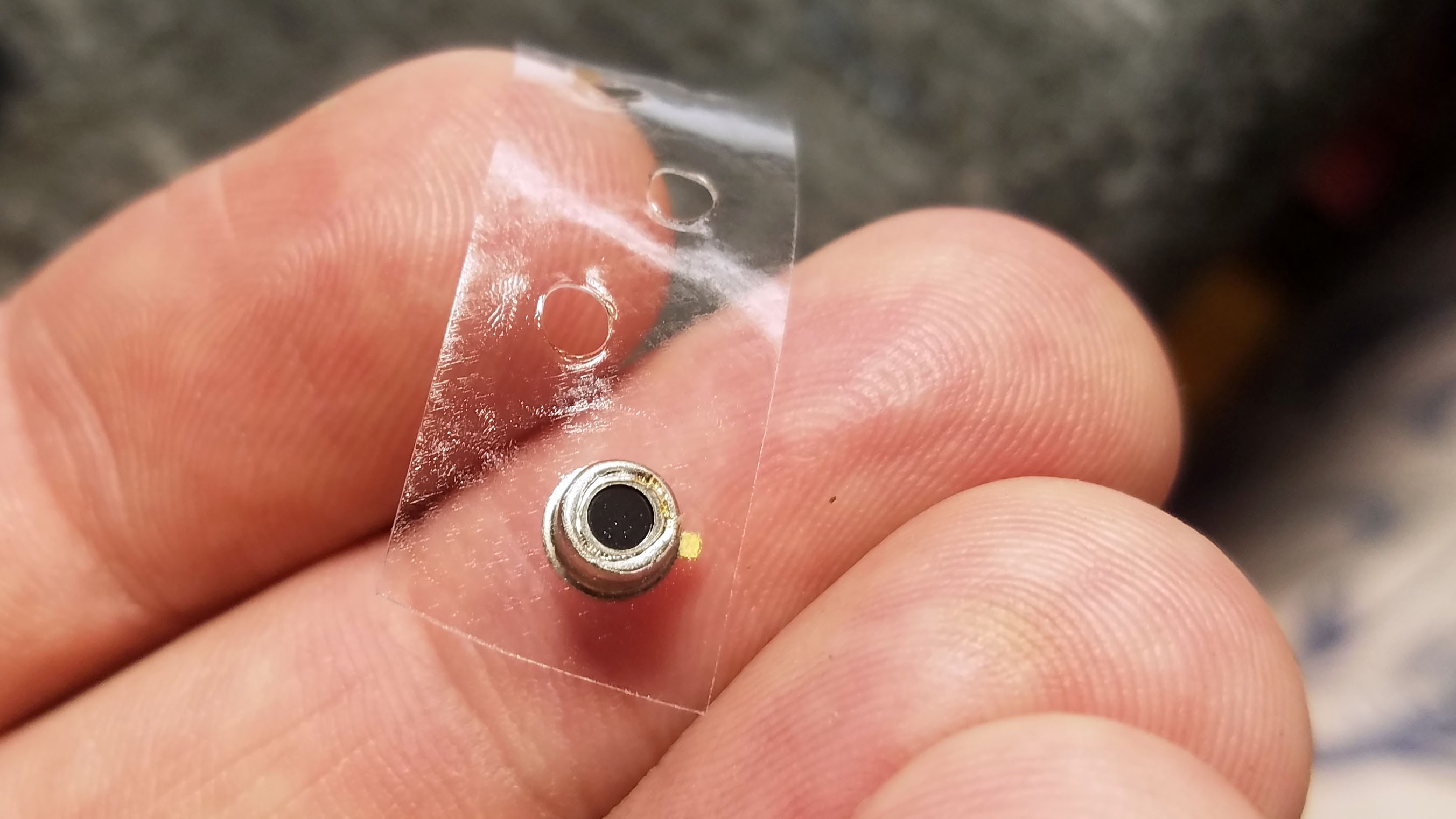
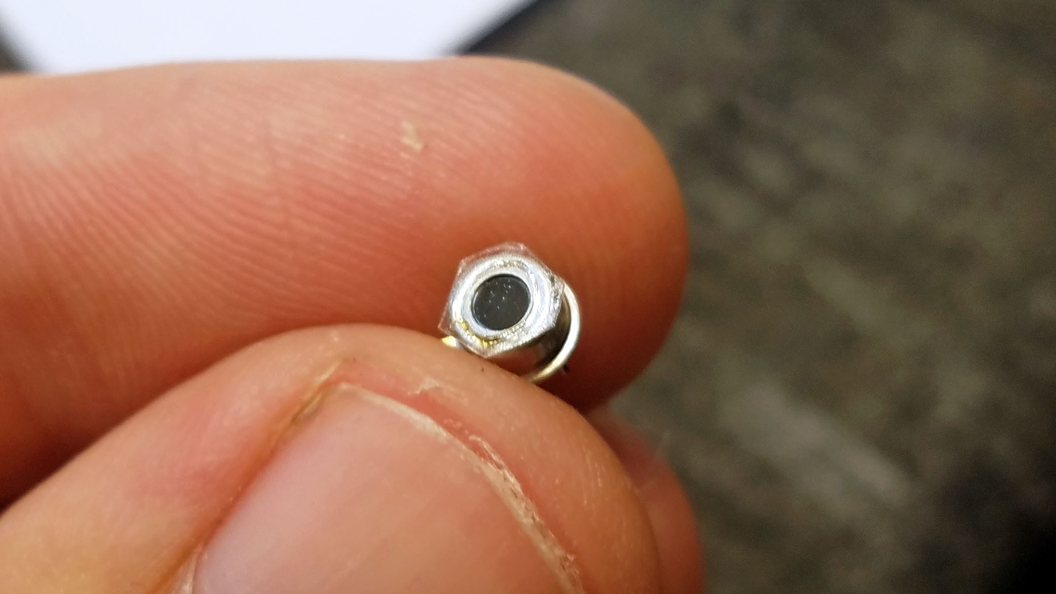
Thermal sensor mounted on hole that is just the right size.
![]()
There are two different versions of the MLX90615 thermal sensor: one with a large sensing element and one with a small sensing element. I'm still trying to figure out which is best so I alternate at the moment. The small ones are definitely easier when it comes to this stage of the build.
![]()
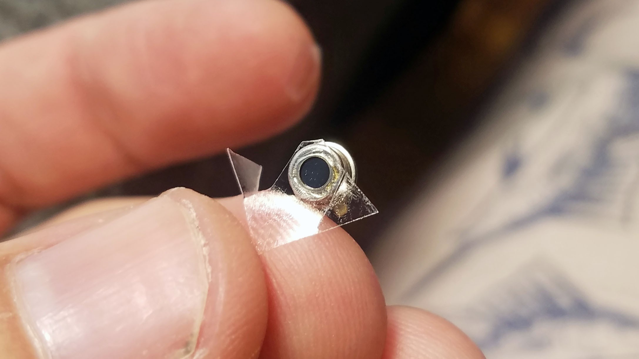
Close up of thermal sensor mounted on tape hole.
![]()
Trimming the tape from the top of the sensor.
![]()
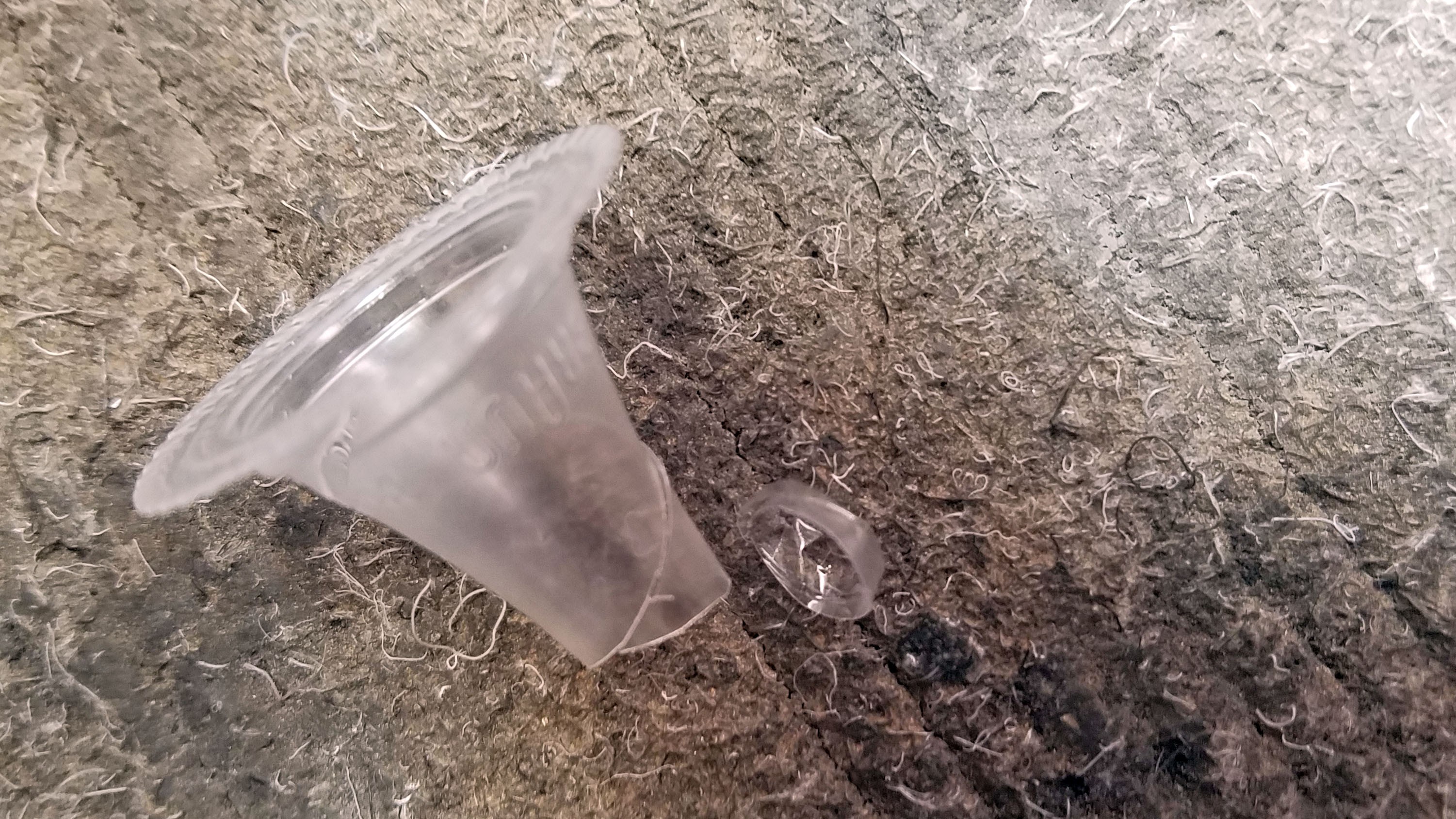
We are left with a tiny, tiny ring of double sided tape.
![]()
Even more tiny on the MLX90615 version with a larger sensing element.
![]()
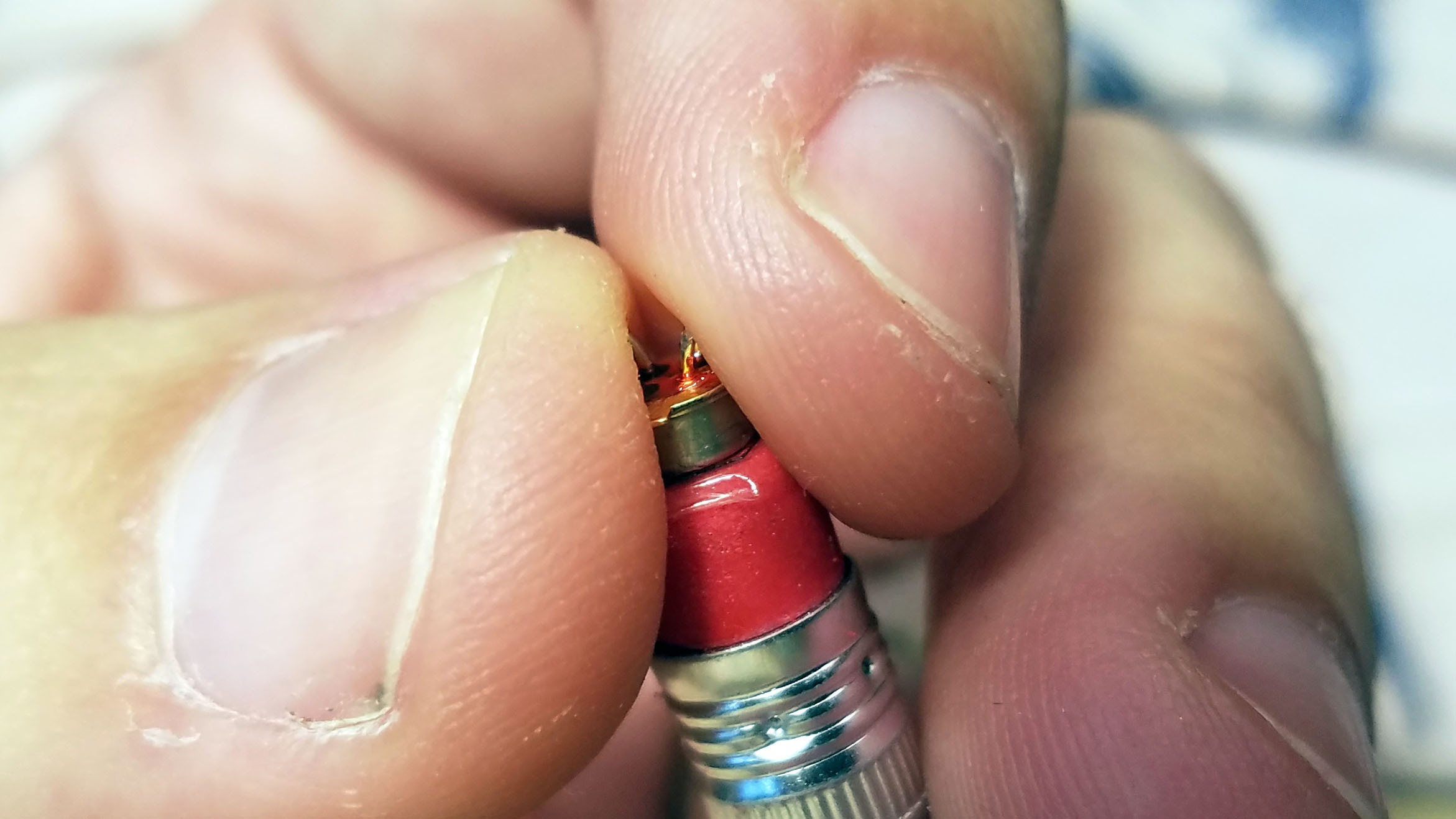
I only use the tip of the ear thermometer cover.
![]()
I wrap the tip of the ear thermometer cover over a pencil eraser to flatten it and make sure there are no folds. Then I press the MLX90615 thermal sensor with double sided tap ring against the ear thermometer cover material.
![]()
Here you can see more clearly.
![]()
The excess ear thermometer cover material must be removed.
![]()
Here is the fully prepped thermal sensor ready for mounting in the 3D printed sensor cap. If any peanut butter gets on it you can clean it with a Q-tip dipped in rubbing alcohol. This also makes the Tingle more water resistant.
16: Mounting the Thermal Sensors
![]()
The thermal sensors are pressed into the designated area of the 3D printed sensor cap. It is extremely important that the right thermal sensor go in the right place. Refer to the diagram in step 4 which shows where each sensor goes. Each thermal sensor has its own unique address programmed into it (see "Programming the Tingle"). Sensor I2C addresses are 2A (sensor 1), 2B (sensor 2), 2C (sensor 3), and 2D (sensor 4).
![]()
All thermal sensors mounted. A small amount of epoxy is used to fit them in place. I epoxy them one at a time to make sure the placement is perfect.
17: Test Components Before Sensor Cap Assembly
![]()
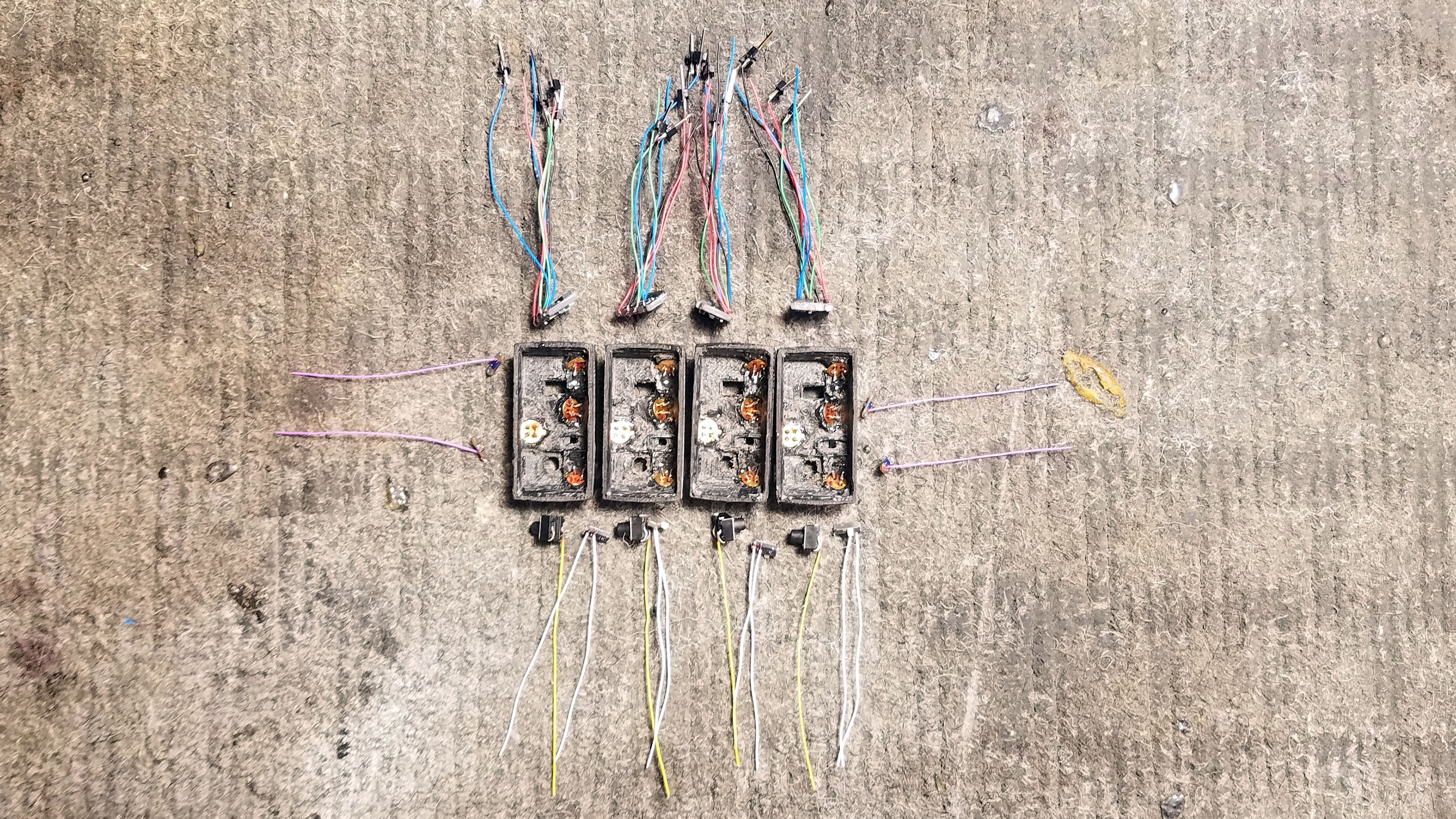
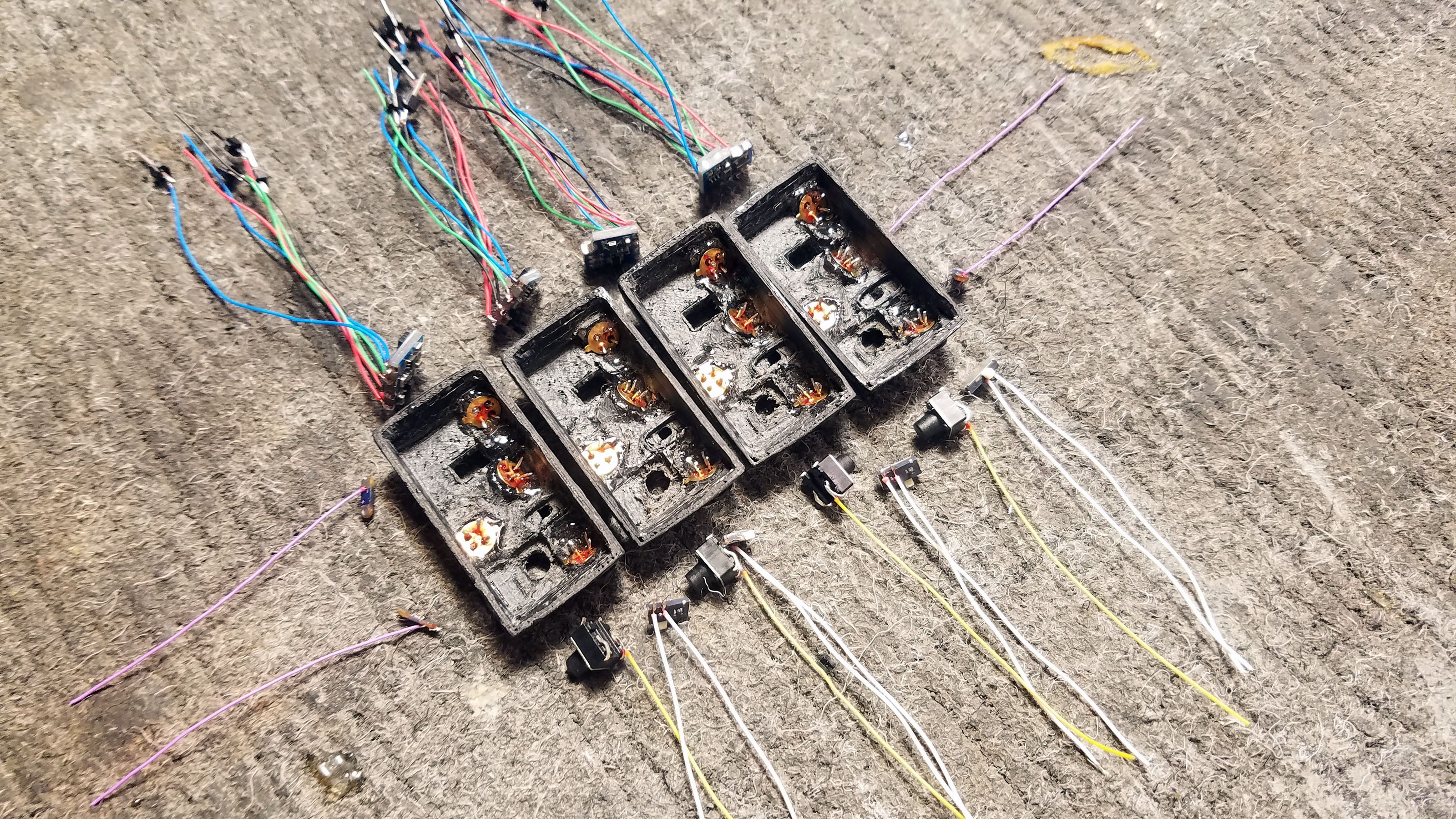
Here you can see all our prepped components.
![]()
Another angle. All components and connections should be inspected and stress tested. Depending on how much testing has been done up until this point in may be prudent to breadboard everything and live test with production firmware.
![]()
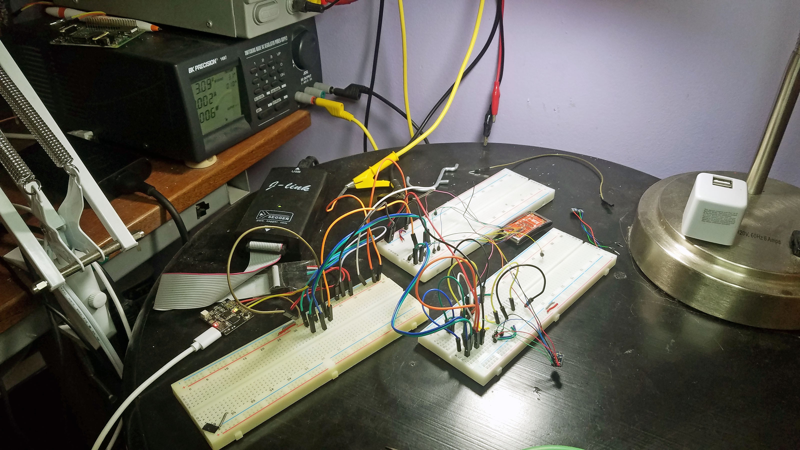
Here I am bread boarding a VL6180 distance sensor to test it. I have an extra N68 fitness tracker wired up to a breadboard just for testing components.
18: Mounting the VL6180 in the Sensor Cap
![]()
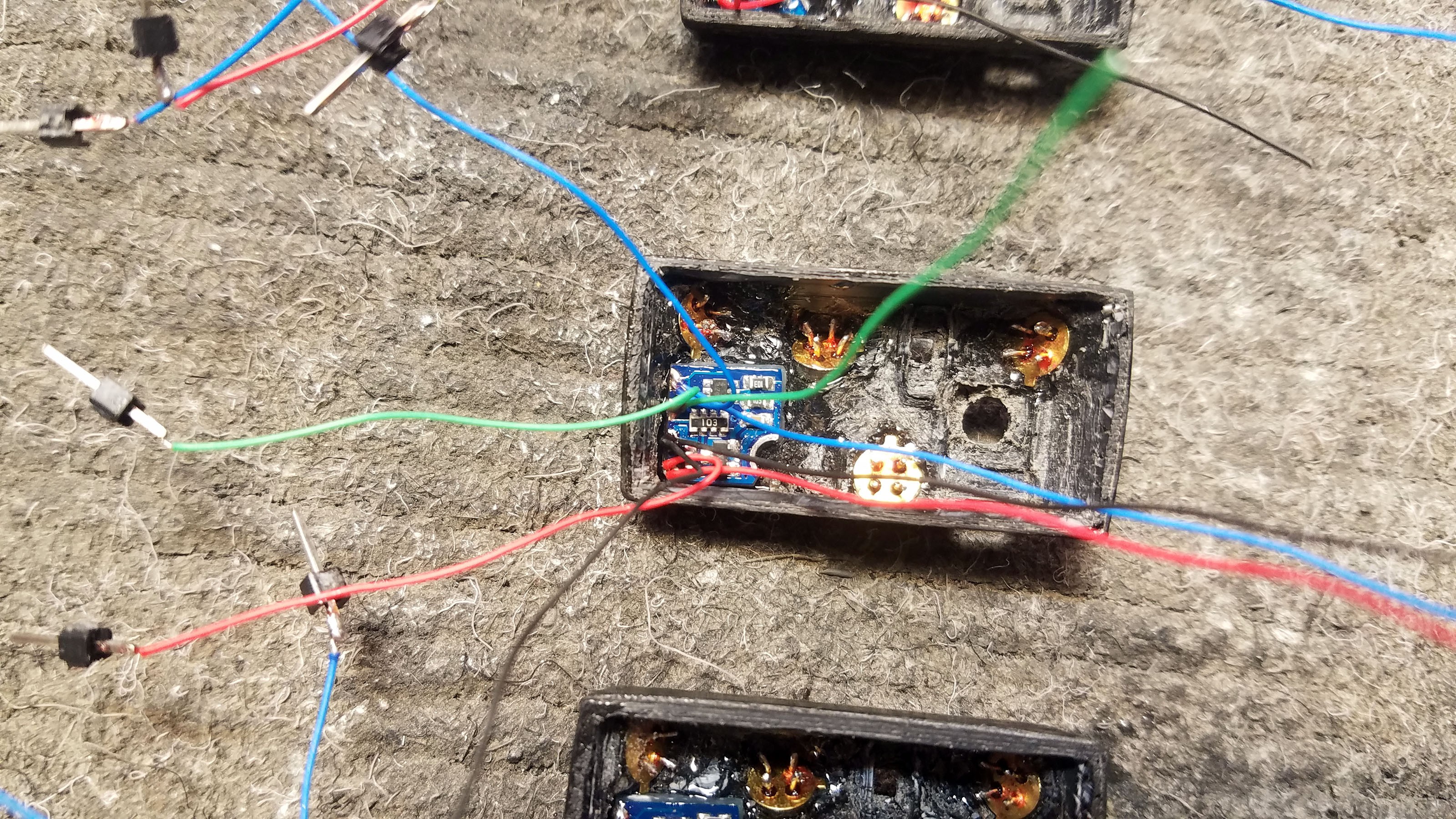
The VL6180 breakout fits into the sensor cap as shown. The actual sensor itself fits into the rectangular hole in the cap. The breakout is epoxied into the cap. Care is taken to ensure that excess epoxy does not get into the sensor itself.
![]()
VL6180 breakouts mounted in all four prototype sensor caps.
![]()
Another view.
19: Mounting the LED Breakout in the Sensor Cap
![]()
The LED breakout is mounted and epoxied into the sensor cap as shown.
![]()
Another view. I find that having the wire which conects to the PCB towards the center works best. The other end of the breakout will be connected to V+ (power), which I daisy chain across the thermal sensors.
![]()
Another view.
20: Mount Push Button in Sensor Cap
![]() This is a little tricky because the button will have a lot of force applied to it which means it has to be really firmly attached to the cap - but the button is also really easy to clog with epoxy. I usually epoxy the button to the enclosure in two stages: first with a small amount of fresh epoxy and second with a larger amount of epoxy that has hardened to the point of being a little sludgy.
This is a little tricky because the button will have a lot of force applied to it which means it has to be really firmly attached to the cap - but the button is also really easy to clog with epoxy. I usually epoxy the button to the enclosure in two stages: first with a small amount of fresh epoxy and second with a larger amount of epoxy that has hardened to the point of being a little sludgy.![]()
All components mounted in the sensor cap - bottom view.
![]()
All components mounted in the sensor cap - top view.
![]()
Aren't they beautiful? Take a deep breath because the next step is a doozy.
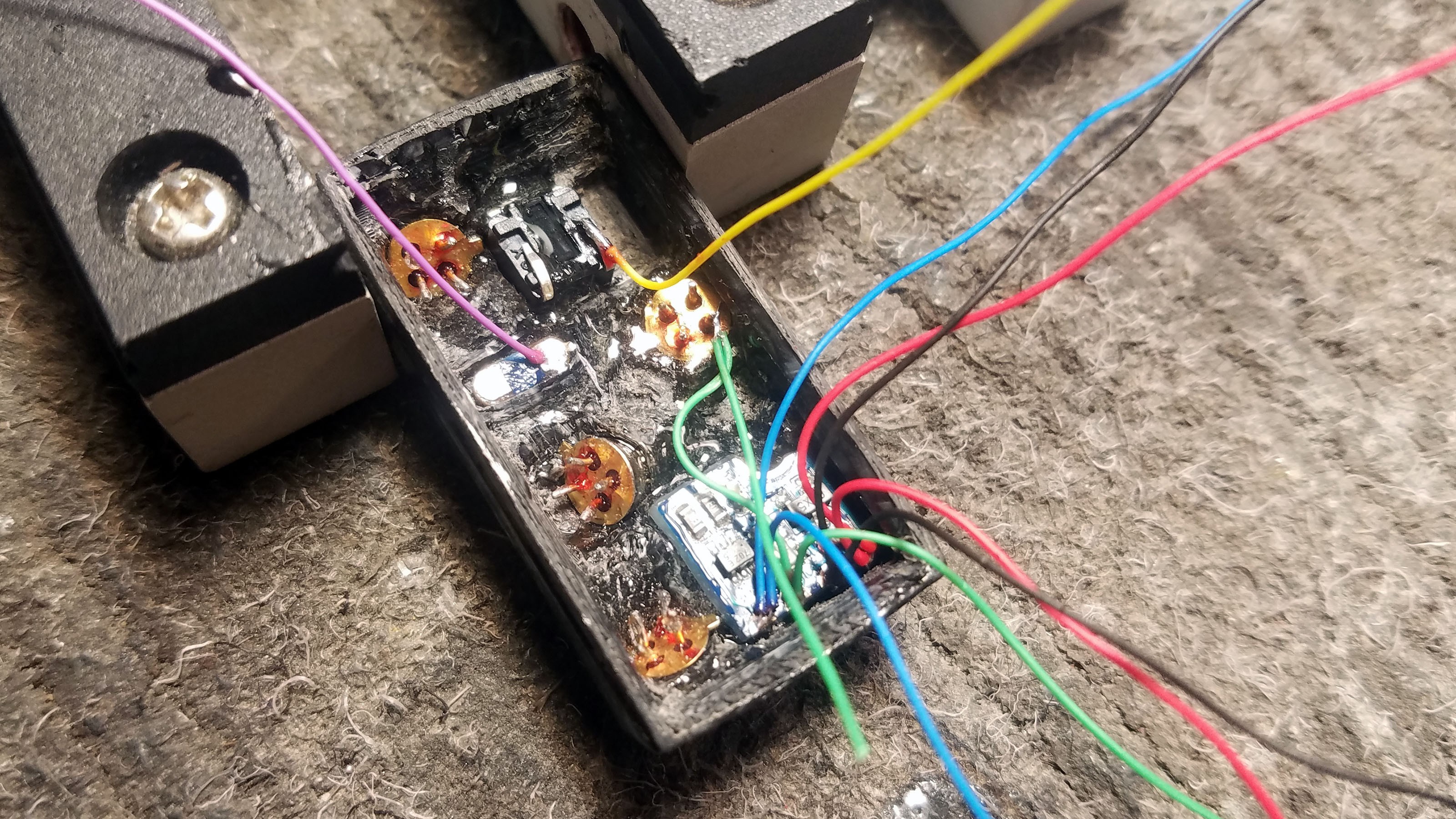
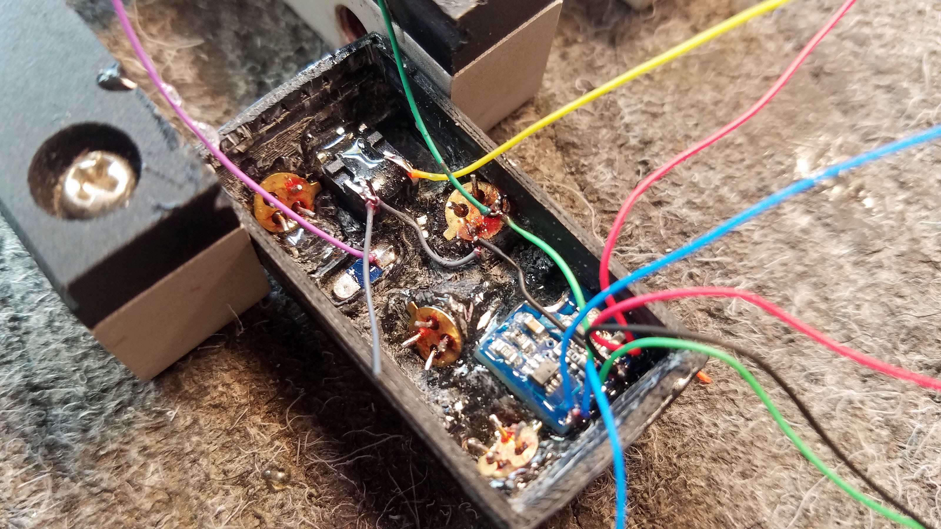
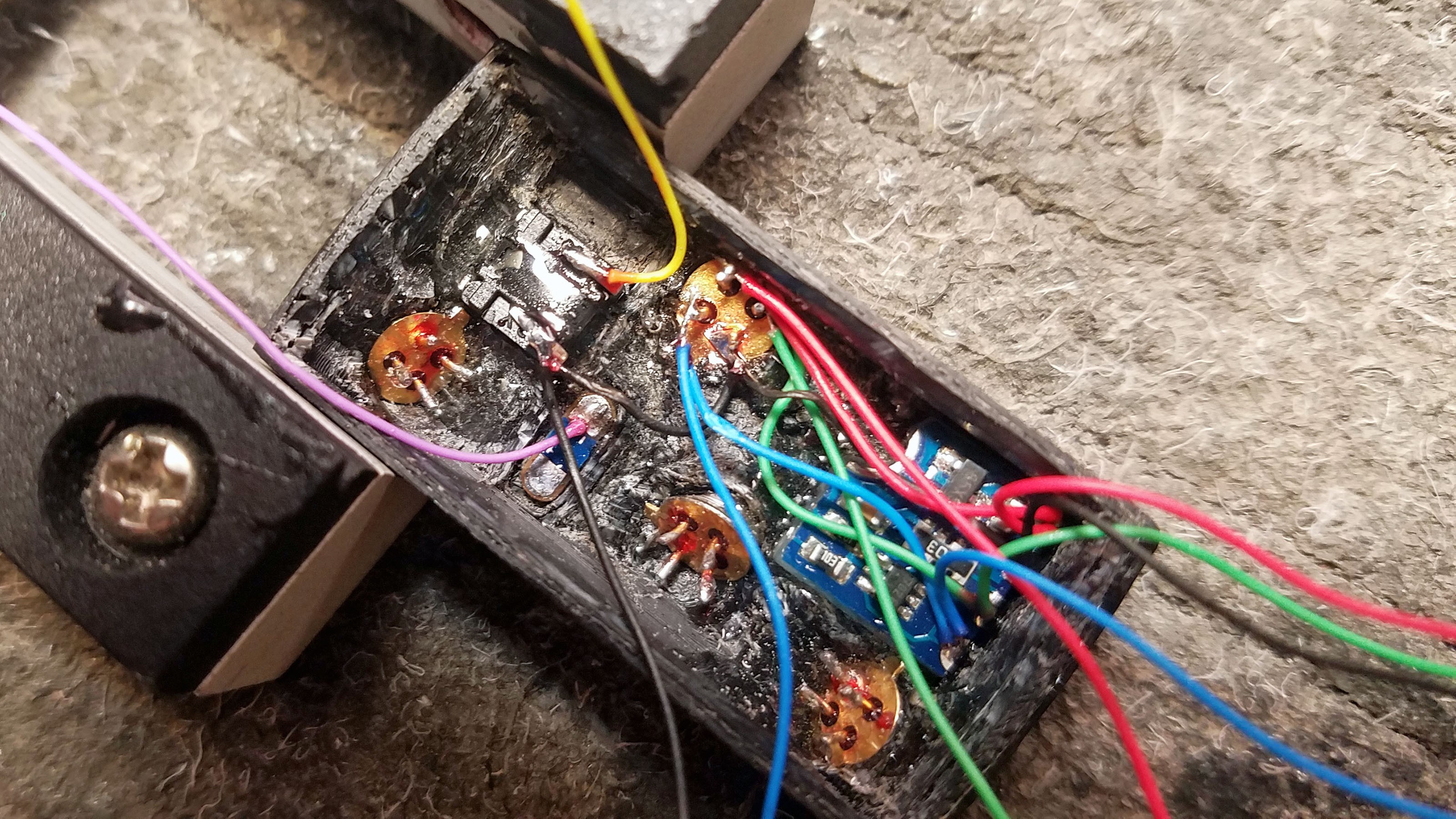
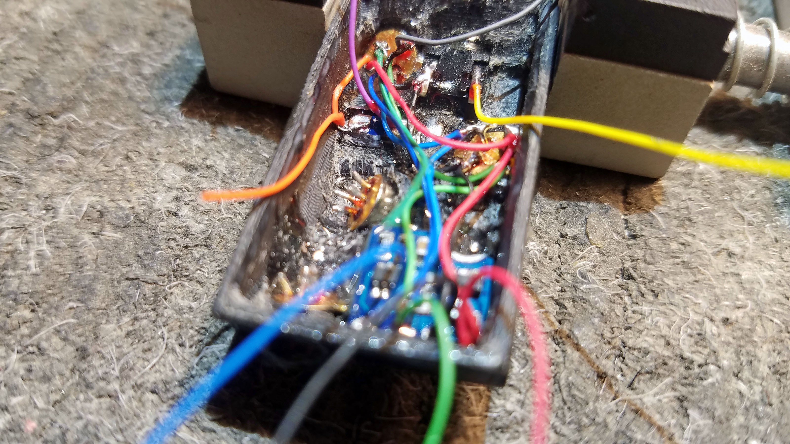
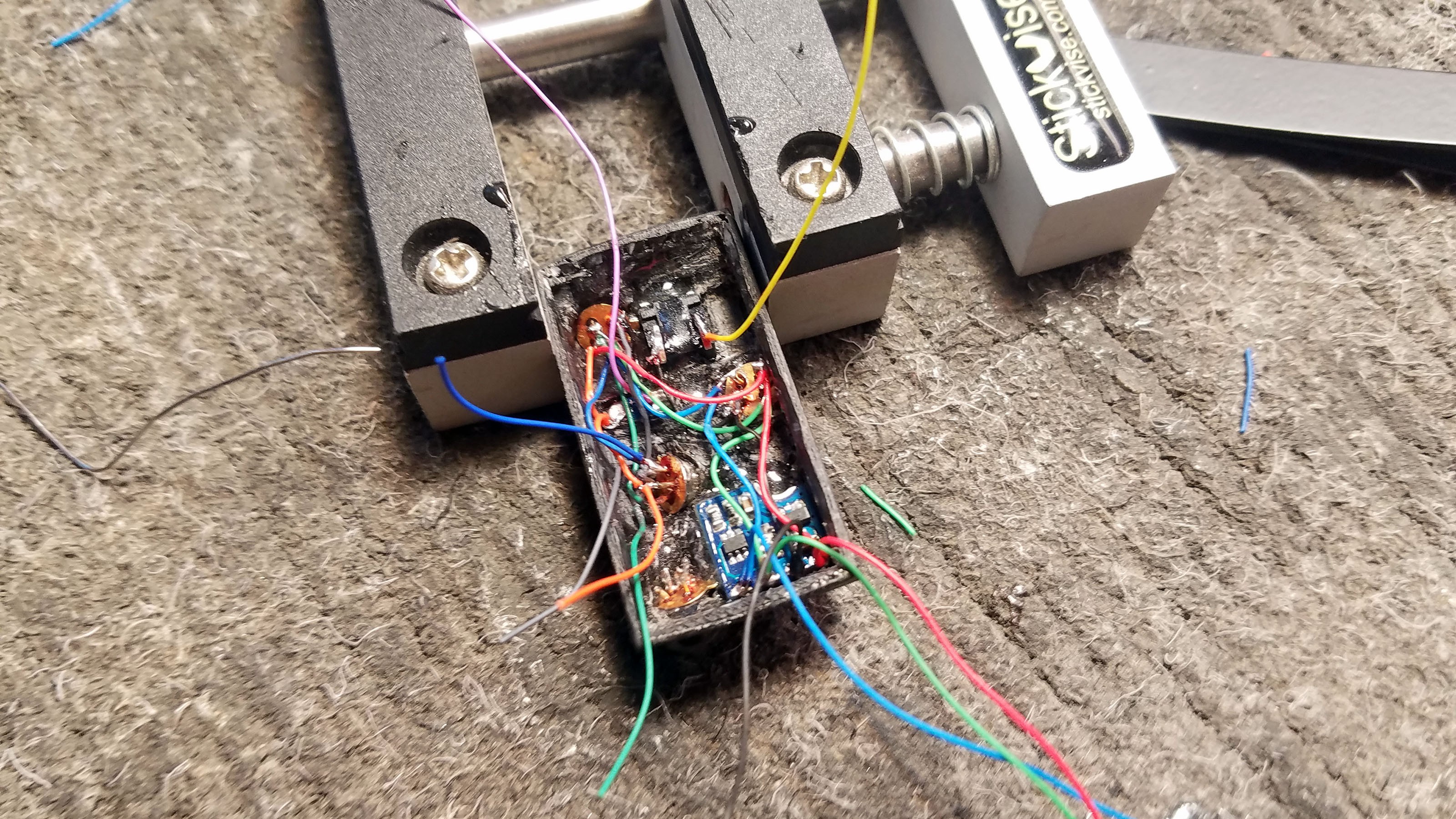
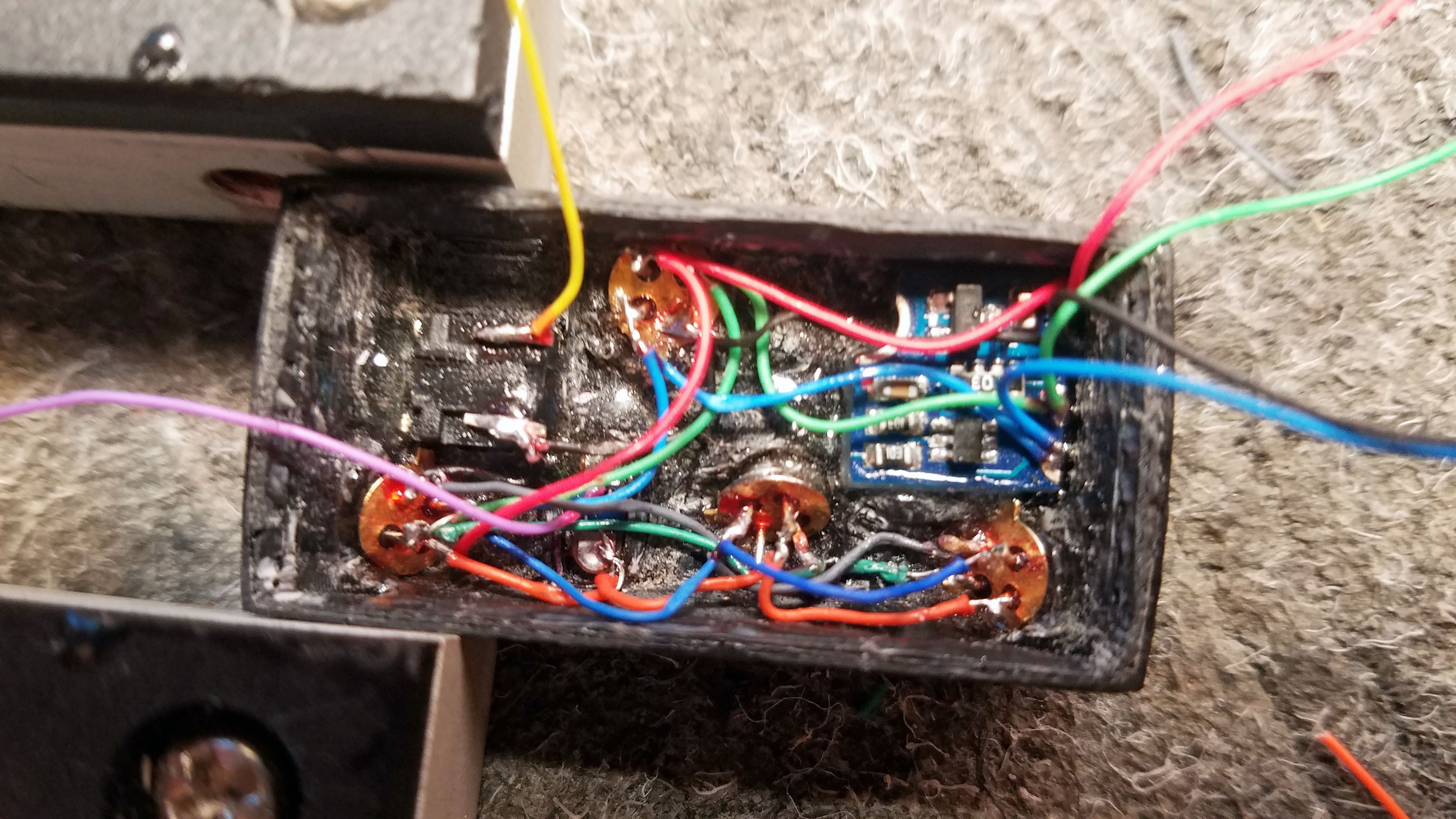
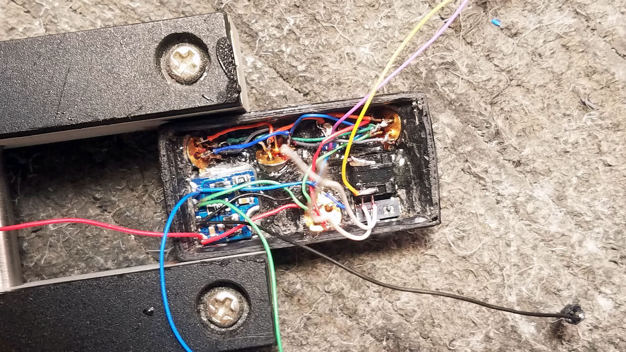
21: Sensor Cap Internal Connections
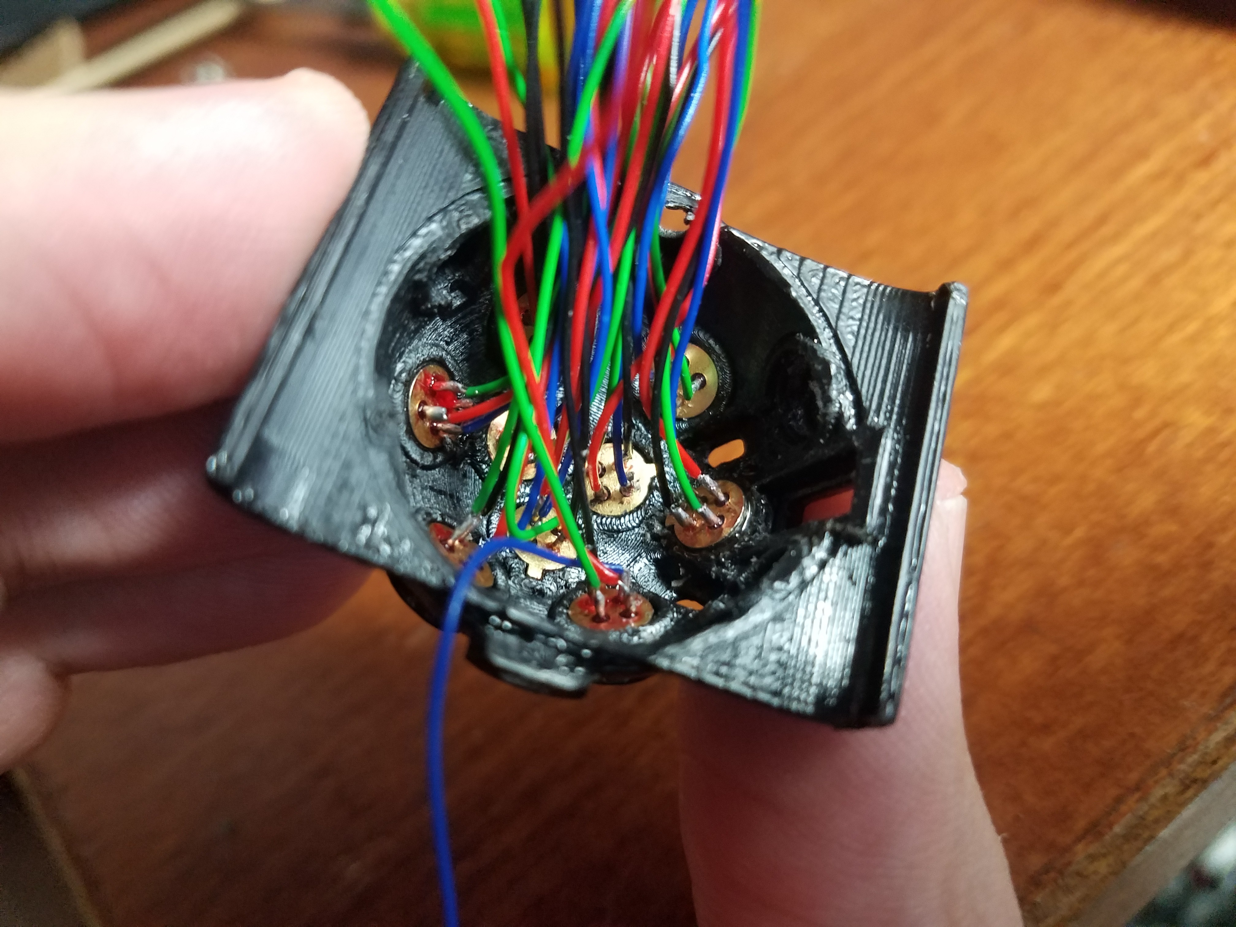
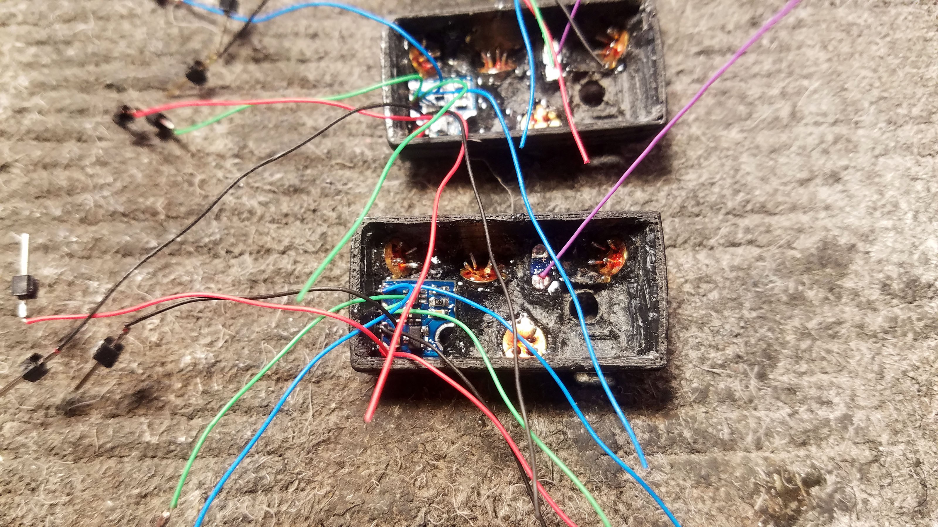
![]()
The VL6180 distance sensor and MLX90615 thermal sensors all run on the same I2C bus. This means that all the SDA, SCL, GND and V+ connections on all these sensors have to be connected with wires.
Green = SCL, Blue = SDA, Black = GND, Red = V+
![]()
Each thermal sensor has a little metal nub sticking out out of it. This is used to determine which pin is which. Above is from the MLX90615 data sheet.
![]()
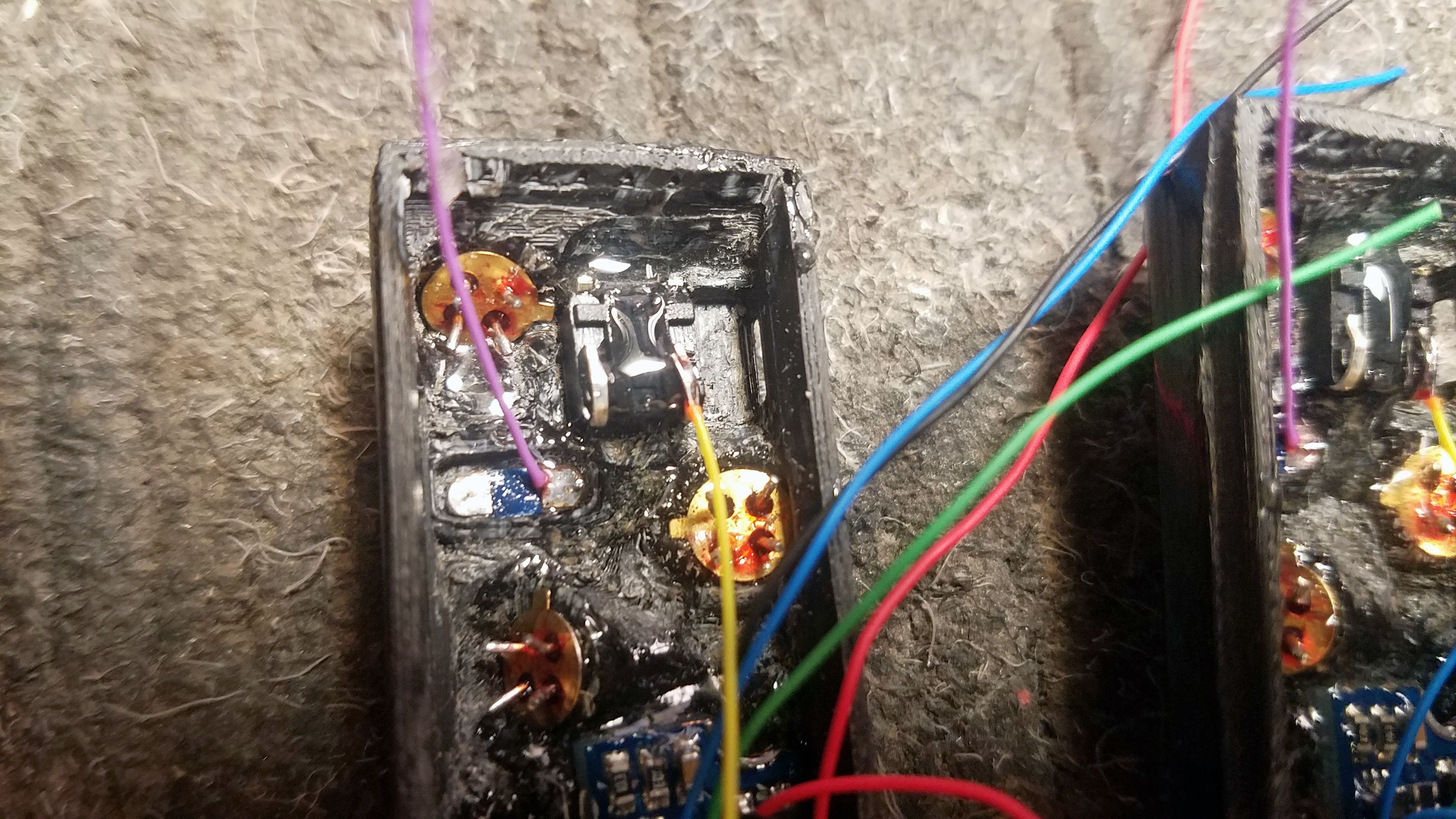
Connect SCL from the VL6180 to SCL on the front thermal sensor.
![]()
Connect GND from the VL6180 to GND on the front thermal sensor. Then connect GND from the first thermal sensor to the empty lead on the button.
![]()
Another view
![]()
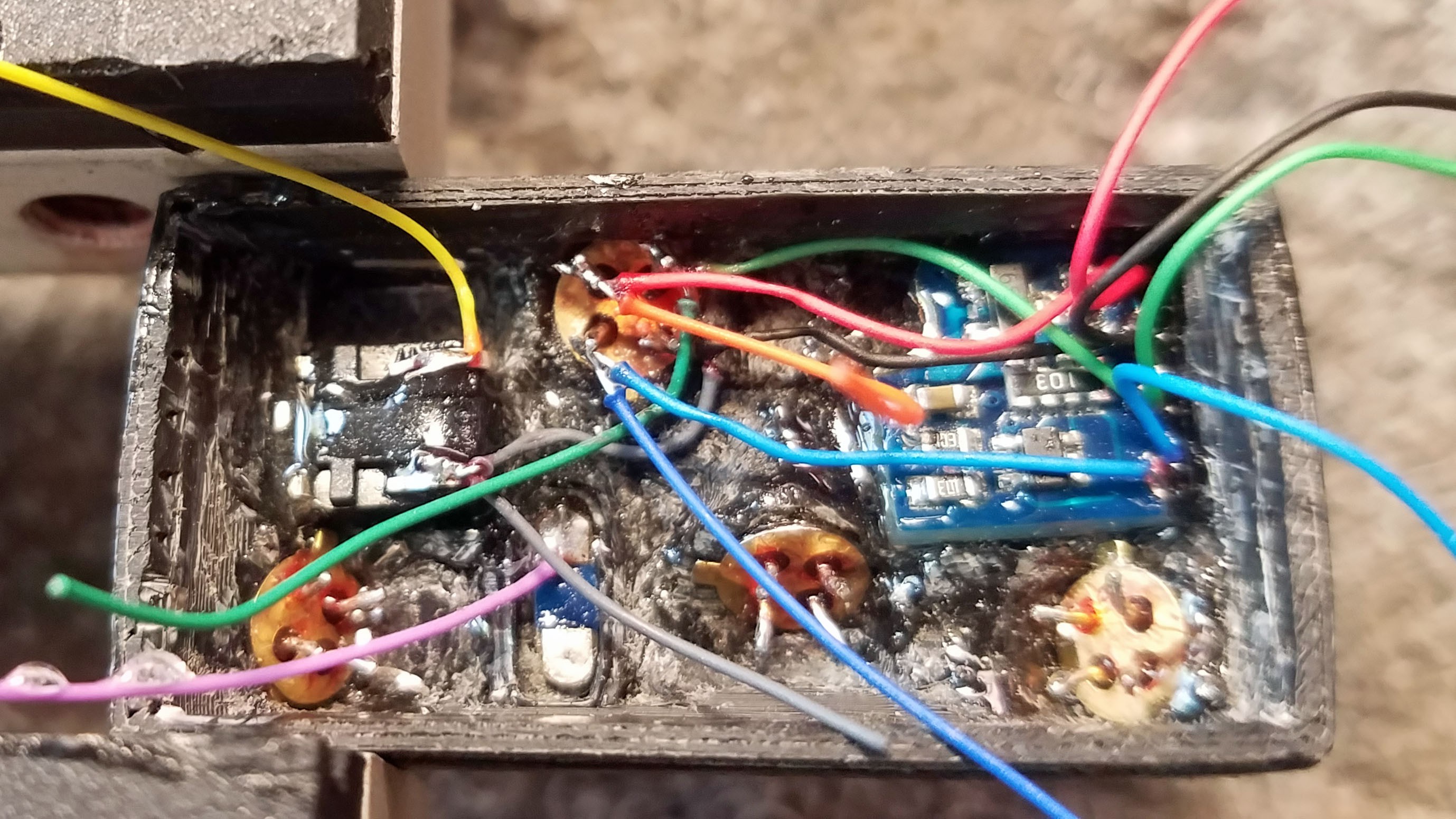
Wire the rest of the connections between the VL6180 and the front thermal sensor.
![]()
Another view. Each time I make a connection, I solder two wires, not one. I trim the wire I am going to make a connection with, strip the end, strip another wire and twist the ends together. Then I flux and solder the tips together. Because everything is pre-soldered, I don't have to apply any additional solder when I attach the wire-pair to the sensor lead (or button or LED breakout). All I do is press the tip of the wire pair against a sensor lead (or whatever) and quickly apply just enough heat to fuse together the solder which is already on the wires and sensors I am trying to connect.
![]()
Another view.
![]()
The VL6180, front thermal sensor and left thermal sensor (orientations as they appear on a completed prototype pointed away from a user with sensor cap pointed up) have been connected. In the picture I am holding a wire pare from V+ against the "+" side of the LED breakout for soldering.
![]()
V+ from the left thermal sensor has been connected to the LED breakout with a wire pair.
![]()
Another view.
![]()
Connecting the left thermal sensor to the center thermal sensor.
![]()
Another view.
![]()
Another view.
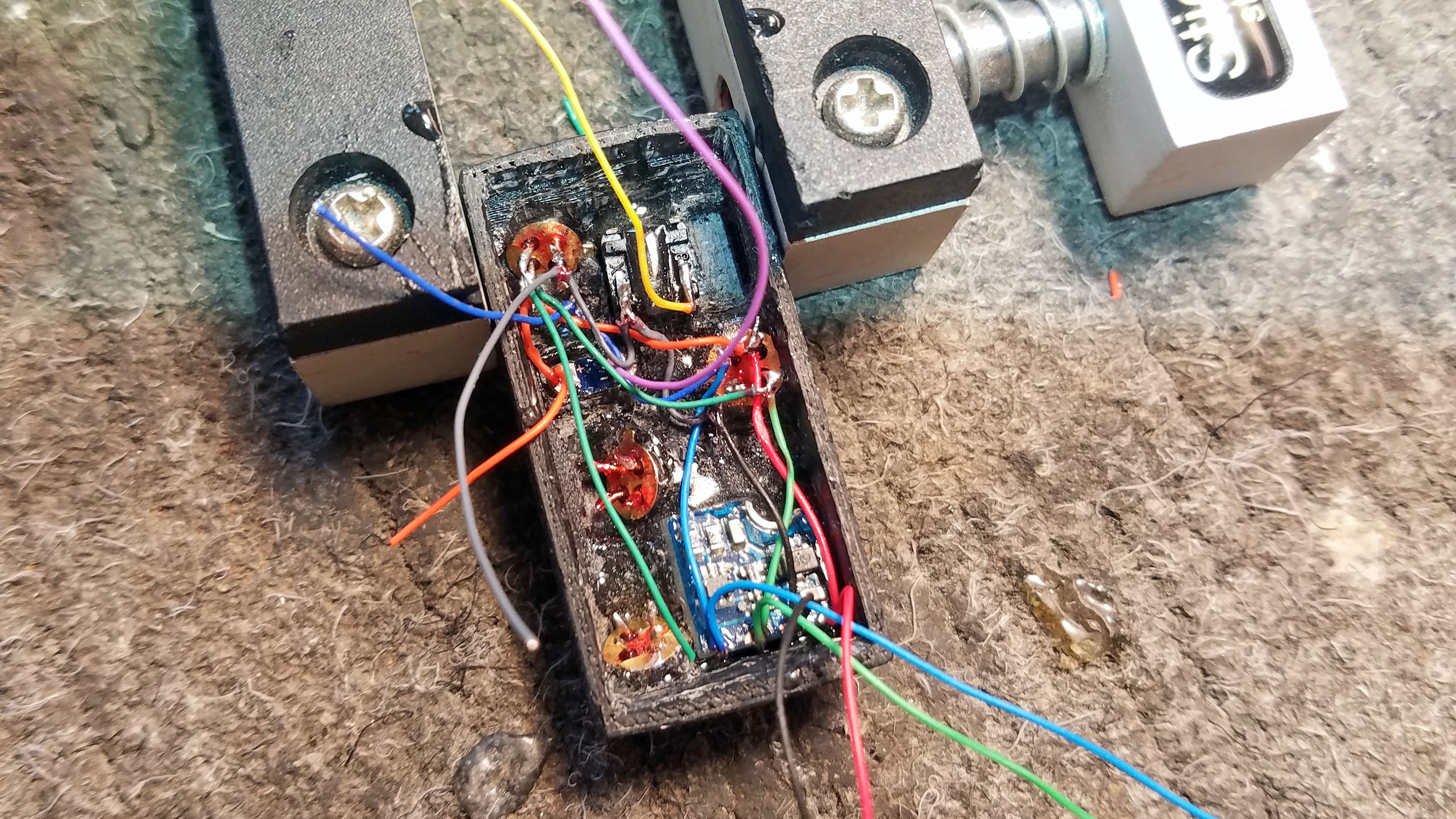
![]()
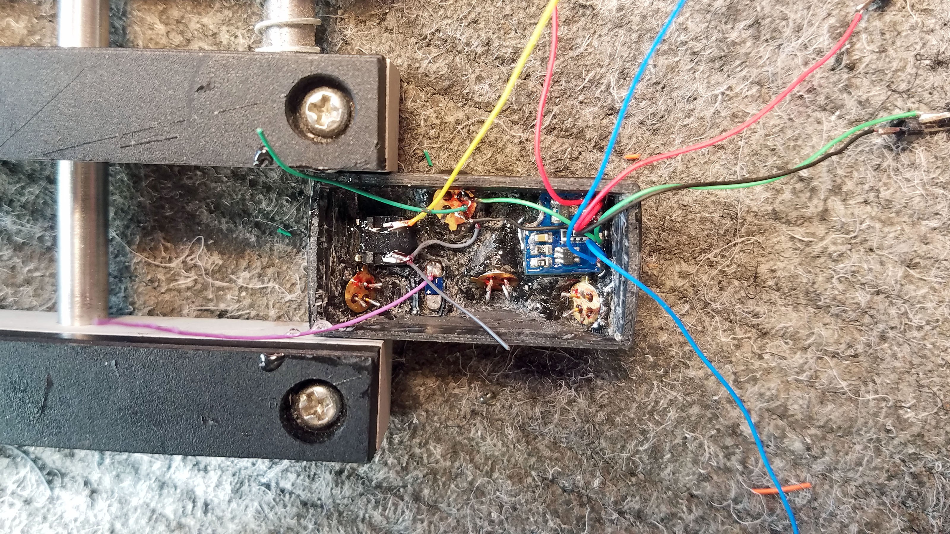
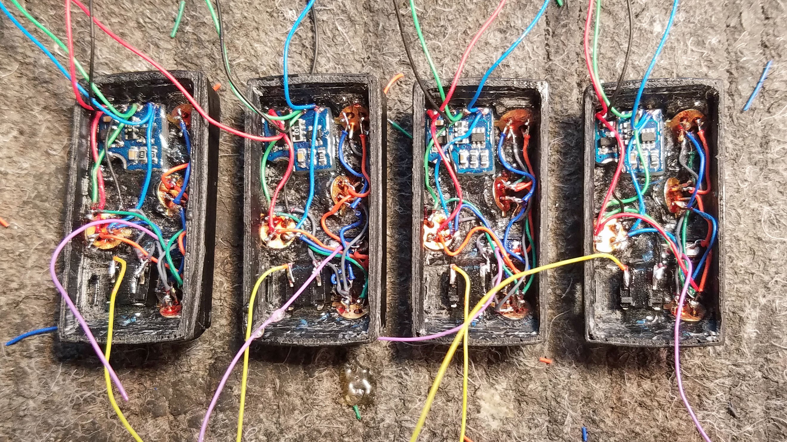
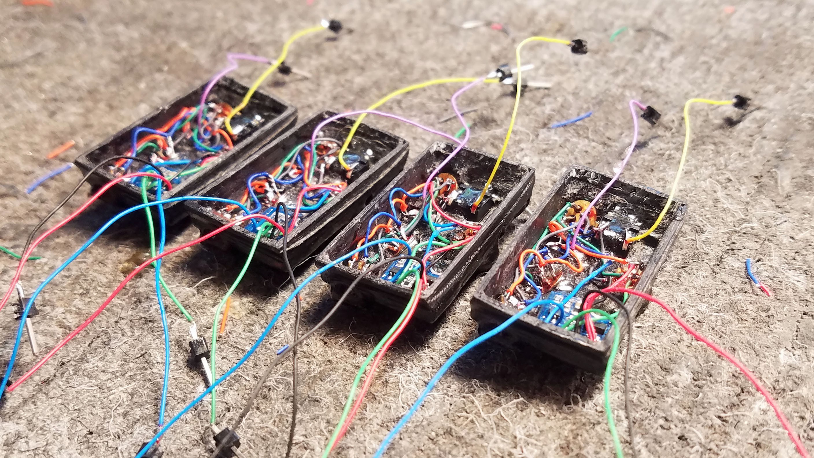
All connections complete.
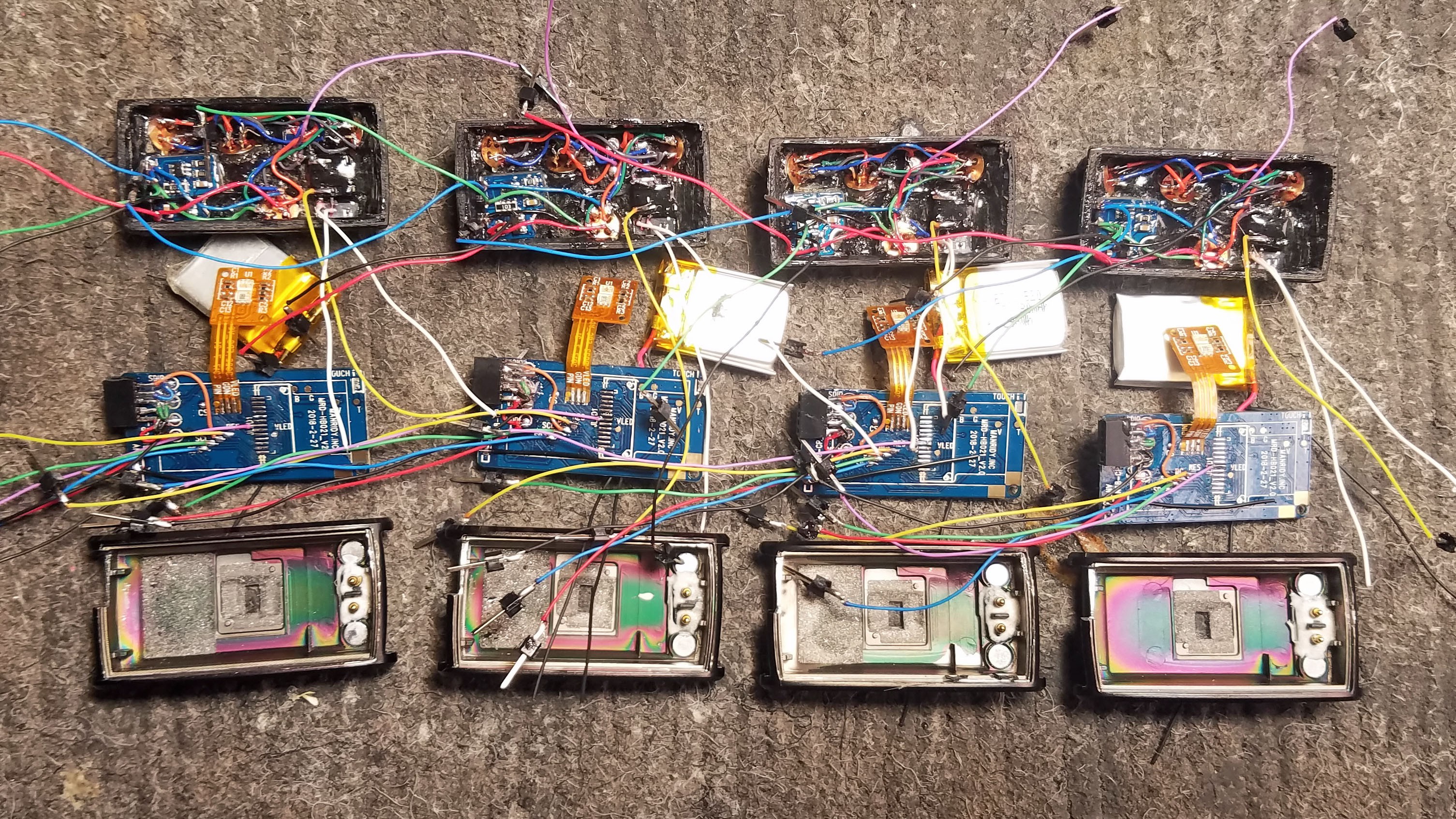
![]()
All connections complete for all four prototypes.
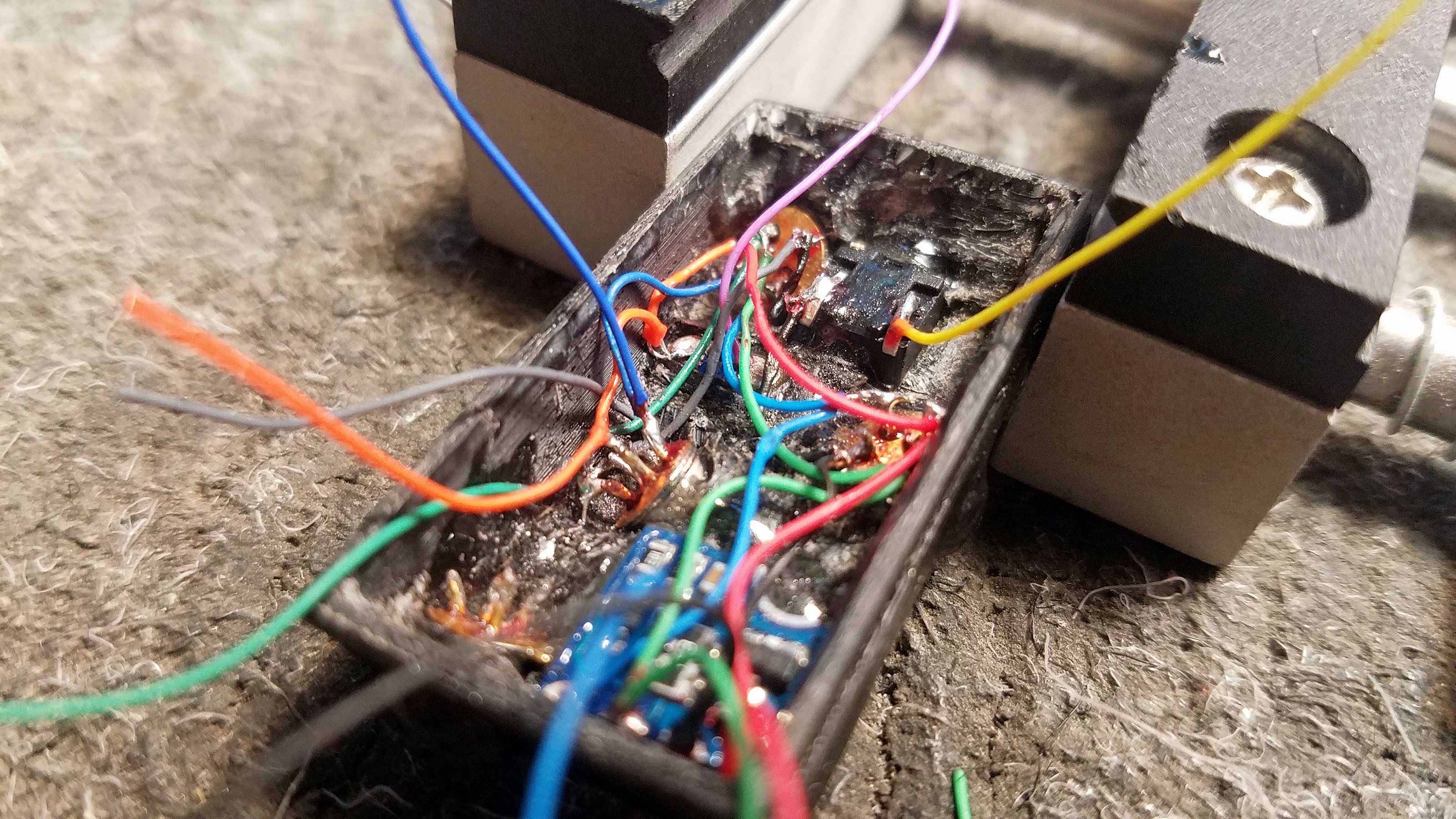
![]()
Another view. Its all downhill from here - assuming nothing got screwed up.
22: Testing the Completed Sensor Cap
![]()
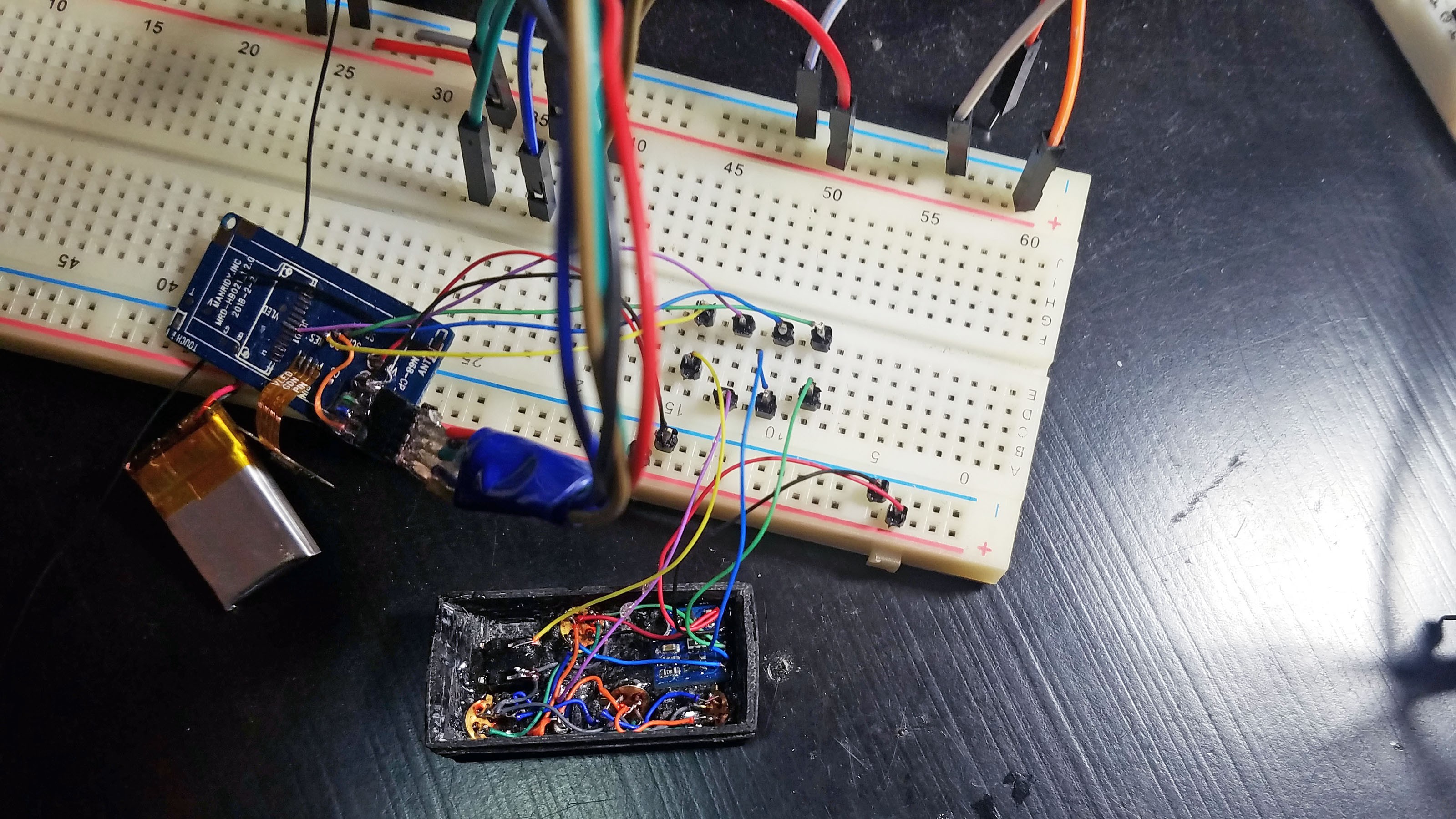
If I'm going to make a mistake anywhere, its going to be the internal connections on the sensor cap. At this point bread-boarding the entire prototype is as easy as connecting the wired up N68 PCB to the sensor cap leads (the second set of wires from the VL6180). I test everything with the production firmware I use to run these prototypes in the wild (hand off to test users).
23: Mount Battery Switch in Sensor Cap
![]()
The mini SMD switch is epoxied into place in the sensor cap. Care must be taken so that the epoxy doesn't clog the switch. This step is so easy compared to wiring up the sensor cap sensors that I consider the cap complete before I even mount the switch - as long as it tests out.
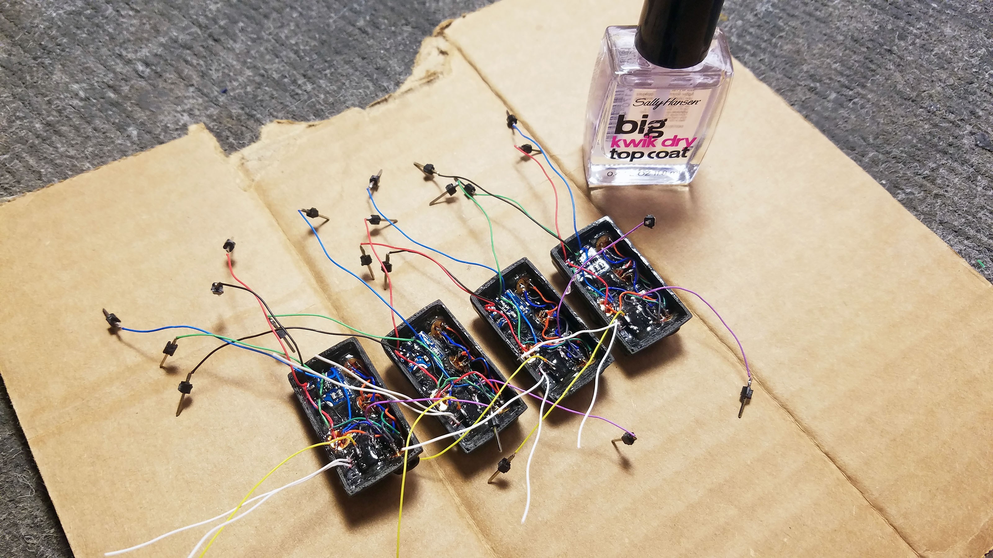
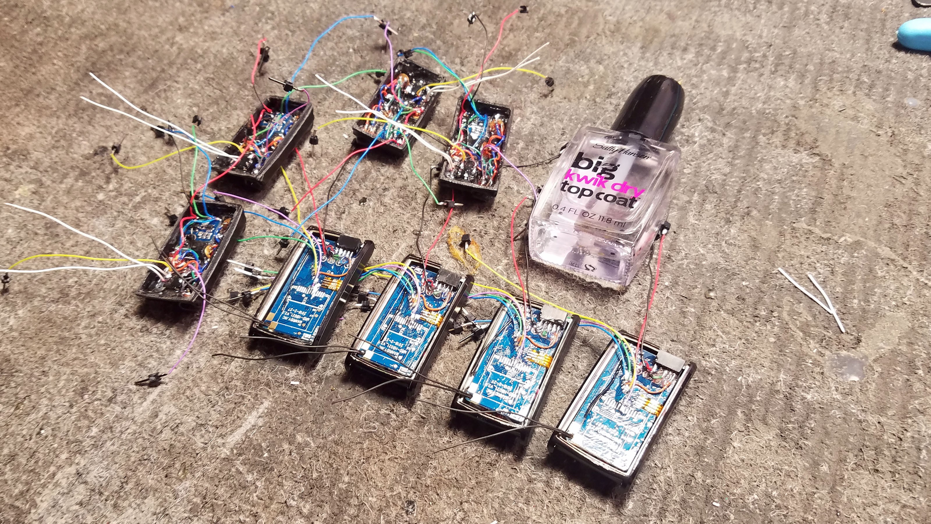
24: Coat Everything With Nail Polish
![]()
Nail polish is great. It acts as an insulator most importantly. It also strengthens everything. Unlike epoxy it is easy to remove. Once everything in mounted in the sensor cap I coat it all with clear nail polish. I also coat the N68 PCB.
![]()
Everything nice and shiny with a top coat of nail polish.
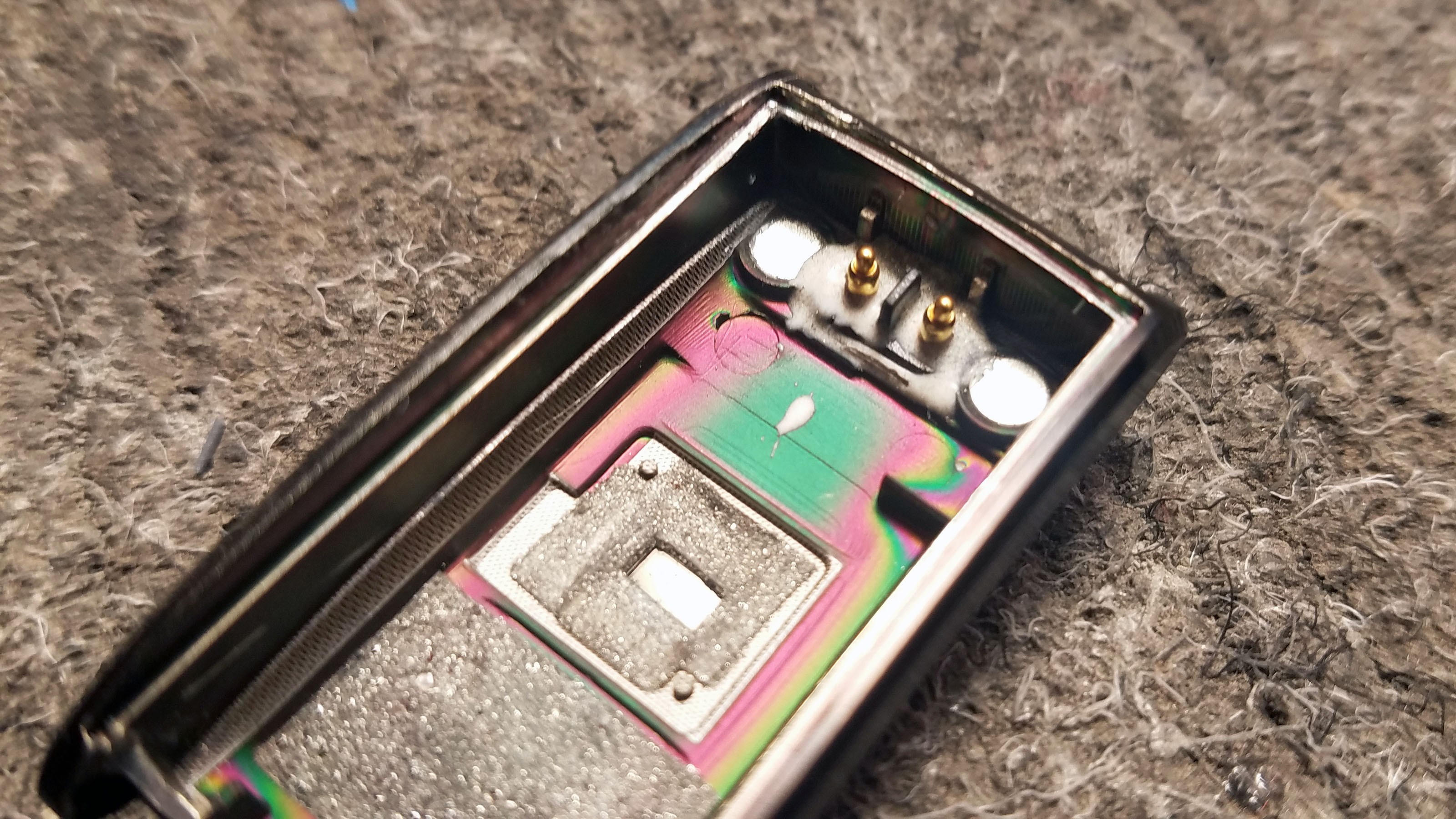
25: Hard-wiring Battery Charger Connections
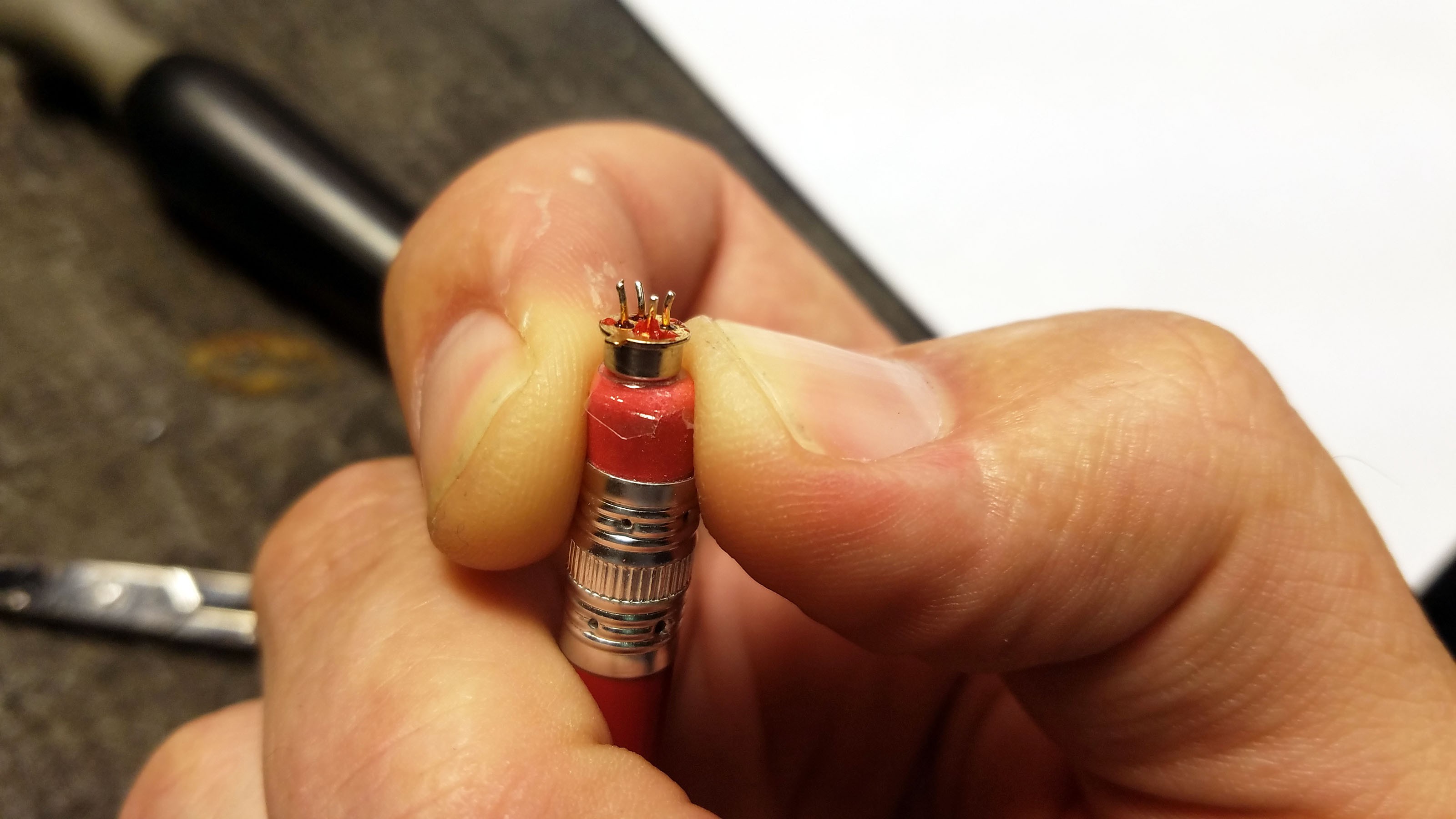
![]()
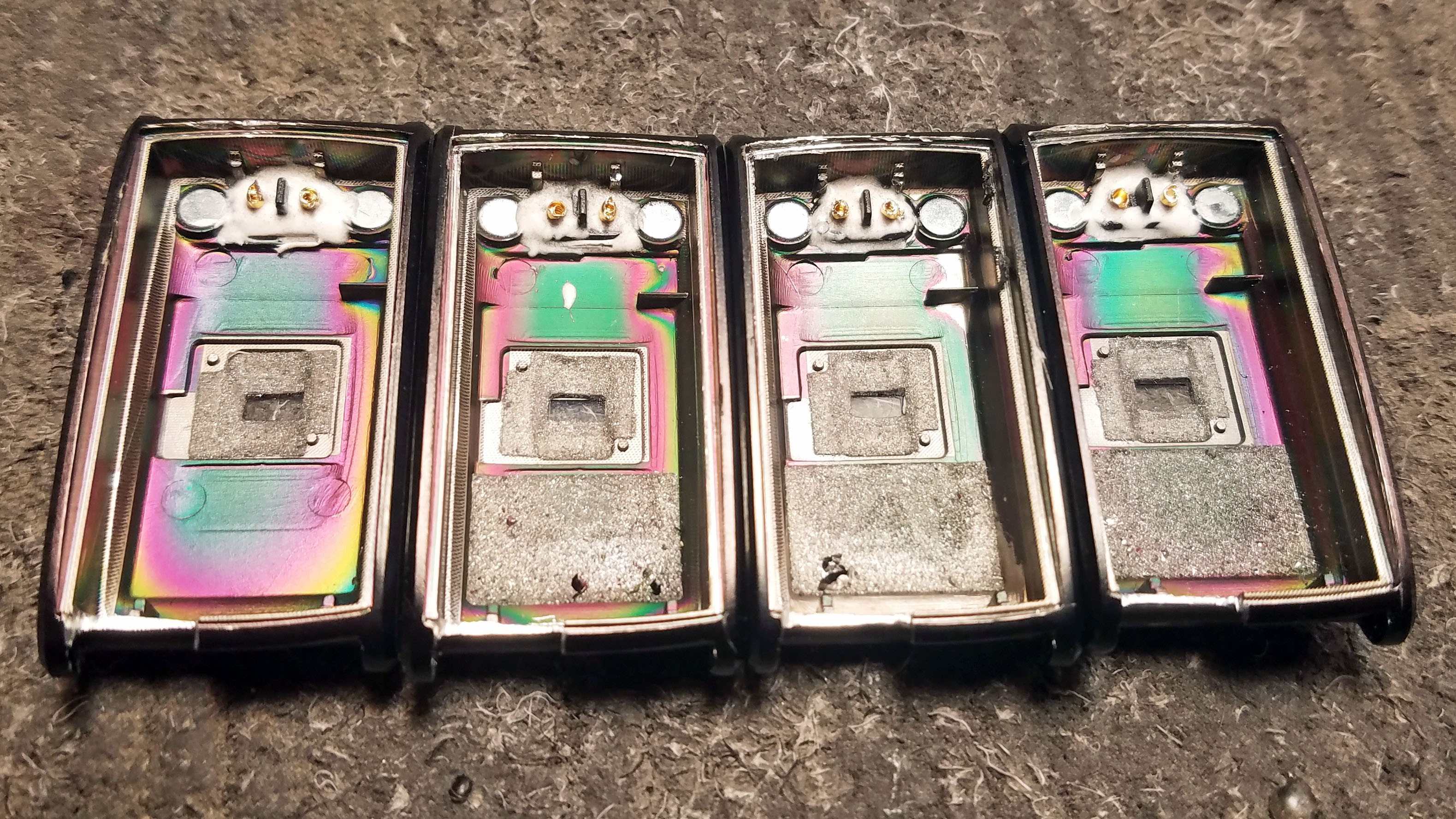
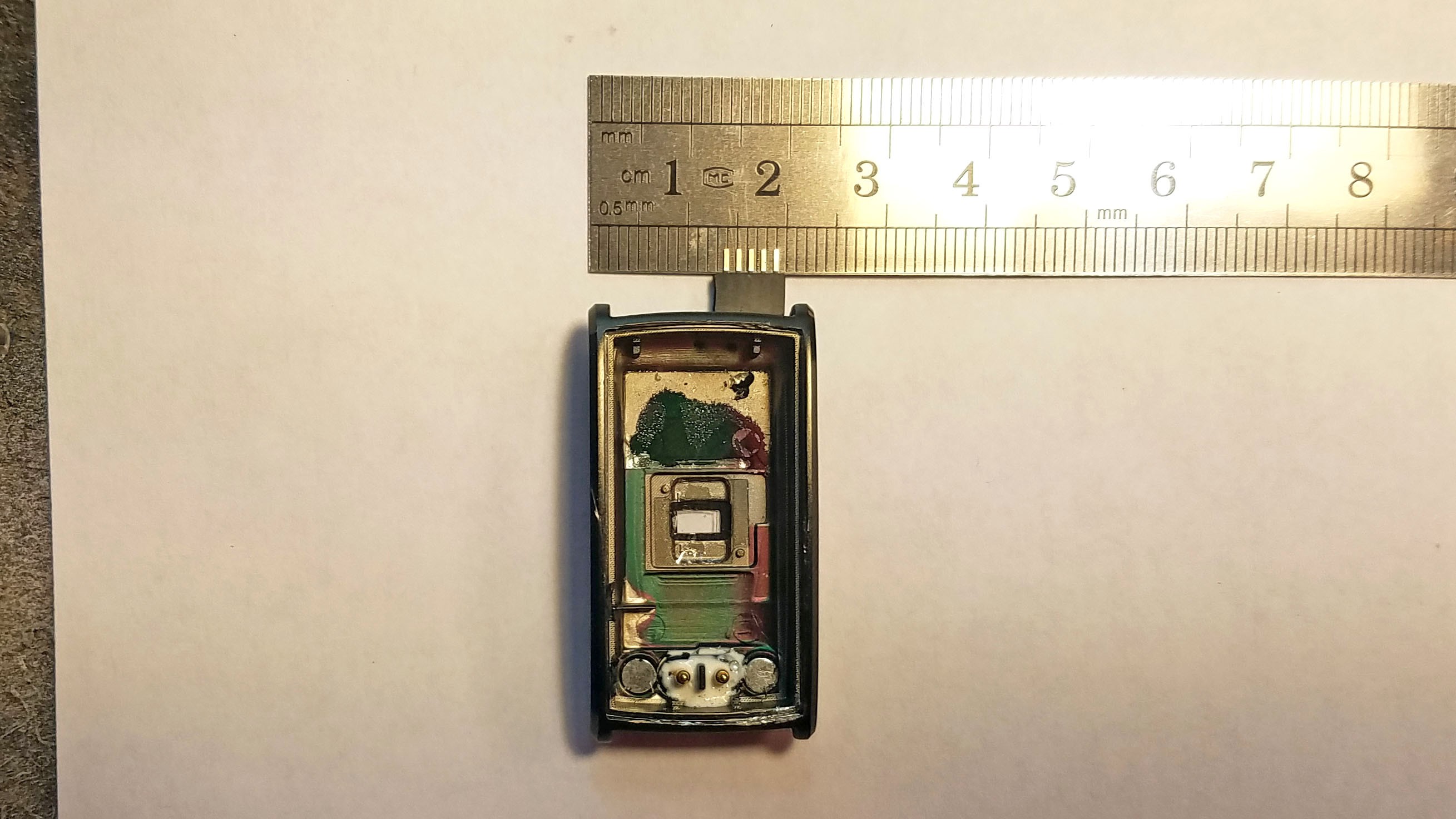
The N68 fitness tracker has a lovely magnetized battery charging outlet mounted in the metal enclosure bottom. You can see the magnets to either side of the pins above. Those two pins are spring loaded and press against the main PCB. This is a design bug in the N68 fitness tracker itself. This fitness tracker will often stop working because the above pins do not press against the PCB hard enough, or because oxidation blocks an electrical connection. I get around this by hard wiring the charger outlet to the PCB contacts.
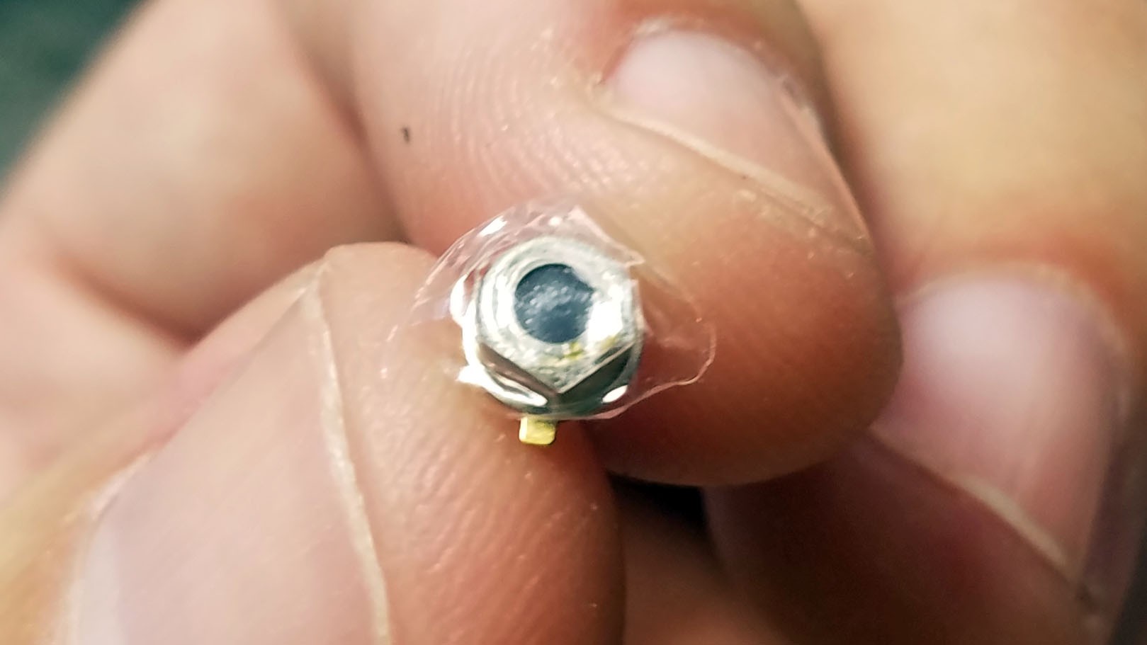
![]()
Here I've chopped off the tops of the pins with wire snips.
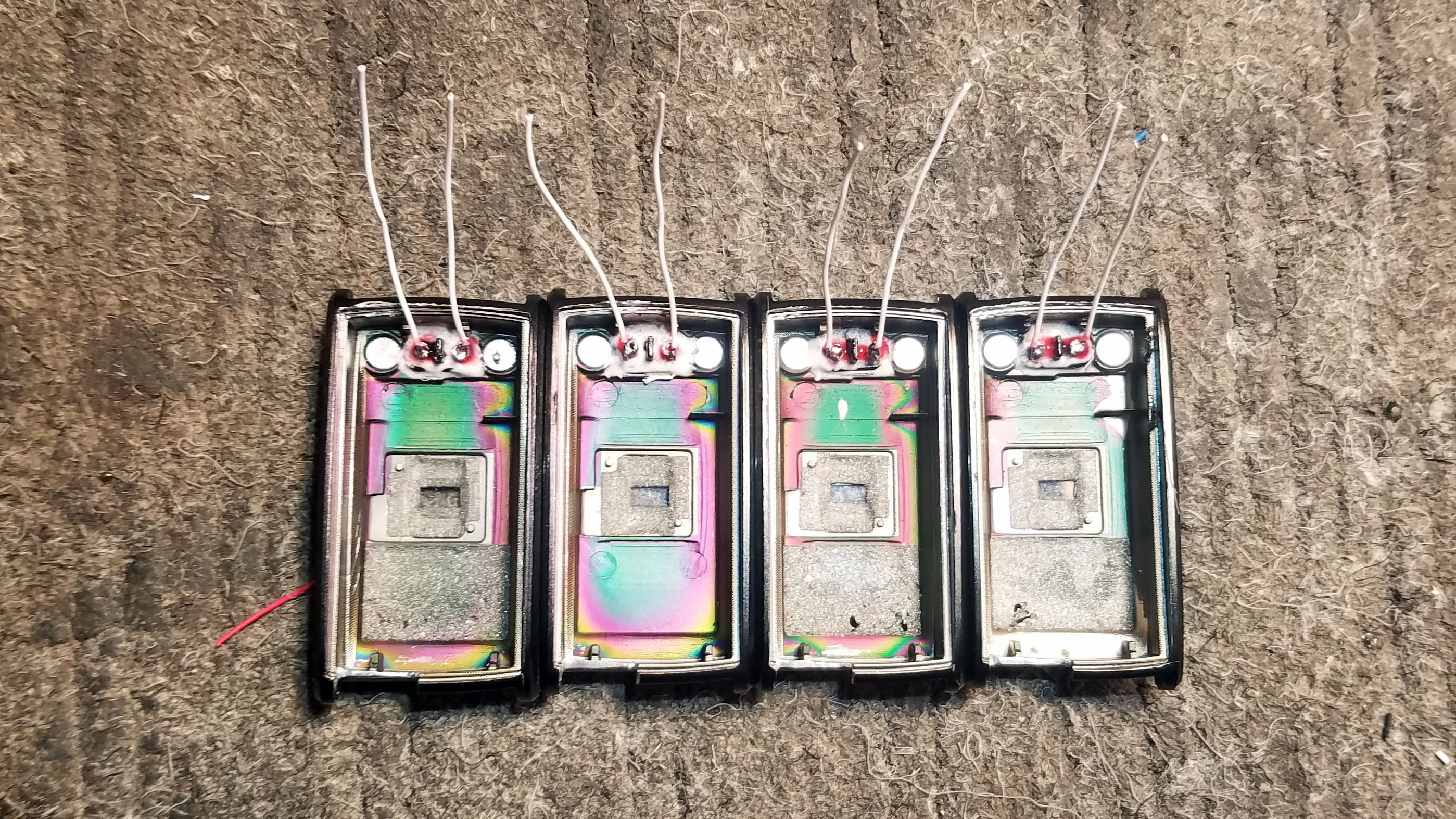
![]()
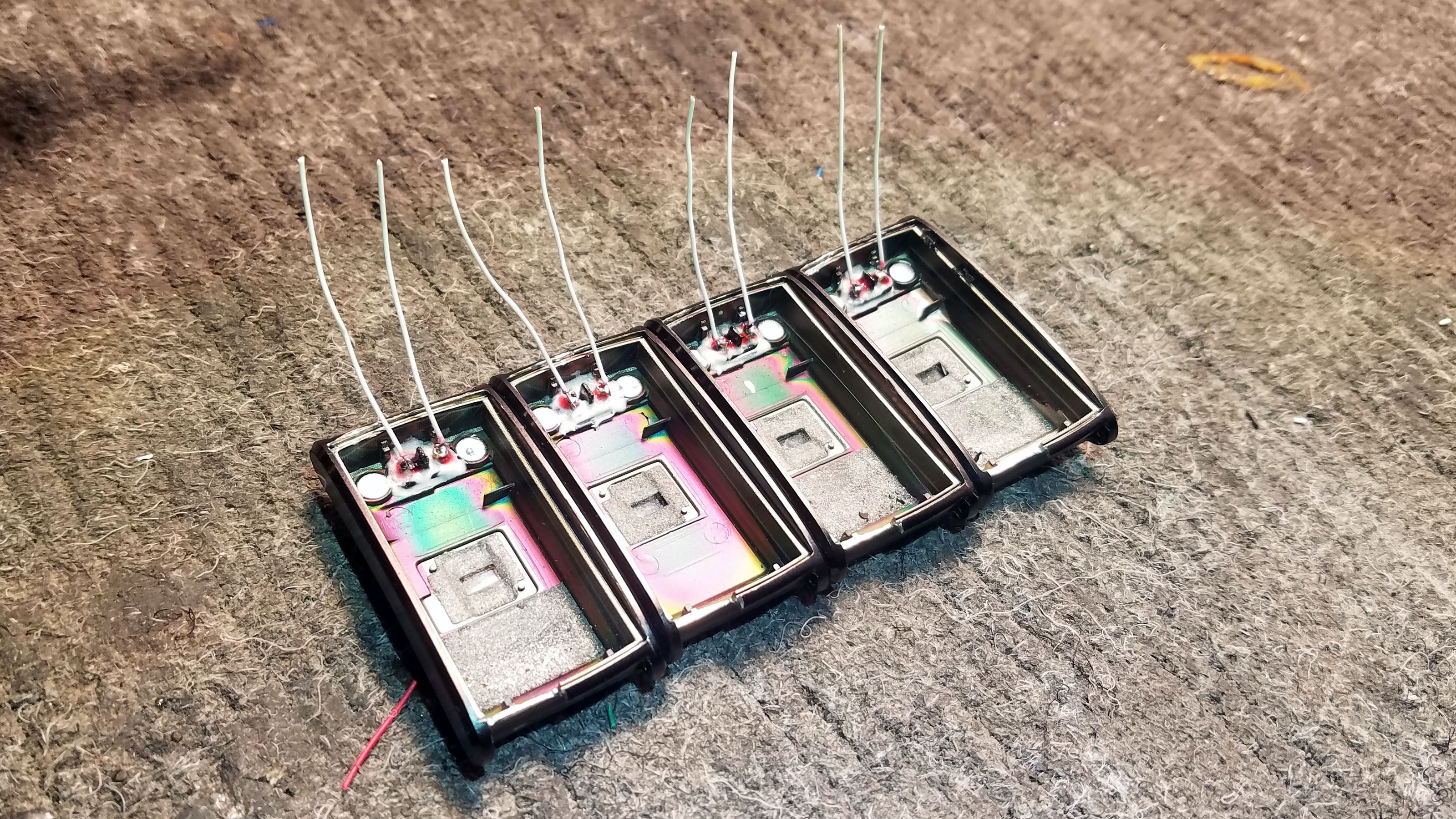
I solder wires to the pins.
![]()
Another view.
![]()
The wires from the battery charger outlet are trimmed and soldered to the PCB.
![]()
All four PCBs and metal enclosure bottoms with charger outlets soldered to PCBs.
![]()
I bend the wires to the sides even before I solder so that the PCB will fold cleanly into the enclosure.
26: Reinforcing the PCB and Programming Connector
![]()
I apply epoxy to all solder points on the PCB to strengthen it.
![]()
I apply additional epoxy around the programming connector to strengthen it.
![]()
All four prototypes with fortified PCBs.
27: Final Coat of Nail Polish
![]()
I add another coat of nail polish to the inside of the sensor cap and the top of the PCB. When these are joined to each other, pressure will be applied to connections in a fashion which is not always predictable. Taking precautions insures that there will be no issues when the sensor cap and PCB and sandwiched together.
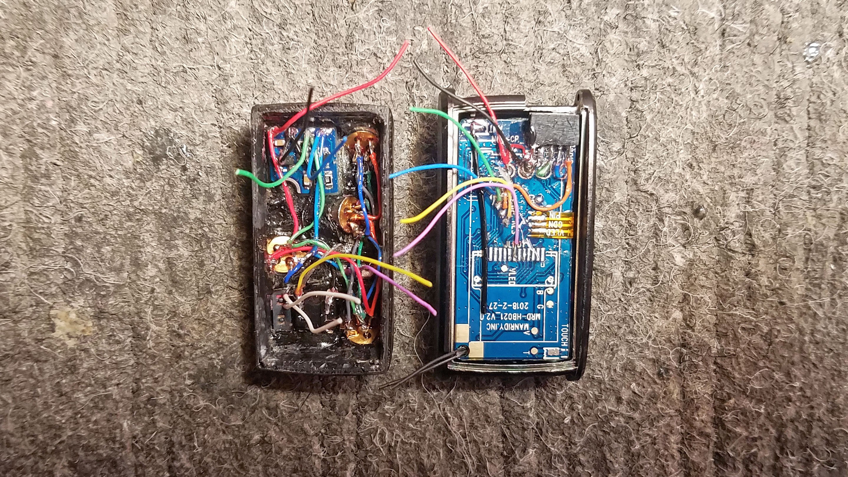
28: Connecting the Sensor Cap to the PCB
![]()
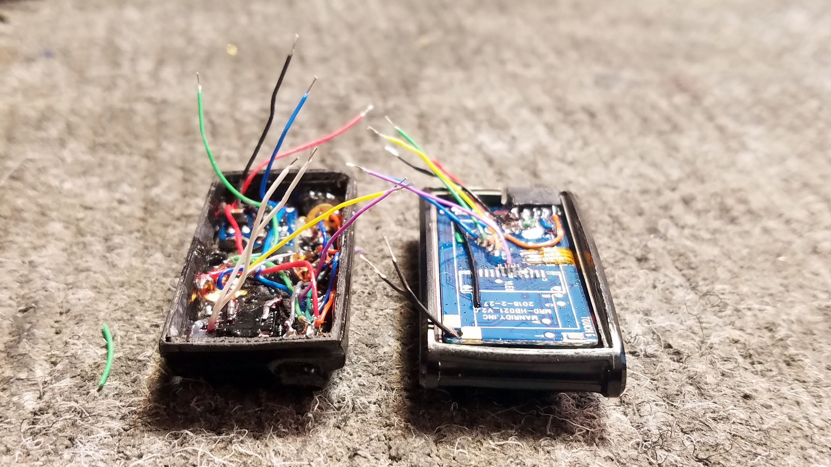
Wires on sensor cap and PCB are trimmed.
![]()
Another view.
![]()
Wire tips are striped, fluxed and pre-soldered.
![]()
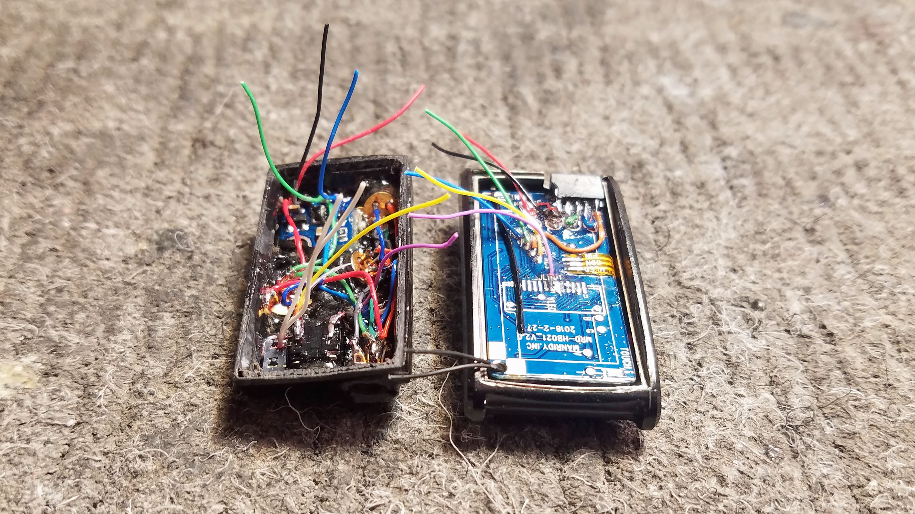
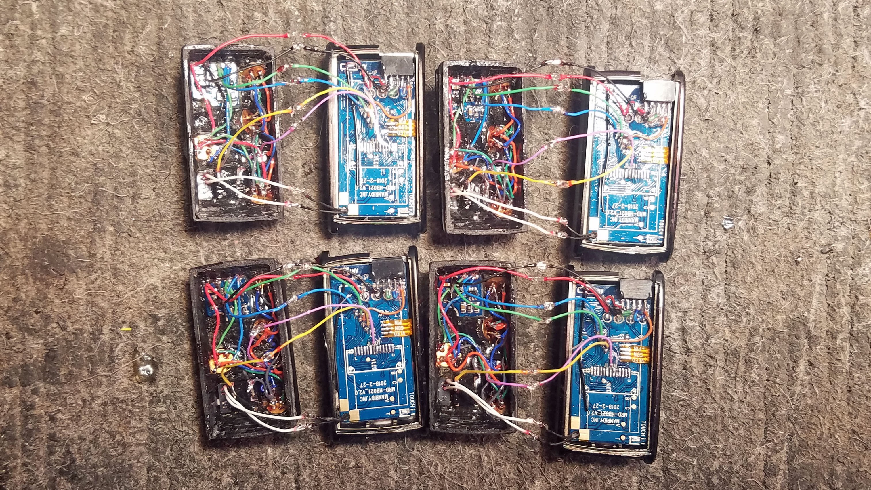
Wires are soldered together. Everything should be color coded at this point.
![]()
Another view.
![]()
All four sensor caps and all four PCBs connected.
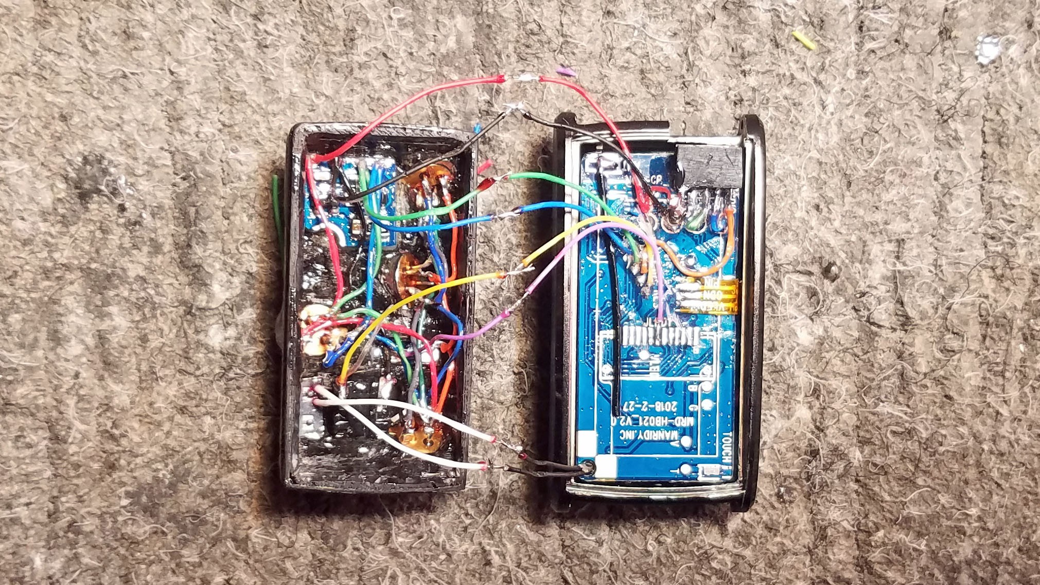
![]()
Another view.
![]()
Another view.
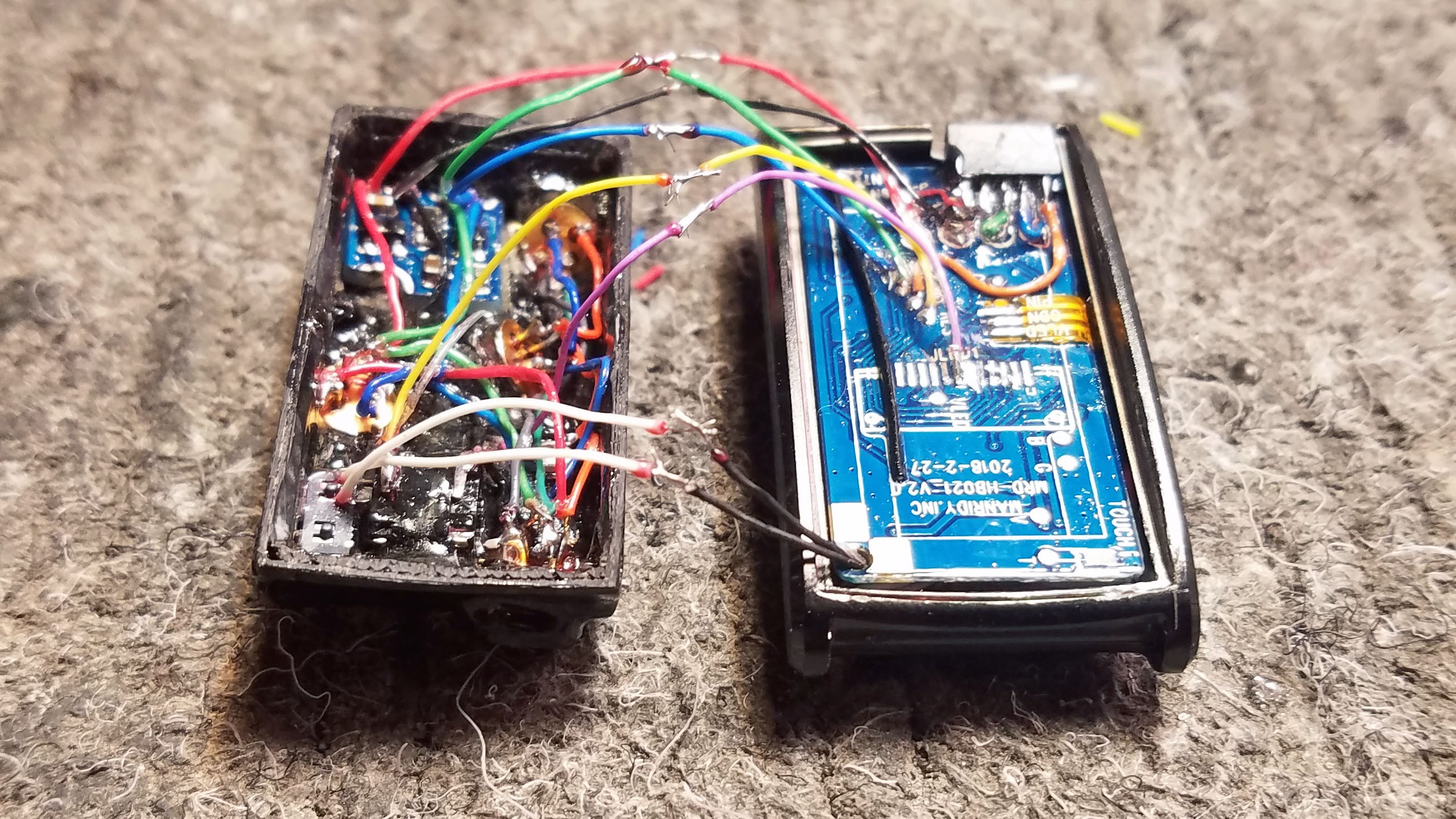
![]()
Connection points are reinforced with epoxy - you can see it beading a little where the wires are soldered together.
![]()
All four prototypes with epoxy reinforced connections.
29: Testing Before Closing Cap
![]()
Each prototype should be tested again at this point.
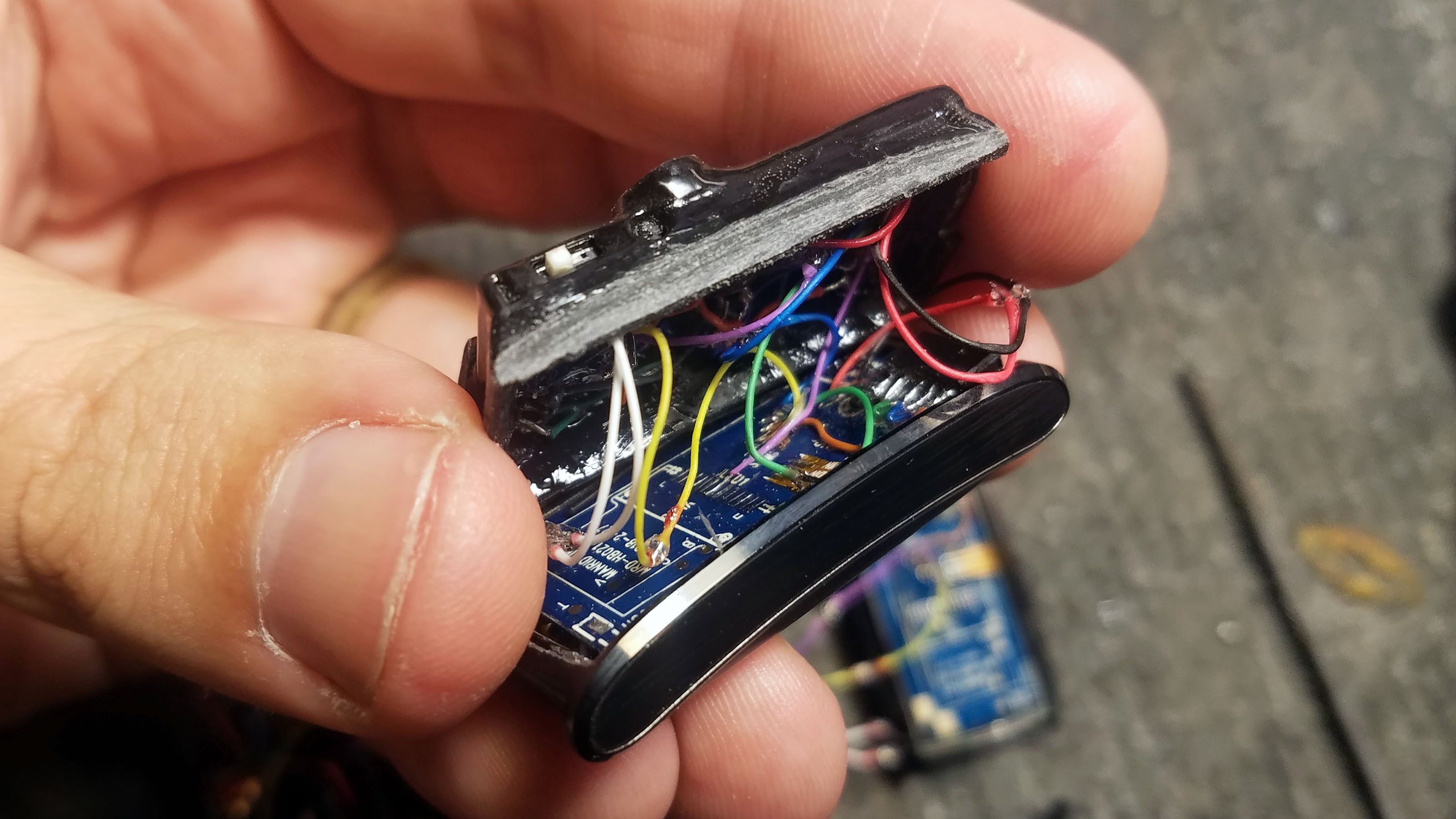
30: Closing Sensor Cap
![]()
The 3D printed sensor cap has been modeled to fit perfectly into the metal part of the enclosure. This works really well, I've never had any issues.
![]()
I sand the areas that will fit against metal (the sanded plastic is a little lighter in color that the rest of the plastic in the above picture.
![]()
The wires are coiled as they are tucked under the cap. The cap is close slowly and great care is taken to ensure no wires get pinched between the sensor cap and metal enclosure. A small dab of epoxy on the sanded area will keep the sensor cap firmly attached. I usually wait on the final epoxy until after additional testing.
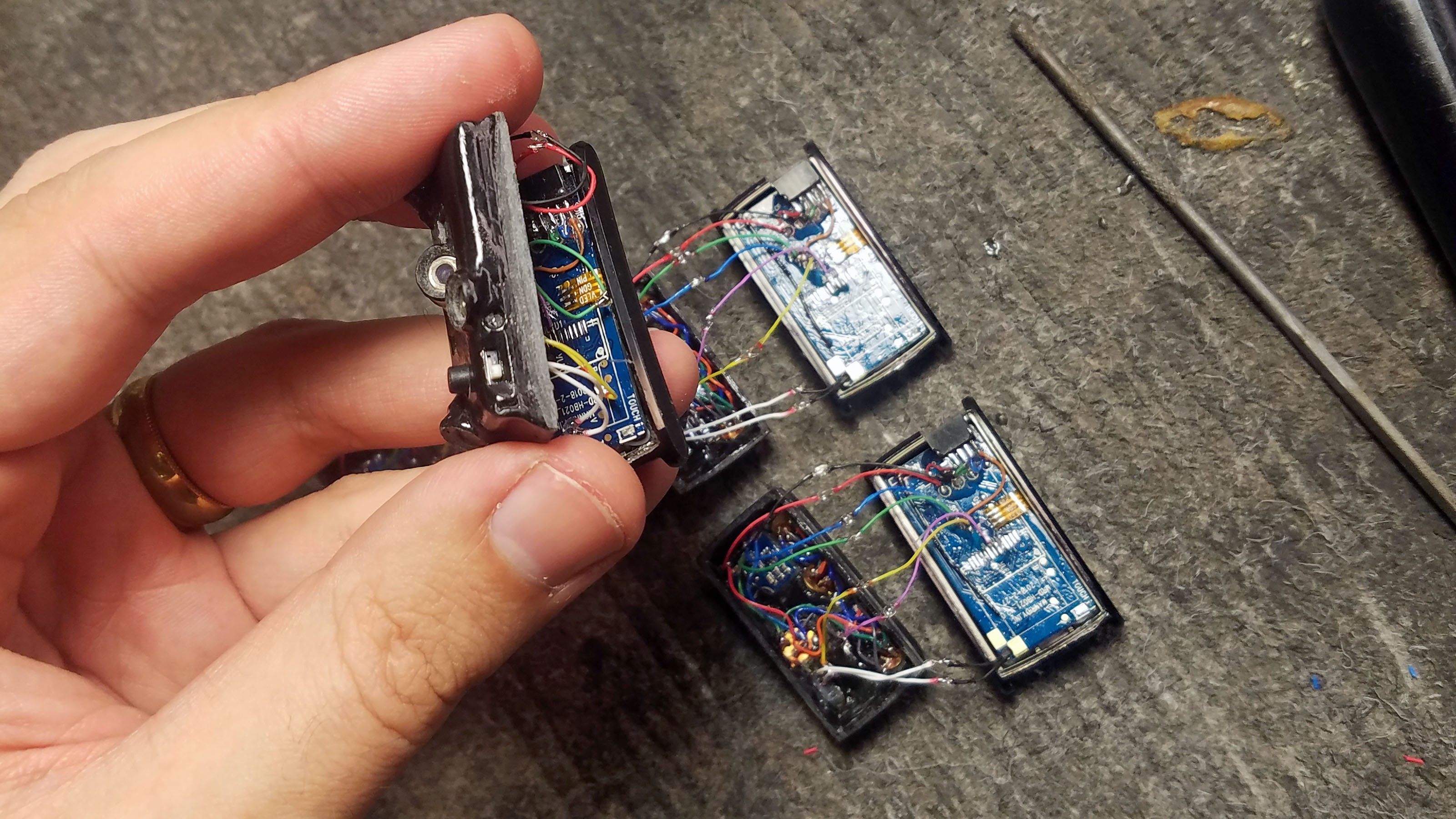
![]()
All four prototypes that are functionally complete.
![]()
The PPG heart rate sensors should fit neatly into the window in the bottom of the enclosure. Double check before permanently closing the device.
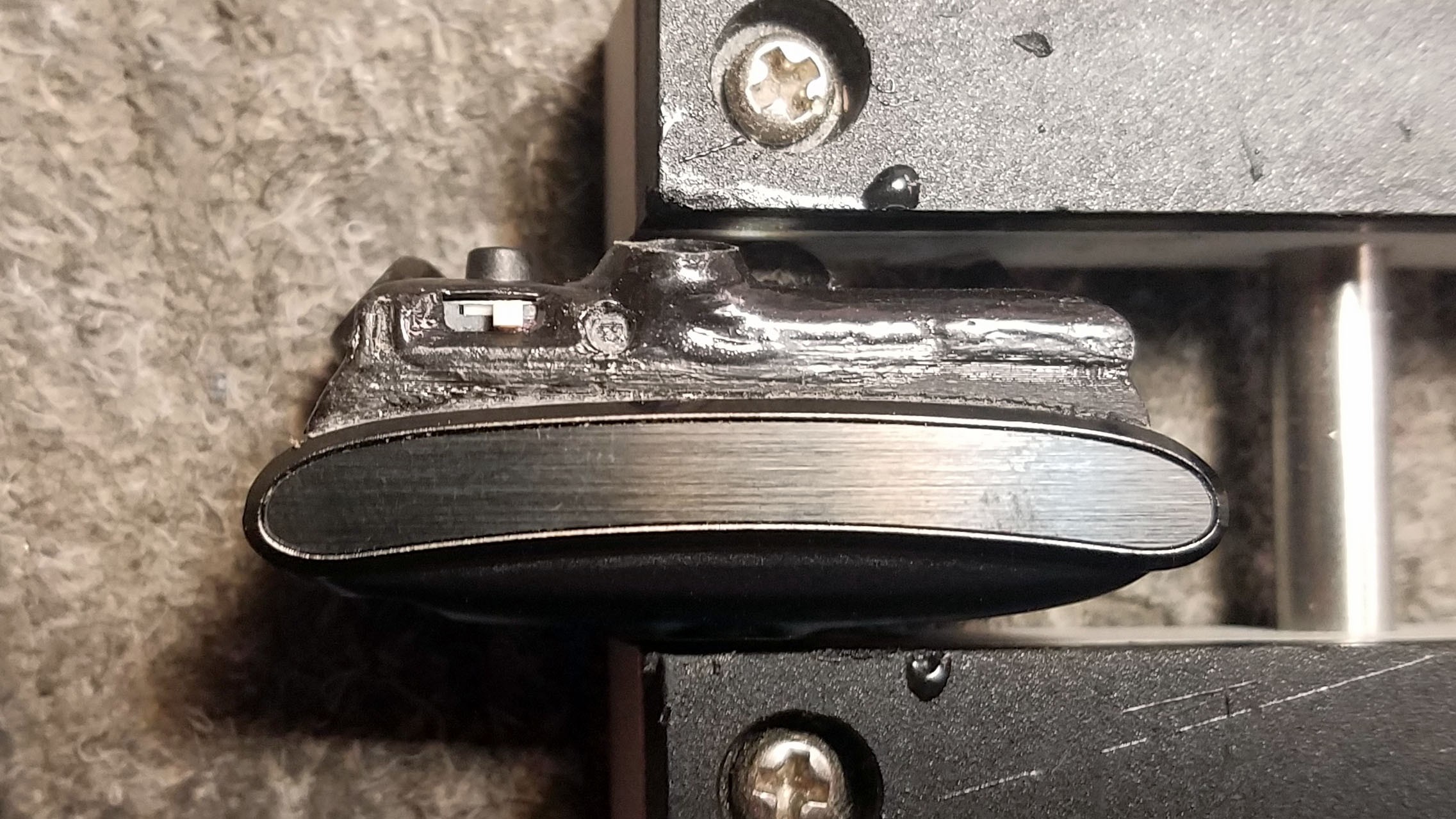
31: Power Switch Detailing With Acetone Plastic Wielding
![]()
The 3D model includes power on/off detailing in relief on either side of the switch. This allows for the addition of colored plastic. No kind of paint will work for this, its plastic wielding or nothing at all.
![]()
Here I have cleaned out the detailing with a tiny screw driver.
![]()
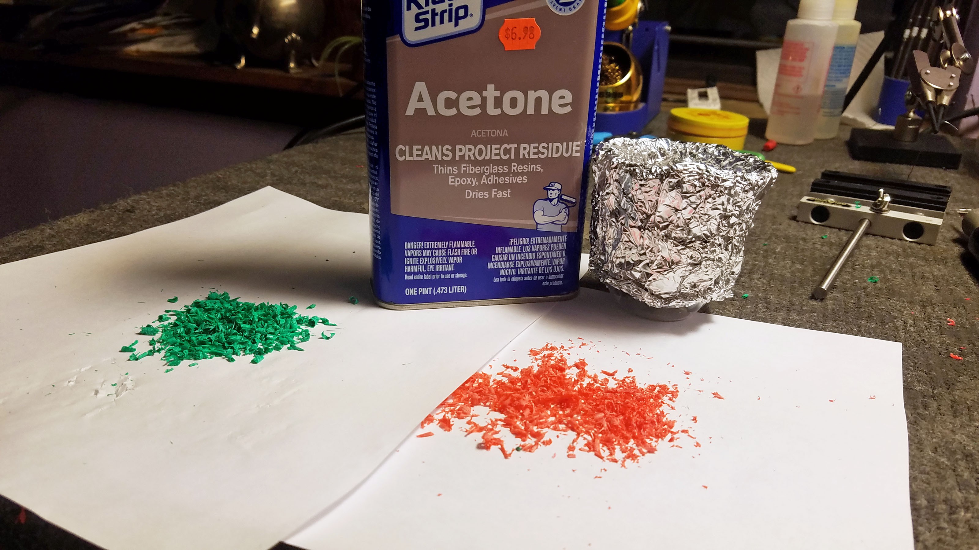
I use green and red ABS plastic shaved from 3D printer filament.
![]()
Green ABS plastic ready to be mixed with acetone.
![]()
I dab a little green plastic/acetone slurry into the sensor cap detailing. The acetone acts as a solvent on the sensor cap ABS plastic, permanently welding the green ABS plastic to the sensor cap's black ABS plastic.
![]()
Red ABS plastic about to be mixed with acetone.
![]()
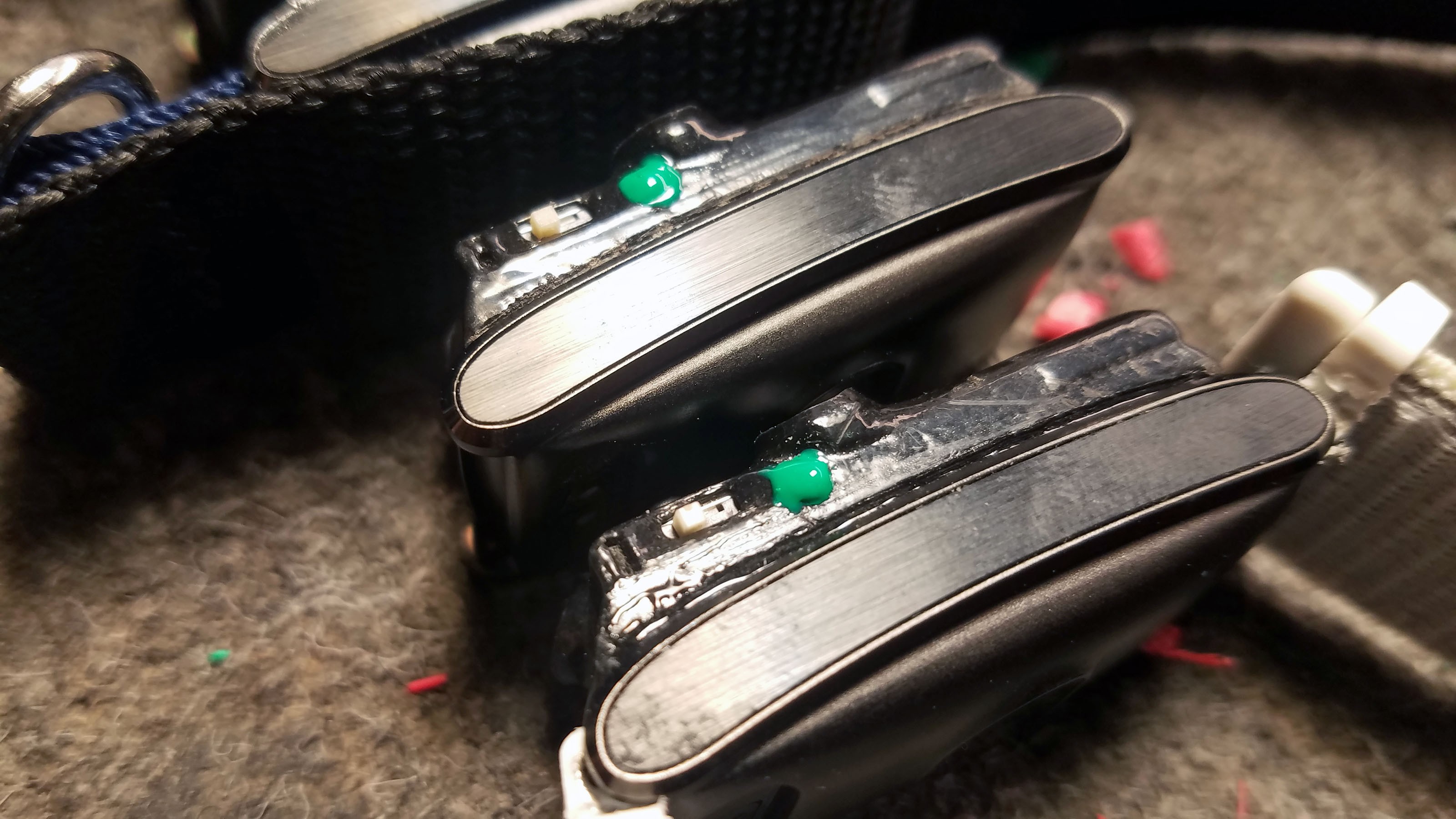
Prototypes with greed and red ABS plastic wielded onto the sensor cap.
![]()
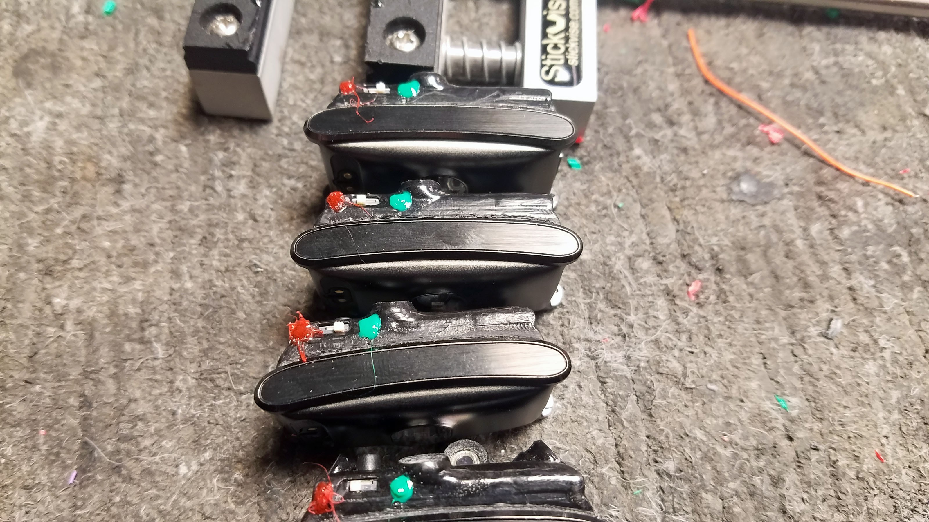
Excess green and red plastic are sliced away, leaving only what fit into the relief detailing - exactly as designed.
![]()
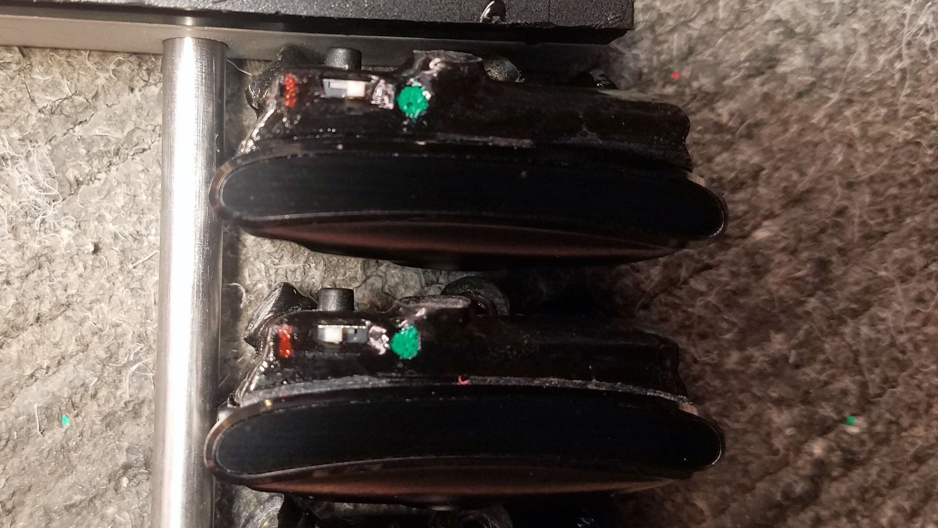
Closeup of power switch detailing. These little touches may seem unnecessary but they make a big difference in how the devices are received.
32: Completed Prototypes
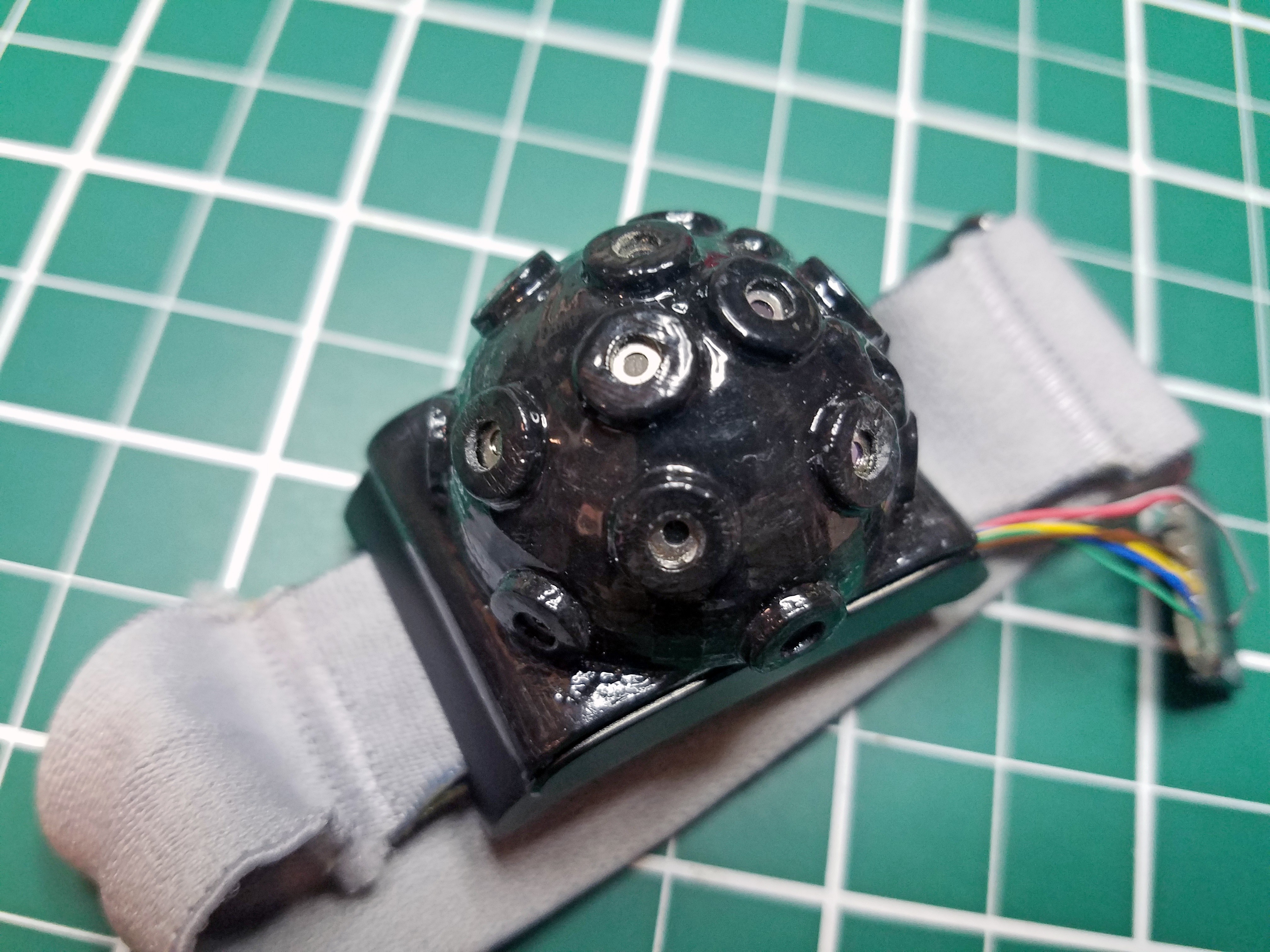
![]()
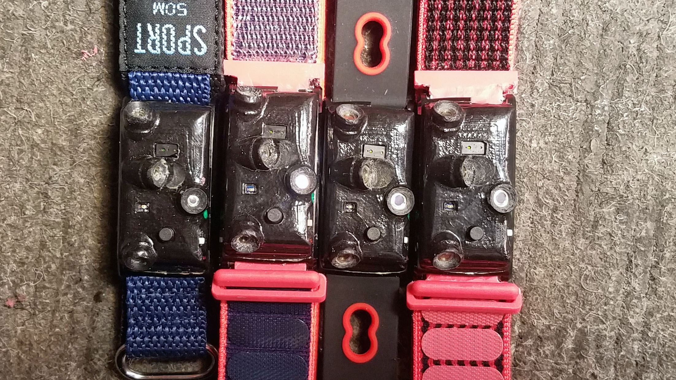
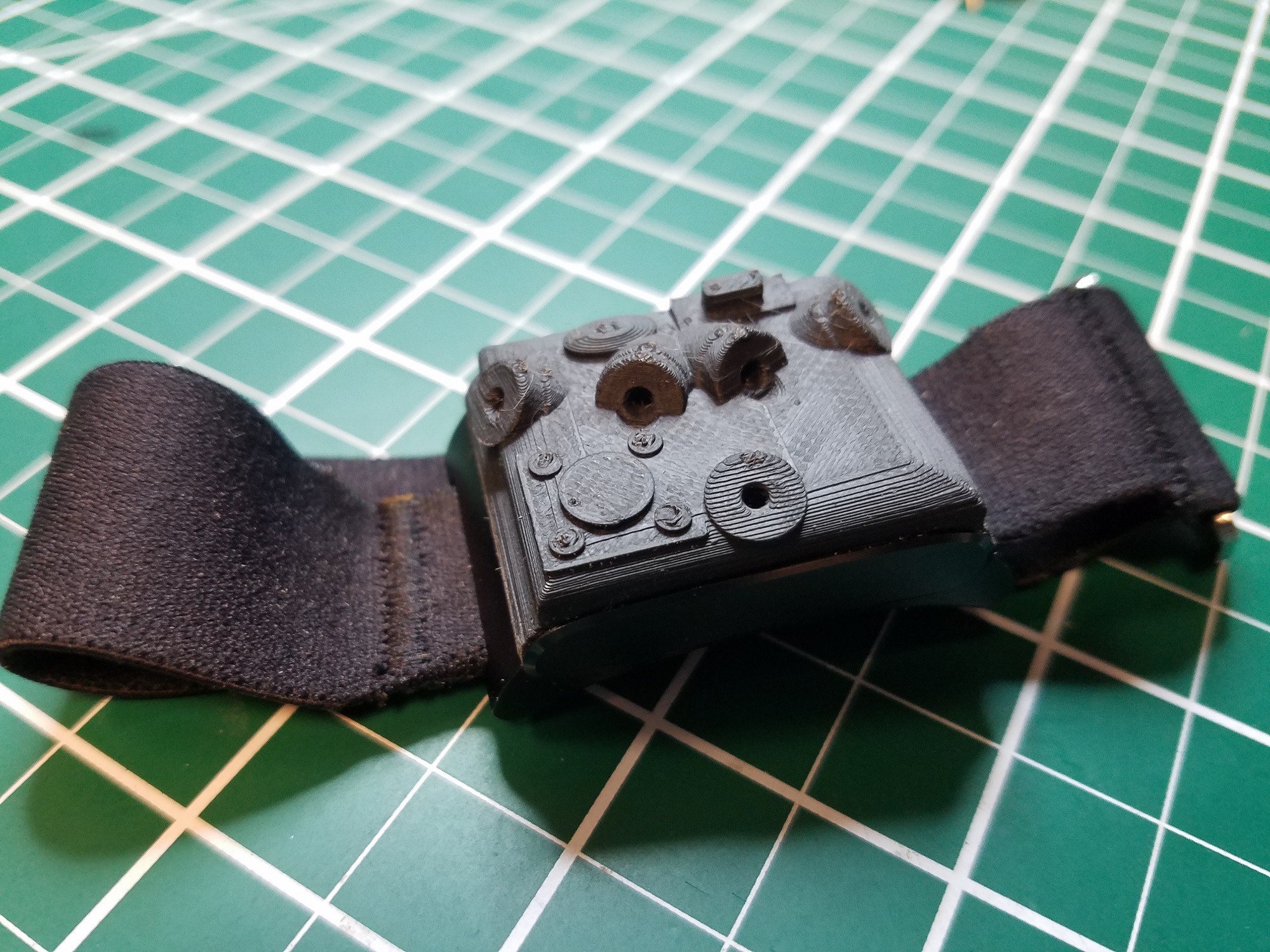
Completed prototypes are attached to a variety of straps. People tend to like having control over there personal appearance so Its nice to give people choices as far as straps are concerned.
![]()
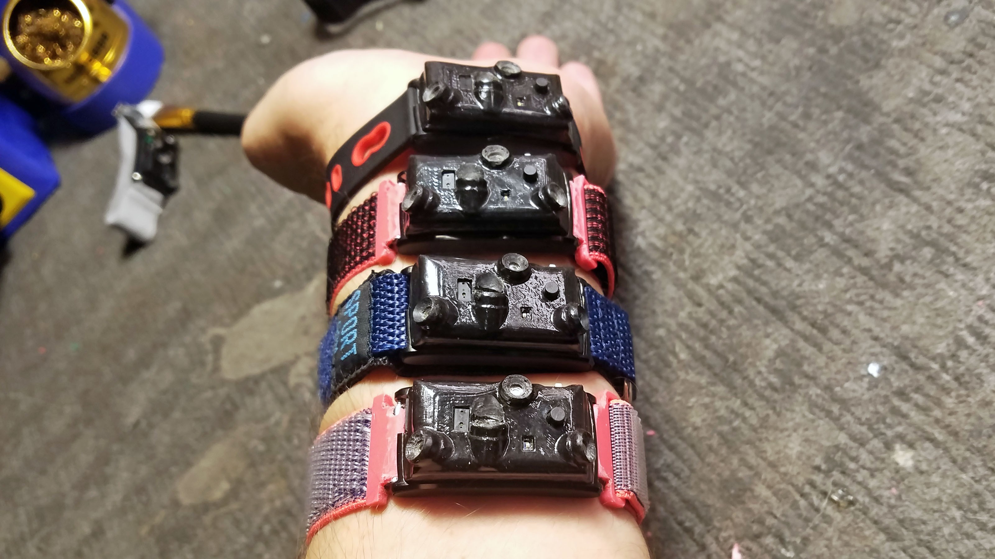
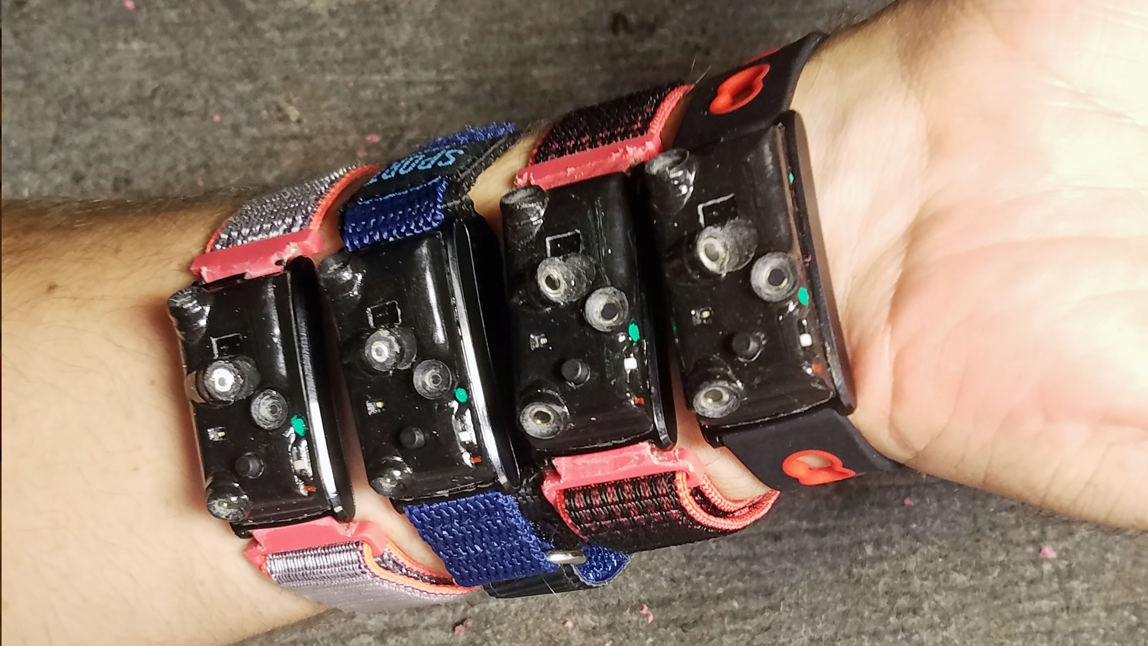
So normally you would only wear one on your wrist... but four looks really cool!
![]()
Ready to be handed off to a test user (after some additional testing).
-
Programming the Tingle
10/19/2018 at 19:06 • 0 commentsAll Tingle related code is stored in this GitHub repository: https://github.com/curtpw/tingle-open
Firmware, Mobile App, Web Interface and MLX90615 Thermal Sensor Programming
The Tingle project consists of four applications:
- Firmware running on the Tingle written in Arduino C for the Nordic nRF5x ArduinoCore (see programming instructions in wearable device hacking section of this project and the platform GitHub repository).
- Hybrid mobile app written in JavaScript using the Cordova hybrid app framework ( link to Android version on Google Play ).
- Web interface written in pure front-end JavaScript. This can run from a simple file server (or GitHub repository as a GitHub page). No server side code necessary ( link to live interface ).
- A small Arduino sketch to program the I2C addresses (2A, 2B, 2C, 2D) of the MLX90615 thermopile sensors.
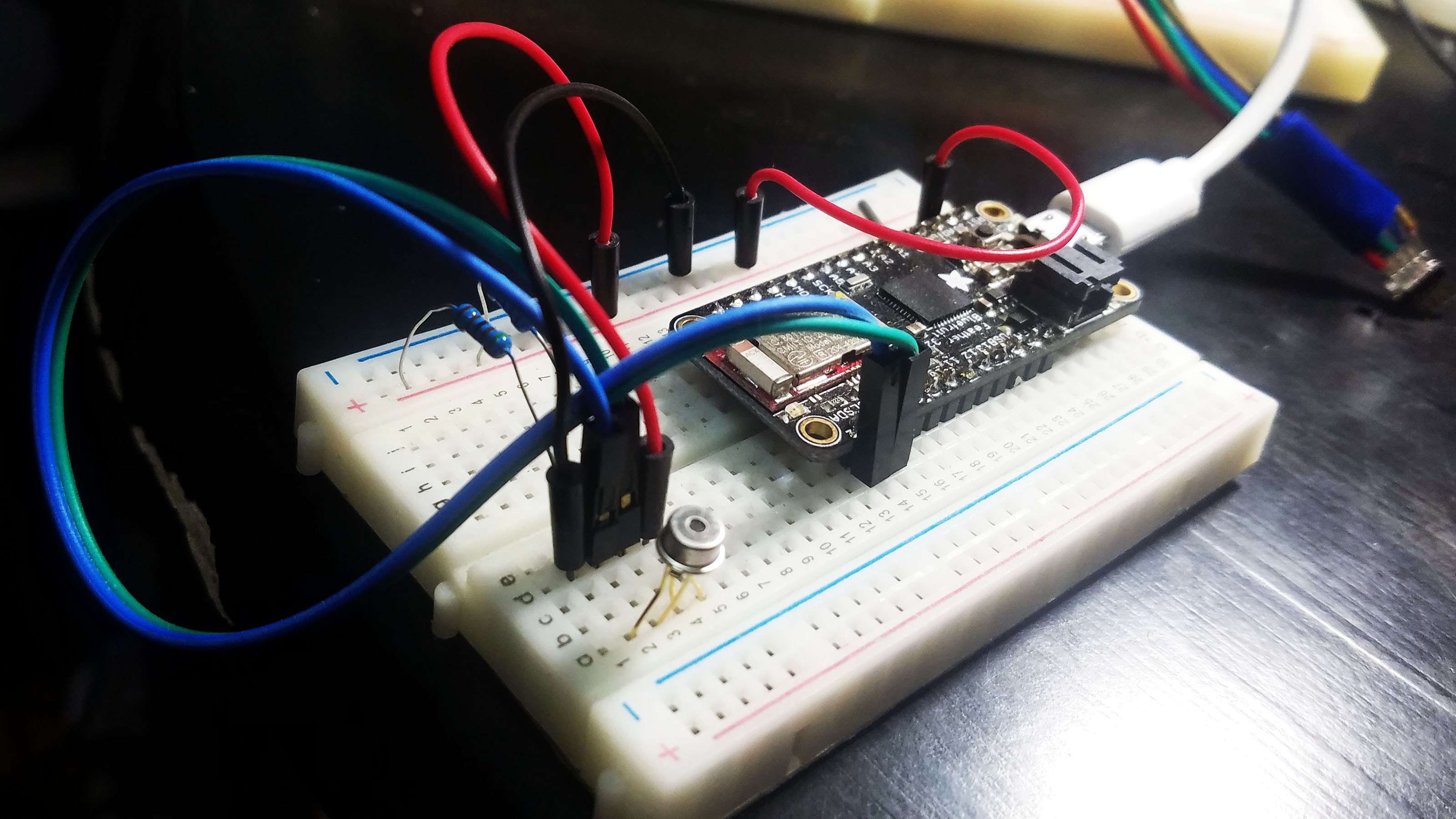
MLX90615 I2C Address Programming Setup
![]()
This is my setup for programming MLX90615 thermal sensors. Any Arduino compatible microcontroller will work as long as it supports I2C (pretty much all of them do).
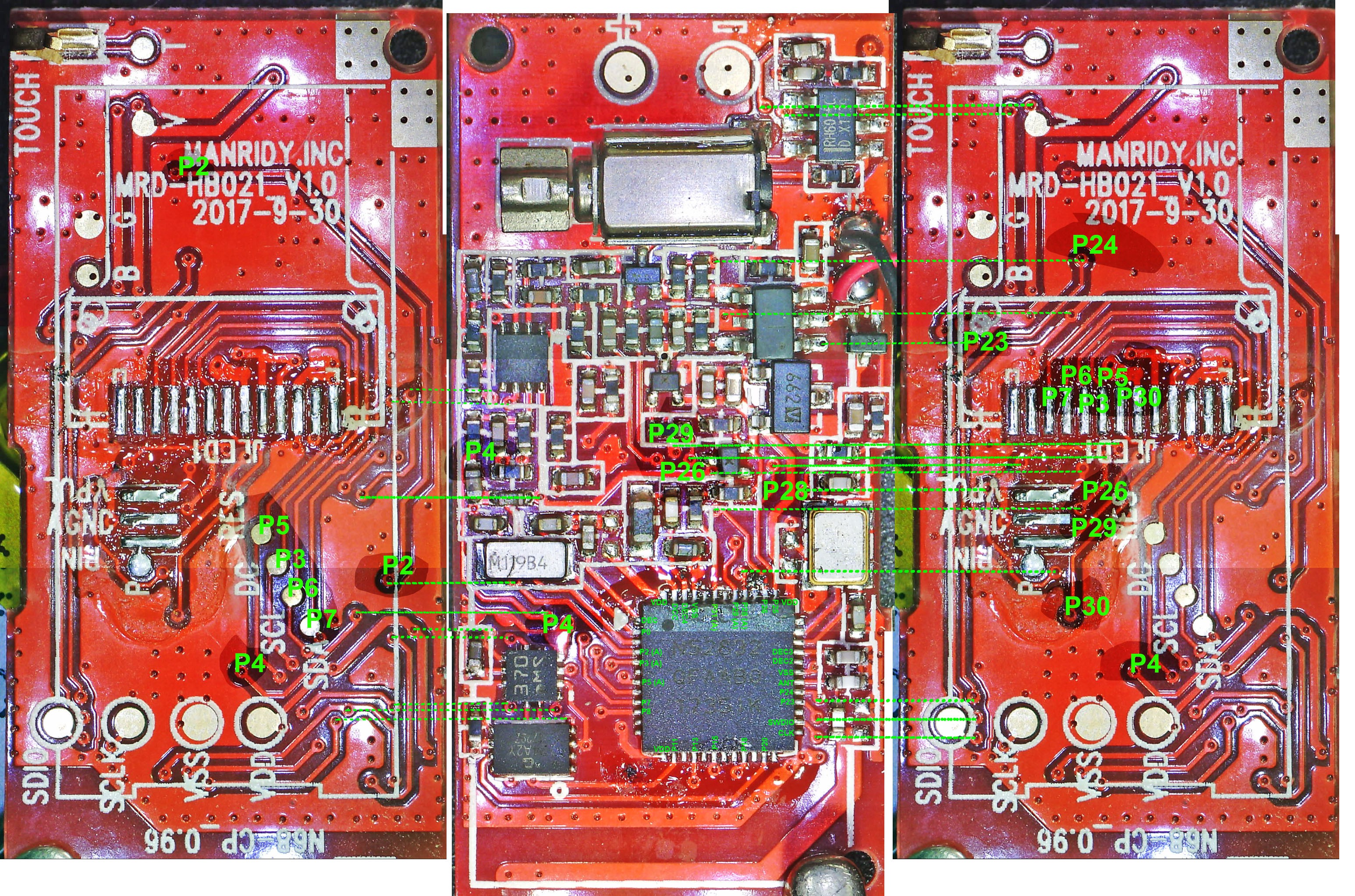
N68 Fitness Tracker PCB Microscope GPIO Diagram
Note: there are both red and blue versions of the N68 PCB. The only difference between them is the presence of a test pad for CS on the OLED display SPI bus. High resolution images available in the GitHub repository.
![]()
-
Wearable Device Prototyping Platform
10/19/2018 at 19:05 • 0 commentsOpen Source
When I think open hardware I think Arduino and Raspberry Pi. When I think open software I think Linux, Python, JavaScript and countless libraries/modules thereof. These are tools and more importantly, community driven platforms. I use hacked fitness trackers to prototype wearable devices because nothing else works - nothing else is small, inexpensive and polished enough. They have become my go-to wearable device prototyping platform for both work and personal projects. This platform has the potential to be a successful community driven open source project - and the Hackaday Prize competition is where I decided to launch it.
I have had a lot of help along the way. Especially members of the smartwatch hacking slack group! Hackaday is a good place to document projects, but GitHub is necessary for a full fledged open source project with multiple contributors. The primary GitHub repository for the "Hacking Wearables for Mental Health and More" Hackaday project is becoming exactly that. I have spent so much time building projects for Hackaday (I decided to build a significant project for each of the 5 challenges!) that I've been a little neglectful of the GitHub repository over the last couple months, but things will get humming again in no time.
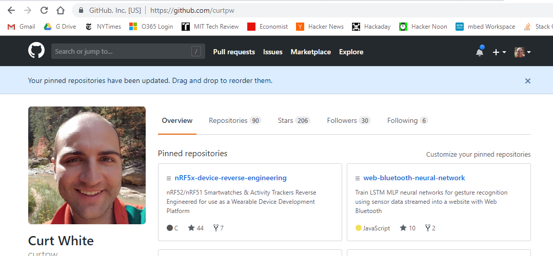
![]()
44 stars and 7 forks is a great start. More of a "fledgling" open source project than a "full fledged" open source project but it is definitely legit, especially considering how niche it is. Personal first. The repositories for various tutorial examples and demonstration projects have gotten some GitHub love as well.
Platform Demonstration Projects
I created three demonstration sub-projects specifically to showcase hacked fitness trackers as a wearable device platform and entered them into the Hackaday Prize: Intraoral Respiration Monitor and Overdose Detector, Stomach Acid Powered Smartpill and EEG Headset. Two of those ended up as finalists despite being created as tutorials for this project. My hope is that the positive reaction these projects have garnered will add additional momentum to making the hacked fitness tracker prototyping platform a successful open source project.
Stomach Acid Powered Smartpill
![]()
Heard of using lemons, potatoes or salt water to create a simple battery? Stomach acid (dilute hydrochloric acid) can be used in the exact same way and is significantly more powerful. I use an array of zinc (anode) and copper strips (cathode) immersed in stomach acid (electrolyte) to turn my stomach into a galvanic cell battery. The stomach battery powers a hacked activity tracker small enough to swallow and reconfigured as a body monitoring 'smart pill'. The user's stomach is the smart pill's battery. By incorporating a $25 hacked activity tracker into existing research I am trying to make stomach acid powered smart pills inexpensive and open source. [LINK TO PROJECT]
(Down camera feed is on an off frame screen so use your imagination when I refer to closeups of the smartpill)
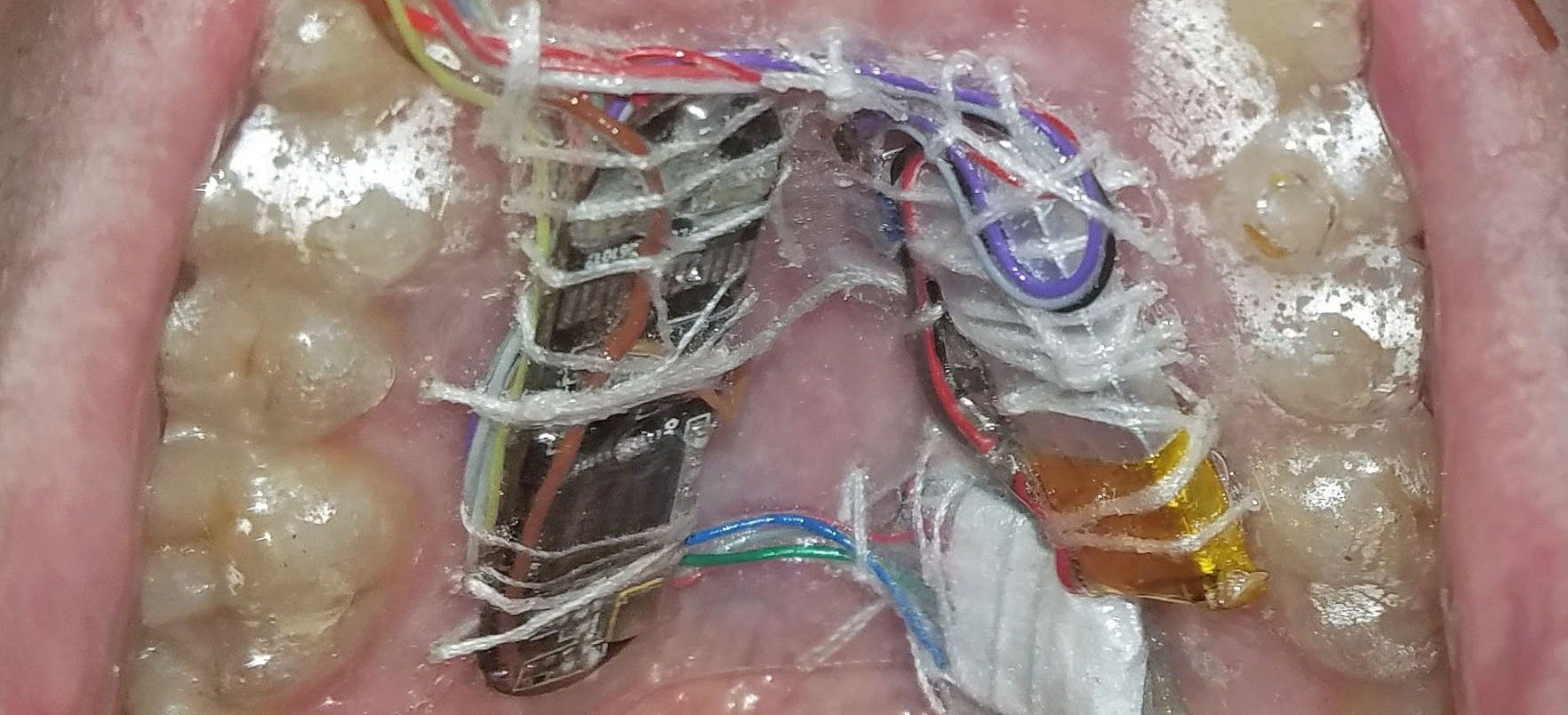
Intraoral Respiration Monitor and Overdose Detector
![]()
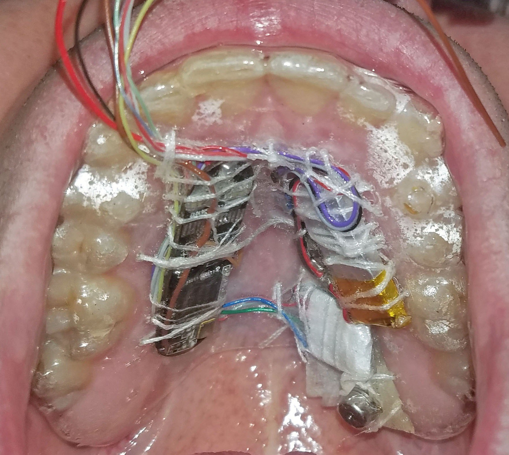
A wireless full waveform respiration monitor worn entirely inside user's mouths (intra-oral) that streams data to a Web Bluetooth enabled web application.
The device measures the air pressure, humidity and skin temperature inside the user's airway. In short, BME280 air pressure sensor + MLX90615 thermopile thermometer + hacked miniature nRF51822 based activity tracker mounted on an ultra-thin custom dental retainer.
My primary goal is to detect opiate overdose. Depressed respiration is the best way to detect overdose and the only approved indicator for the administration of Narcan (Naloxone). Full waveform respiration data is surprisingly difficult to obtain. Spirometers, chest-straps and pulse oximetry (including photoplethysmogram) are relatively inaccurate - particularly when respiration becomes depressed. There are many potential applications and the device could be built using other form factors (bite stick, mouth guard, integration into tracheal intubation. [LINK TO PROJECT]
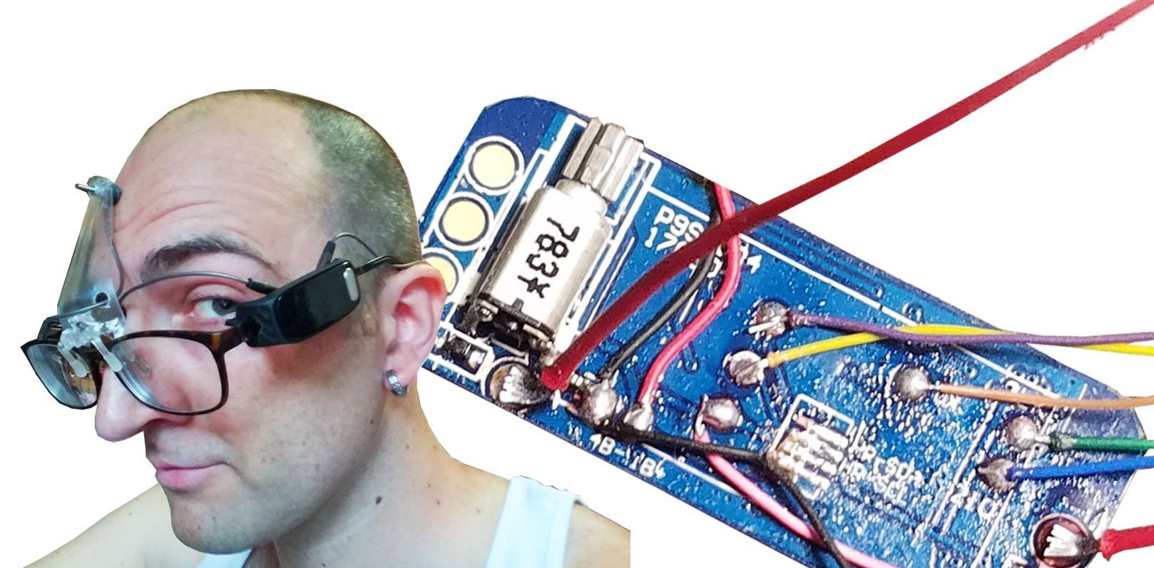
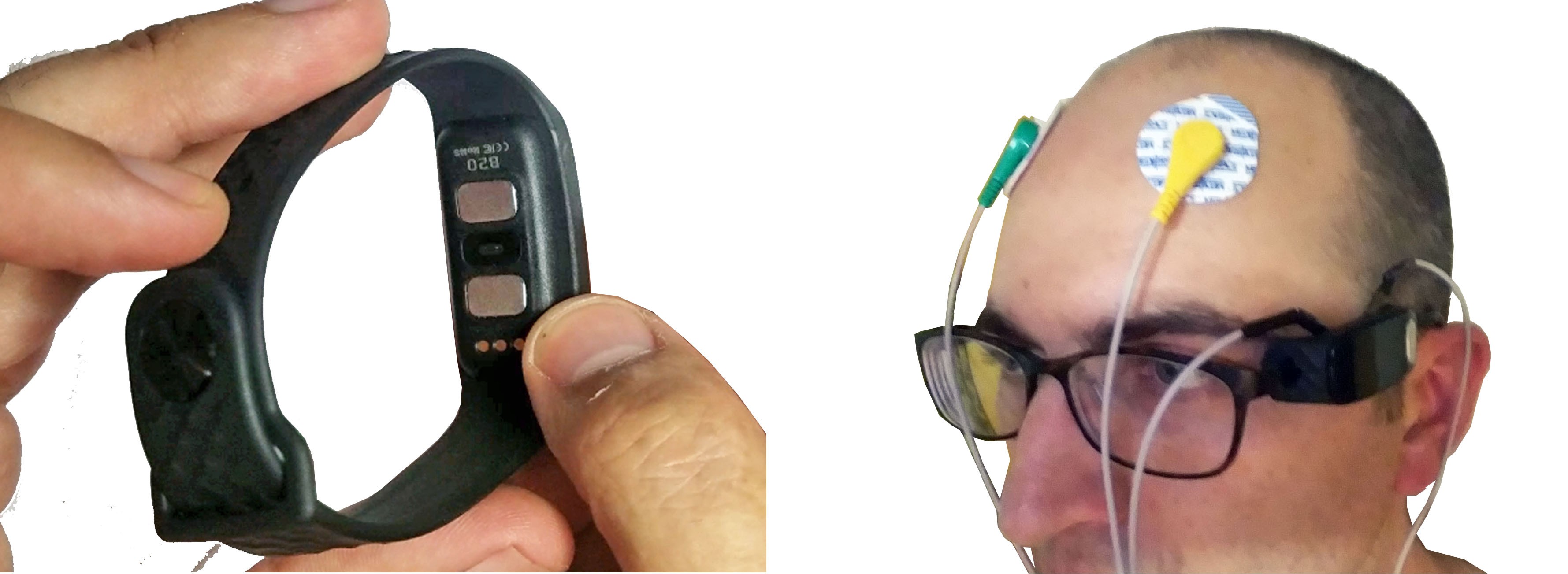
EEG Headset
![]()
The B20 Fitness Tracker contains an ADS1292 bioimpedance sensor which can be used for simple ECG, EMG and EEG sensing. It also contains a nRF52832 ARM Cortex M4 processor which can easily be programmed with Arduino. With Bluetooth, OLED display, accelerometer, optical HR sensor and vibration motor - all for $35 in a miniaturized form factor - it is a pretty extraordinary prototyping platform for simple ECG/EMG/EEG projects.
A few months ago I ran a workshop on hacking the Neurosky/Mattel Mindflex EEG headset. Despite being a super famous hack, the core "concentration" detection feature is still a black box after all these years! I decided to replicate this functionality with the B20. I built some EEG glasses and a Web Bluetooth application which can visualize data from the device and train exportable standalone neural networks for detecting brain states Mindflex style and general human-computer interfacing. [LINK TO PROJECT]
-
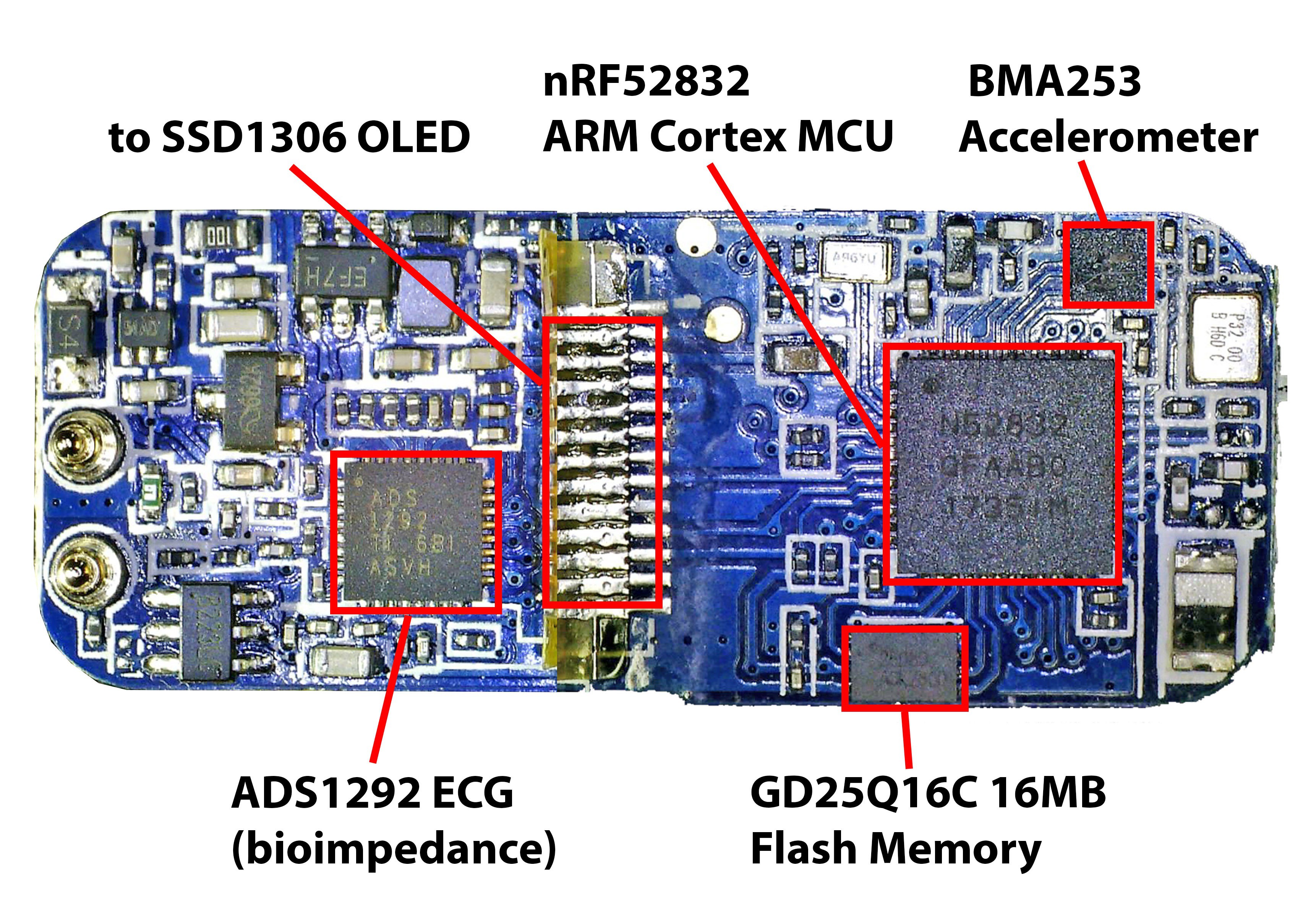
Adding Bioimpedance (ECG, EEG, EMG) to The Platform with ADS1292 ECG Activity Trackers
08/27/2018 at 05:27 • 0 comments![]()
Their are a number of nRF52832 activity trackers which contain the Texas Instruments ADS1292 ECG front-end IC, for example the B20 (links 1 2 3 4 5 6 7 ), the CK12 (links 1 2 3 4 5 ), the G20 (links 1 2 3 4 5 ), and the B9 (links 1 2 3 4 5 ). Although the ADS1292 is marketed for ECG, it is part of a family of chips focused on an array of bioimpedence applications and there is no particular reason it can't be used for simple experimental EEG and EMG projects.
I have provided an in depth tutorial on hacking the B20 activity tracker and applying FIR (Frequency Impulse Response) and FFT (Fast Fourier Transform) analysis to the devices ADS1292 data in this project: https://hackaday.io/project/160618-hacking-a-35-ecg-nrf52-fitness-tracker-into-eeg.
![]()
I have added an Arduino Core variant file to the project GitHub repository for the B20 as well as code examples for EEG with FIR filters, EEG with FFT and ECG with Protocentral's Processing application.
B20 ECG Fitness Tracker Specs:
- Texas Instruments ADS1292 two channel (only one is used) ECG front end
- Nordic nRF52832 ARM Cortex M4 SoC/MCU
- Bosch BMA253 Accelerometer
- Gigadevice GD25Q16C 16MB Flash Memory IC
- PPG Heart Rate Sensor
- 0.95" 64*128 pixel monochrome SD1306 OLED display
- Vibration motor
- 80mAh LiPo battery and battery charger
B20 nRF52832 MCU Pinout
- P19: Button
- P3: Vibration Motor
- P5: SSD1306 OLED Display
- P6: SSD1306 OLED Display
- P7: SSD1306 OLED Display
- P11: GD25Q16C 16MB Gigadevice Flash Memory
- P12: GD25Q16C 16MB Gigadevice Flash Memory
- P13: GD25Q16C 16MB Gigadevice Flash Memory
- P14: GD25Q16C 16MB Gigadevice Flash Memory
- P15: ADS1292 CS
- P16: ADS1292 DIN
- P17: ADS1292 SCK
- P20: ADS1292 START
- P22: ADS1292 RESET
- P23: ADS1292 DOUT
- P25: HR I2C SDA
- P26: HR I2C SCL
- P28: BMA253 Accelerometer CS
- P29: BMA253 Accelerometer SDI
- P30: BMA253 Accelerometer SDO
- P31: BMA253 Accelerometer SCL
-
Text Communication over Bluetooth Serial Example
05/24/2018 at 07:52 • 0 commentsI have created a simple font for the X9 OLED display and used it to demonstrate text communication over serial Bluetooth using my Android phone. The BLE_CHAT example will display input from the Nordic phone app on the X9 display. If "red", "blue", "green", "yellow", or "purple" is sent, the message will be displayed in the corresponding color and a custom reply will be sent from the X9 activity tracker to the phone app.
I have also included a simple sketch demonstrating the super simple font.
All files for examples can be found in the GitHub repository, including required libraries and application hex files which I compiled myself. If you have a hacked X9 you can immediately load my compiled application to quickly check out the demo. I am adding the actual example sketches to the hackaday.io project files as well.
GitHub repository file directory:
nRF5x-device-reverse-engineering --> X9-nrf52832-activity-tracker --> Firmware --> examples --> nrf52_X9Project_BLE_CHAT
nRF5x-device-reverse-engineering --> X9-nrf52832-activity-tracker --> Firmware --> examples --> nrf52_X9Project_ALPHABETNordic UART Bluetooth Serial app: https://play.google.com/store/apps/details?id=com.nordicsemi.nrfUARTv2
-
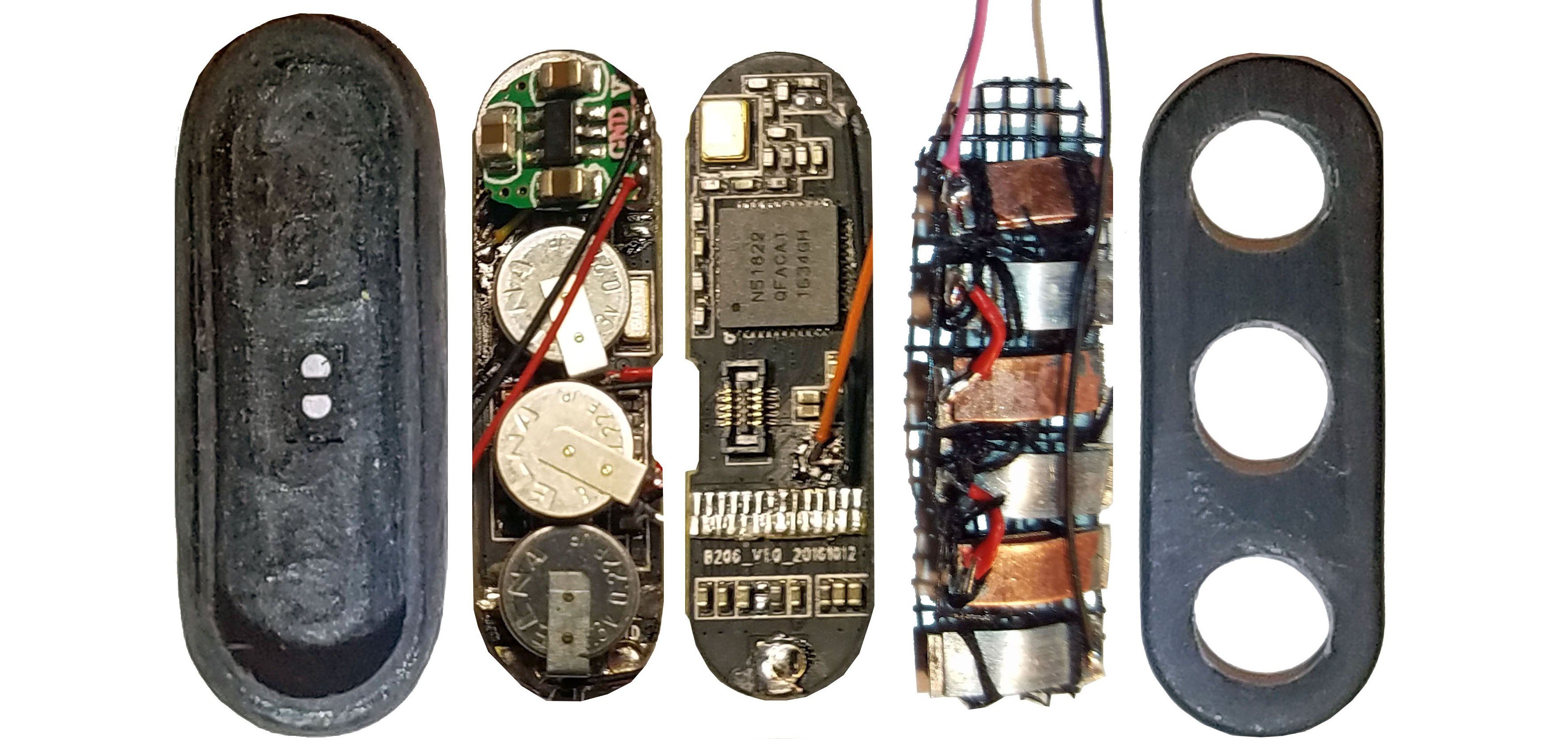
Intraoral Respiration Monitor - A Computer Inside Your Mouth!
04/23/2018 at 19:06 • 0 comments![]()
A wireless full waveform respiration monitor worn entirely inside user's mouth (intra-oral) that streams data to a Web Bluetooth enabled web application. We built this by hacking the tiniest ARM based activity tracker we could find!
The device measures the air pressure, humidity and skin temperature inside the user's airway. In short, BME280 air pressure sensor + MLX90615 thermopile thermometer + hacked miniature nRF51822 based activity tracker mounted on an ultra-thin custom dental retainer.
We also spun this off into a separate Hackaday project with more detail, check it out.
-
The "Tingle" Gesture Recognition and Biofeedback Device For Compulsive Behaviors
04/20/2018 at 03:31 • 0 commentsThe "Tingle" Gesture Recognition and Biofeedback Device is a project I'm working on at the Child Mind Institute. To put it very bluntly, it is designed to help kids stop compulsively tearing out their hair, a disorder called trichotillomania which is surprisingly prevalent. I built the prototype using the X9 activity tracker presented in this project.
![]()
From the MATTER Lab website:
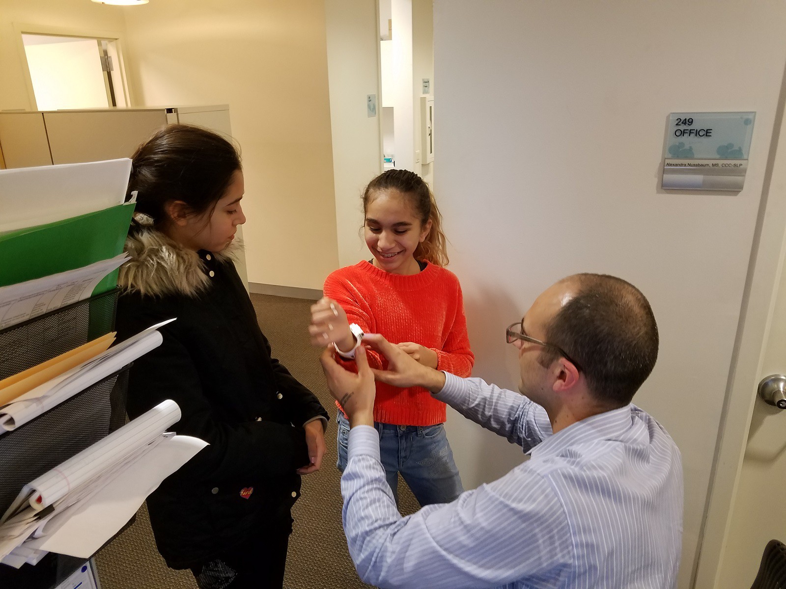
As you are about to compulsively pull out your hair, bite your nails, or engage in some other body-focused repetitive behavior, you feel a tingle on your wrist. Then a notification is sent to an online dashboard. This information helps you to be mindful of your behavior as part of a behavior modification therapy, and helps your therapist monitor your progress. This is the rationale behind building the Tingle and applying for a patent. We have just run a pilot study and are preparing for a clinical trial.
Prevalence of body-focused repetitive behaviors (BFRBs)
Body-focused repetitive behaviors (BFRBs), symptoms of Obsessive Compulsive Disorder (OCD) and other conditions involving compulsions (e.g., Autism Spectrum Disorder) involve compulsively causing physical injury and/or damaging one’s physical appearance. These are among the most poorly understood symptoms; they are often misdiagnosed and undertreated. BFRBs include hitting oneself, biting, pulling out hair, skin picking and cutting, as well less severe but damaging behaviors such as nail biting, thumb sucking, and nose picking (Families & Health). These symptoms affect at least 5% of the population (Families & Health); hair pulling alone affects 1%, or about 3 million people in the US (Diefenbach, Reitman & Williamson 2002). BRFBs are highly comorbid. Studies have shown that as many as 70% of those with one BRFB will have another co-occurring BRFB (Conelea, Frank & Walther, 2017). While often impairing, affecting medical health and/or disfiguring, these symptoms are frequently reported but often not observed in clinical settings. This makes diagnosis, as well as treatment planning and monitoring, exceedingly difficult. To avoid pain and disfigurement, it is imperative to identify a reliable means to automatically identify and monitor BFRBs, especially outside the clinic setting. Clinicians need data on BFRB frequency and timing for the purposes of diagnosis, treatment planning and monitoring while patients need immediate, real-time feedback to make behavioral therapies more effective.
The “Tingle” device
To address this previously unmet clinical need, we have created a prototype for a wrist-worn device called the “Tingle” that can monitor and record BFRBs while also providing real-time (haptic) feedback (on the wrist) to the individual with BFRBs when they occur. The Tingle is the subject of U.S. Patent Application #15/816,706 filed January 26, 2018.
Testing the accuracy of the Tingle device for detecting different simulated BRFBs.
In a pilot study to establish the accuracy with which the Tingle can detect BFRBs in a controlled setting, we recruited 50 healthy, adult volunteers to wear the Tingle and repeatedly simulate 9 different behaviors (eating, smoking, thumb sucking, nail biting, nose picking, skin picking, and hair pulling from three locations). We just gathered the data and are analyzing the data now!
Testing the clinical efficacy of feedback via the Tingle in therapy.
This proof of concept leads to the critical next step of applying the Tingle to the clinical setting in which we will confirm the Tingle’s effectiveness in preparation for an FDA New Device Application and plan for commercialization. This will open the way for broad distribution in clinical practice as a diagnostic tool and to support the evaluation and implementation of pharmacological and behavior therapies for BFRBs.
Conclusion
The Tingle is well-positioned to address the tremendous unmet need in the care of individuals with BFRBs and other damaging and impairing compulsive behaviors. The Tingle will revolutionize the diagnosis and treatment of at least 5% of the population affected by these severe symptoms by using a convenient, automated, unobtrusive, and inexpensive device that both records behaviors for clinical assessment and provides accurate, real-time feedback to the wearer in support of therapy. We will evaluate the Tingle wearable device to facilitate diagnosis and therapy outside the clinic. In turn, this will facilitate the more rapid commercialization of this product to make it more widely available to clinicians and their patients.
References
- Conelea, Frank & Walther, 2017
- Diefenbach GJ1, Mouton-Odum S, Stanley MA. (2002). Affective correlates of trichotillomania. Behaviour Research and Therapy, 40(11). 2002 Nov;40(11):1305-15. doi:10.1016/S0005-7967(02)00006-2
- Families & Health Archived March 28, 2009, at the Wayback Machine., American Association for Marriage and Family Therapy [http://www.aamft.org:80/families/Consumer_Updates/Body-focusedRepetitiveDisorders.asp]
![]()
![]()
-
Get More GPIO The Easy Way
04/20/2018 at 00:28 • 0 commentsIf I couldn't add additional sensors to the X9 Activity Tracker it would be useless to me. To be perfectly honest, I don't even particularly like activity trackers. Unlike an Arduino, Teensy, ESP32 or ARM Cortex breakout board, hacked activity trackers don't provide convenient access to additional MCU GPIO for adding sensors etc. There is a simple solution: cannibalize GPIO from existing components. I always remove the OLED for my own projects. I'd rather interact with devices using a mobile app or web application over Bluetooth. Bluetooth is the whole reason I find Nordic chips so appealing. Take a look at the below example of how I desolder the X9's OLED display to gain additional GPIO for sensors:
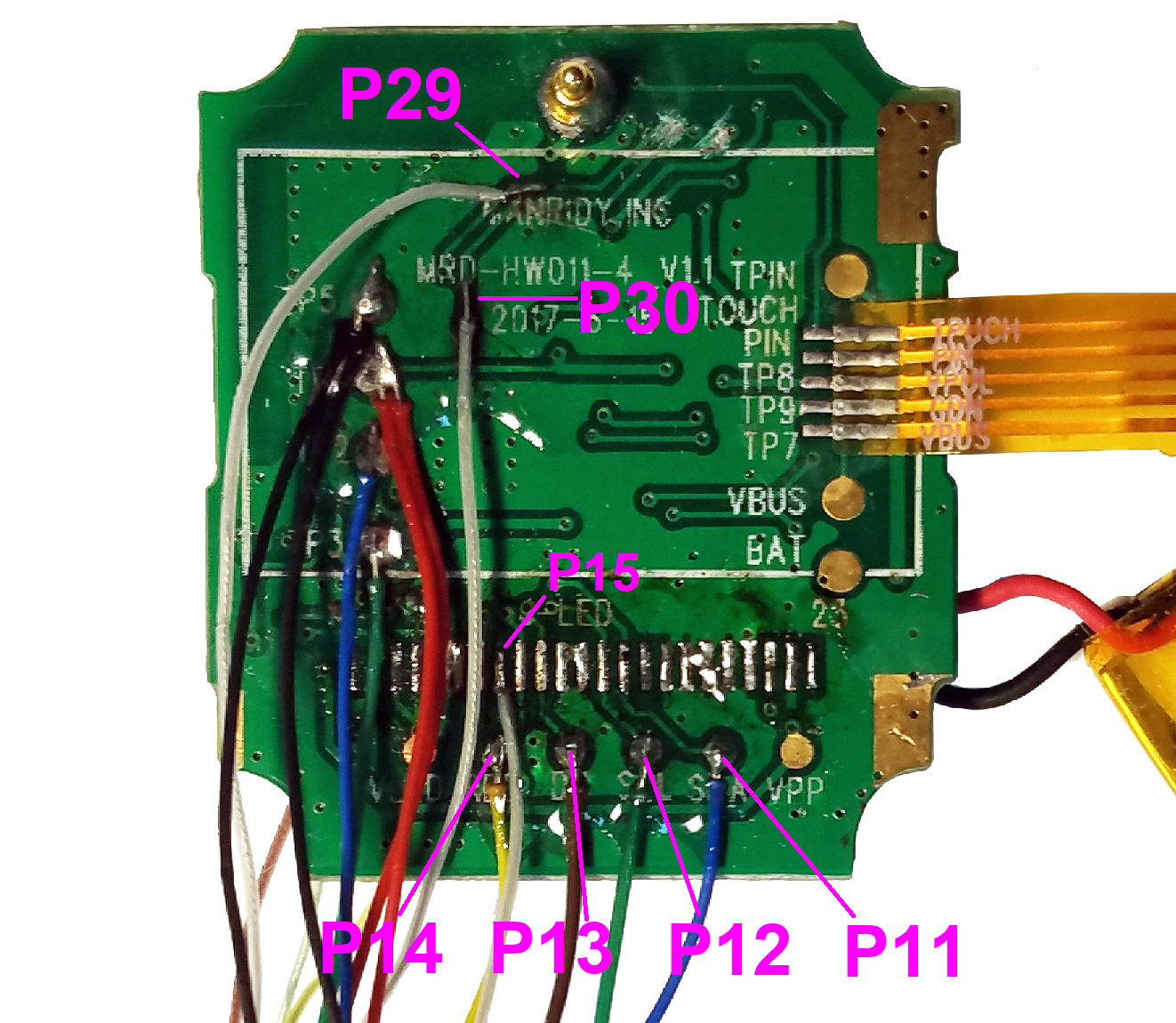
![]()
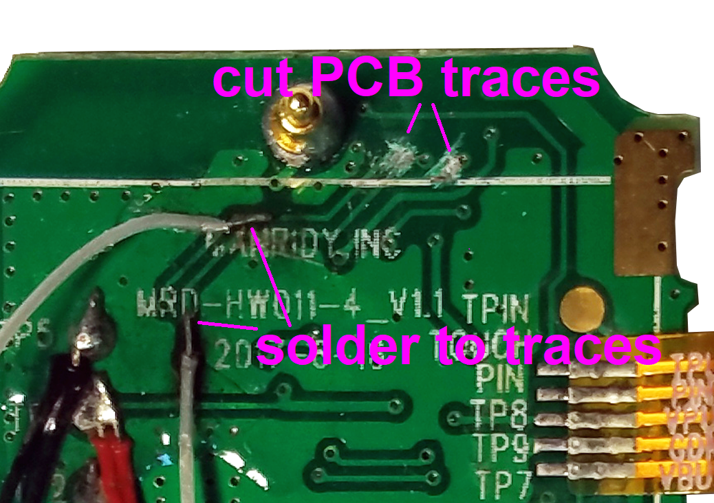
The primary OLED GPIO (P14, P13, P12, P11) are really easy to access because there are nice big test pads to solder underneath the OLED ribbon cable. P15 is a little bit harder because you have to solder the place where the ribbon connected, but still no biggy. But what if you need more GPIO or want to keep the OLED? You can access P29 (heart rate detector photosensor) and P30 (touch sensor) by scraping off the solder mask from the appropriate traces and directly soldering a wire to the trace. You will want to isolate your connection to the MCU from supporting circuitry related to the original use of those GPIO. In order to do this, solder to the trace in a place where there is nothing connected between your solder point and the MCU (nRF52832), then cut the trace above your solder point.
![]()
You can use this annotated, highly detailed composite microscope image of the X9 PCB (high resolution version in project files) and list of component pin connections to figure out traces you might want to solder into:
![]()
- HR_LED_PIN 4
- HR_DETECTOR 29
- TOUCH_BUTTON 30
- VIBRATE_PIN 8
- BATTERY_PIN 28
- OLED_CS 15
- OLED_RES 14
- OLED_DC 13
- OLED_SCL 12
- OLED_SDA 11
- OLED_LED_POW 16
- OLED_IC_POW 17
- KX126_CS 24
- KX126_SDI 19
- KX126_SDO 20
- KX126_SCL 18
- KX126_INT 23
- FLASH_CS 22
- FLASH_SDI 19
- FLASH_SDO 20
- FLASH_SCL 18
-
"Thermo" Position Tracking Wearable Device
04/19/2018 at 23:29 • 0 commentsThe "Thermo" position tracking device is a controller for VR/AR or any other situation where tracking a user's hand in 3D coordinate space might be useful. The Oculus Rift and HTC Vive virtual reality headsets both have 6DoF (Six degrees of freedom) position tracking controllers. They also depend on a camera or some other external device to achieve 6DoF hand position tracking. At the Child Mind Institute MATTER Lab we applied machine learning techniques to vast amounts of thermal imaging data and leveraged the results using a device worn on the wrist with a fairly sparse sensor configuration. We are attempting to achieve the capabilities of the Oculus and Vive controllers without any external reference point. This device was prototyped using the X9 Pro activity tracker - the exact activity tracker presented in this project.
![]()
![]()
Hacking Wearables for Mental Health and More
Presenting the "Tingle" wearable for compulsive behaviors and a hacked fitness tracker wearable device prototyping platform.


 The electronics have been removed from the enclosure. The battery and heart rate (HR) sensor are lightly glued to the bottom of the enclosure but can easily be lifted out with a small prying tool.
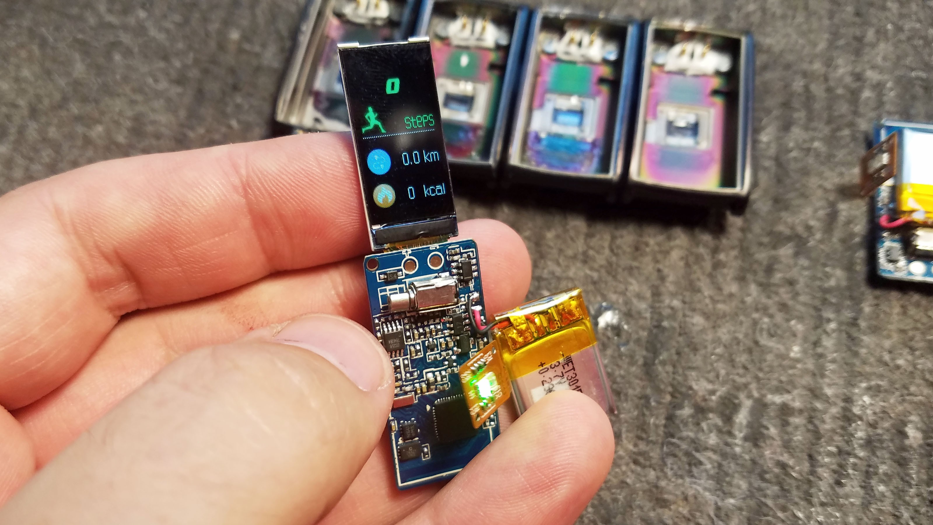


 This is a little tricky because the button will have a lot of force applied to it which means it has to be really firmly attached to the cap - but the button is also really easy to clog with epoxy. I usually epoxy the button to the enclosure in two stages: first with a small amount of fresh epoxy and second with a larger amount of epoxy that has hardened to the point of being a little sludgy.