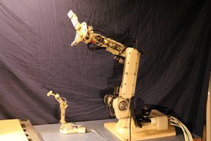
The OWI-535 Robot arm is actually an excellent bit of engineering. Made of thin-walled injection molded plastic and a handful of small DC motors, it is very inexpensive, yet is a fully functional robot arm.
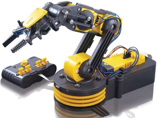
It has three main drawbacks:
- It is a little bit underpowered
- It is a little bit delicate in construction
- It does not have a closed-loop control system (other than the controlling human’s sight and judgement)
The first two can be compensated for to some extent with replacement of power supply and motor management, and a small amount of reinforcement (the latter is not completely necessary, if the application is tolerant of a bit of flexure, lack of rigidity can actually be a benefit).
The third drawback can be solved by adding a control system: sensors to detect arm joint position, motor controllers to trigger the motors, and a microcontroller.
OWI makes their own USB control system which has a microcontroller and motor controller chips, but the actual “controller” is still just the human, pressing the buttons on their PC application - the closed loop sensing is the human. Any obstructions or interruptions in motion are not detected electronically. Also, since the ultimate controller is still the human, now just moved in front of the computer screen, the wired hand-held control panel is discarded, in favor of the on-screen controls.
I felt that the system could be very useful, if it was closed-loop and was able to be integrated into a coordinated computer system that used conditional logic instead of just manual human control.
I have seen other implementations, some very skillful, that have used added potentiometers, or optical encoders. Initially I considered adding potentiometers. They were preferable to me over a pulsing optical encoder because they give a sense of the absolute position without a homing procedure. Additionally, they would be tied to the actual arm position, and not the position of an internal gear that was abstracted a few levels from the actual arm position by backlash.
Ultimately I did not find any potentiometers that were suitable for what I desired. They all required bulky external mounting, or mounting that was not exactly repeatable. I was building many of these, so I did not want a one-off hot glue type installation. I wanted the same code to run on all robots, without unique compensatory constants for every single robot. Additionally, I found that the potentiometer mountings introduced another level of backlash that I wanted to avoid.
I arrived at a solution, a custom-made integrated variable resistor contained in each joint. Invisible and elegant, they did not impose any rotational restrictions or increase the device’s physical envelope.
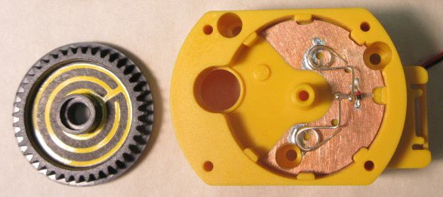
An L9110H motor controller chip addresses each motor. The original manual control box is now wired through the microcontroller (its use is entirely optional). That allows you to drive the robot to certain positions with a very nice, physical, responsive interface, and then hit the physical “teach” button to have the microcontroller learn the position. Once learned, these positions can be run in complex sequences, in coordination with other robots.
More to come in the logs...
 Kenji Larsen


 Xavi Cano
 Mateo Estigarribia
 Michael Laffin
Hi Kenji, great hacking! I am not sure if you are aware of it but another guy accomplished the feedback optically which should be much more robust and repeatable. Here is the link (if you don't know it already, since I believe it was featured in hackaday):
http://www.instructables.com/id/Modifications-to-Robot-Arm-for-Opto-Coupler-Feedba/?ALLSTEPS