After the theory, let's practice :-)
I simply wired the simple gate as designed yesterday and it runs smoothly:
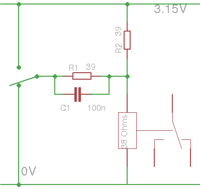
So I can hear the characteristic click of the relay, with a sound that differs from the switche's.
But I don't learn anything...
Or did I ?
It works well at 3.15V then ceases after a few minutes.
3.30V, OK.
Then now it's 3.40V...
The coil is constantly energised and power is dissipated in the copper coil, which changes resistance. This increases the working voltage... Fortunately, I'll use adjustable POL regulators :-)
So before examining the dynamic behaviour, let's make sure the thermal behaviour is good.
Let's say that 3.5V is a good compromise.
With the pulse generator, I'm able to drive one relay coil with a lozange waveform. In turn, this drives the slave coil (#1) with the 3.5V square waveform.
The master coil behaves well and I could push the pair to more than 25Hz. However the waveform at the coil of the slave is quite dirty, with and without the parallel 100n capacitor. I don't see overshoot but a lot of bouncing...
Pushing to 50Hz with a triangle waveform, the master still works well but the output is very bouncy. This sort of relay can switch very fast but the outputs will become very dirty in comparison. Capacitors have no apparent influence on the waveforms so let's just get rid of them.
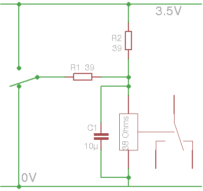
A 4.7µF tantalum across the slave's coil smoothes the waveform enough to become quite recognizable. No need of a parallel capacitor with the liaison resistor. The 4.7µF reduces the junk on the coil (a little bit), not the actual bounces, so the EM emissions are still be quite high. 10µF would be better but 47µF is too much.
Below: coil voltage without cap : (1V/div, 1ms/div, lower trace is the control voltage of the master relay, with 1/2ms chopped by the trigger at 0.5V)
Below, with 4.7µF tantalum:
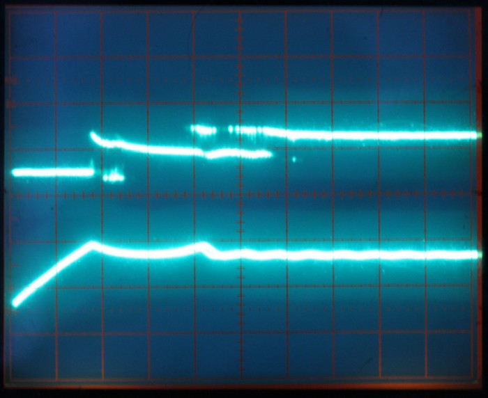
When pushed to 50Hs, the cycle time is 20ms, with 10ms high and 10ms low. The coil voltage looks like that:
Compare to the unfiltered signal (no capacitor, and the lower trace is the clean 50Hz ramped signal from my generator):
The transients last 4ms (2ms/div).
The thermal drift does not exceed 3.5V too much so that's reassuring.But the protoboard's bad contacts make the circuit very unstable, I must solder it...Now, considering that the relays will draw 50mA (in average) and there will be at least 30 per bit-slice module, the expected power consumption of the bitslice is around 1.5A ! Let's round it up to 2A.
For 8 bits, that's 16A.
For 16 bits, 32A at 3.5V, or approximately 100W, and there is still no control or memory circuit !
It is obvious that half of the relays of the bitslice (16 at least) are MUX relays that are completely controlled by the outside circuits, all in parallel. They will be wired in series to reduce the power losses, and they will not use PBRL, but swing between 20 and 60mA.
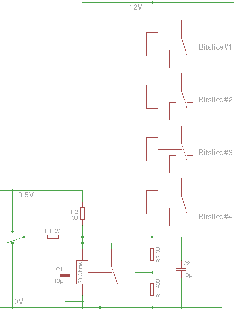
(the resistor values are NOT experimentally checked yet...)
Furthermore, there are several multi-level MUX and DEMUX but only one path is taken so there are cases where one first-order MUX (controlled by bit0) provides useless data. These MUX can be left at rest.
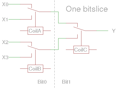
The above diagram shows that at most 2 relays need to be energised. This is solved by the circuit below:
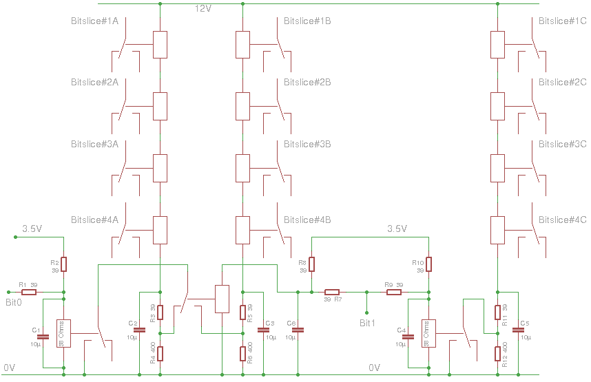
Bt1 controls which branch gets more current, with the help of a 3rd relay that MUXes either of the first levels signals.
And now that I think about the bounces, I realise that the latch won't work well... The capacitor will receive a lot of noise, unless it's a very high capacity (>100µF) with a series resistance.
A two-stage relay latch, with correctly spaced pulses (with a 10ms interval between them), is necessary. The test at 50Hz shows that 10ms pulses are possible but the control signal must be clean...
20161107: The above assertion must be carefully examined. A single clock source is better than a sequence... The new project #ReTest-RPi will clarify this.
 Yann Guidon / YGDES


Discussions
Become a Hackaday.io Member
Create an account to leave a comment. Already have an account? Log In.