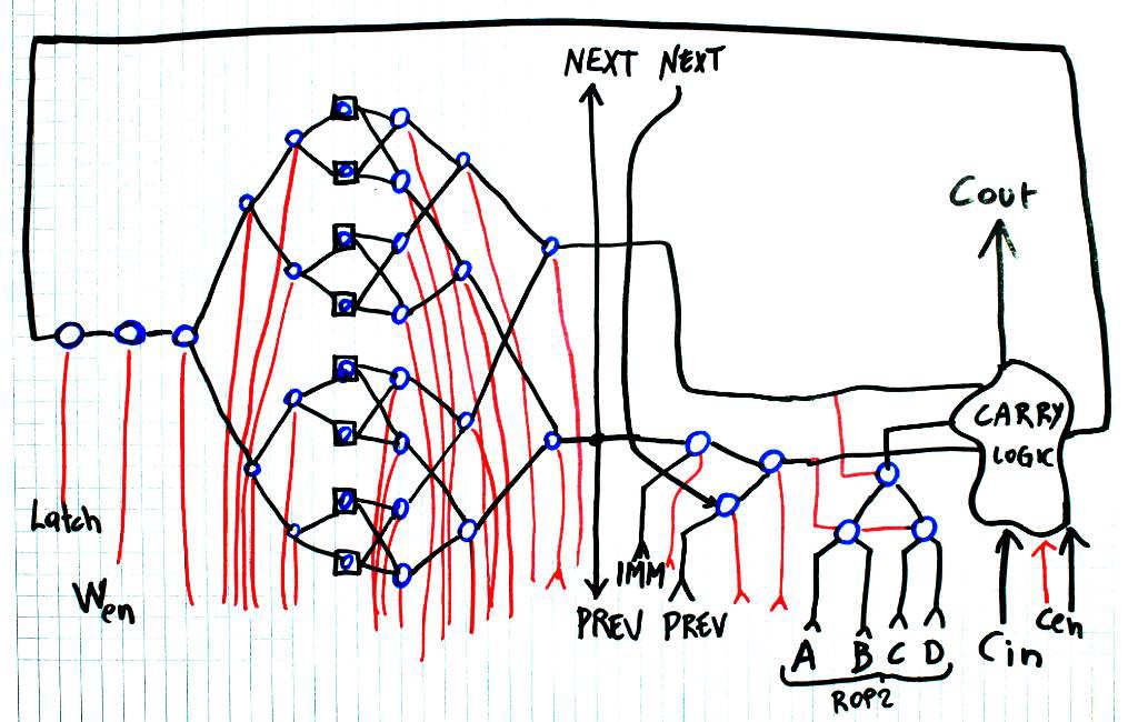
The latest diagram of a bitslice is shown here:
Blue circles are SPDT relays, red lines are control, black is data.
There are some notable tweaks since the original design :https://hackaday.io/project/14628/gallery#1974aa13d487c3bb02791679e8e65966
For example, no memory input anymore, since it's directly connected to the registers. Logic operations are now using the ROP2 system and the shift is performed before the bit operation (interesting shift & compute combinations could emerge).
The carry logic is still not defined but there is a lot of inspiration to draw from Dieter Müller. Funny how I somehow reinvented his findings before I even read his work.
Overall, the majority of the design is composed of MUX. MUX8, MUX4 and some more in the adder logic. That's important because the PBRL cells are seldom used, maybe at the ROP2 level. The rest is a lot of control signals that drive the relays with more swing and less power.
Update: I forgot to include the "zero" flag "open collector" output... A huge wired-or is essential for the control circuits!
Here's an updated version:
 Yann Guidon / YGDES

Discussions
Become a Hackaday.io Member
Create an account to leave a comment. Already have an account? Log In.
Looking a bit like a neural-net... and with your pre-biasing experiments, maybe even more-so.
Are you sure? yes | no
That was... unexpected :-D
I was more thinking of the diagrams found in the reference architecture book of the CDC6600, where they draw logic gates with squares and circles...
PDF: http://ygdes.com/CDC/DesignOfAComputer_CDC6600.pdf
(there is no excuse to not want to try to reproduce these circuit)
Are you sure? yes | no
Wow, that looks like quite a read!
Are you sure? yes | no
an excellent one. I couldn't read more than the first few chapters because the culture, vocabulary, conventions are more and more uncanny but this is a work of genius.
Not the kind of book to get asleep to, though :-P
Are you sure? yes | no